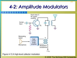
Downloaded 115 times

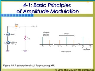
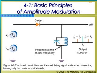
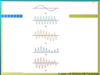
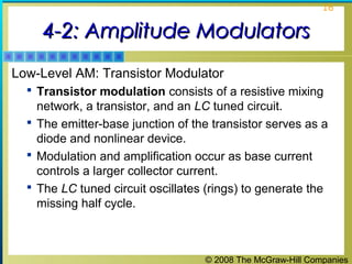
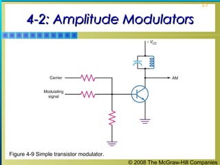
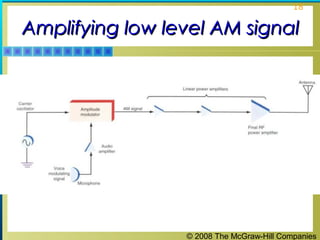
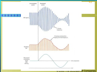
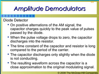
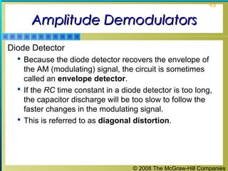
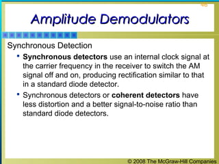
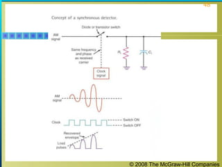
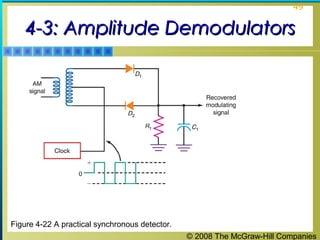

This document discusses amplitude modulation and demodulation circuits. It covers the basic principles of amplitude modulation and describes different types of amplitude modulators including diode, transistor and high-level modulators. It also discusses balanced modulators, single sideband circuits and various amplitude demodulation techniques like diode detectors and synchronous detection. Key amplitude modulation and demodulation circuits are illustrated with diagrams.