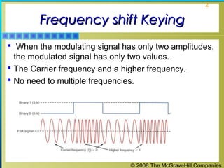
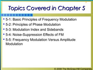
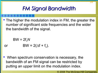
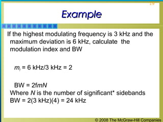
© 2008 The McGraw-Hill Companies
1
Frequency ModulationFrequency Modulation
Phase ModulationPhase Modulation
Fundamentals of Angle Modulation
© 2008 The McGraw-Hill Companies
2
Frequency shift KeyingFrequency shift Keying
 When the modulating signal has only two amplitudes,
the modulated signal has only two values.
 The Carrier frequency and a higher frequency.
 No need to multiple frequencies.
© 2008 The McGraw-Hill Companies
3
Topics Covered in Chapter 5Topics Covered in Chapter 5
 5-1: Basic Principles of Frequency Modulation
 5-2: Principles of Phase Modulation
 5-3: Modulation Index and Sidebands
 5-4: Noise-Suppression Effects of FM
 5-5: Frequency Modulation Versus Amplitude
Modulation
© 2008 The McGraw-Hill Companies
4
5-1: Basic Principles5-1: Basic Principles
of Frequency Modulationof Frequency Modulation
 A sine wave carrier can be modified for the purpose of
transmitting information from one place to another by
varying its frequency. This is known as frequency
modulation (FM).
 In FM, the carrier amplitude remains constant and the
carrier frequency is changed by the modulating signal.
© 2008 The McGraw-Hill Companies
5
5-1: Basic Principles5-1: Basic Principles
of Frequency Modulationof Frequency Modulation
 As the amplitude of the information signal varies, the
carrier frequency shifts proportionately.
 As the modulating signal amplitude increases, the
carrier frequency increases.
 With no modulation the carrier is at its normal center
or resting frequency.
© 2008 The McGraw-Hill Companies
6
5-1: Basic Principles5-1: Basic Principles
of Frequency Modulationof Frequency Modulation
Figure 5-1: FM and PM
signals. The carrier is drawn
as a triangular wave for
simplicity, but in practice it is
a sine wave. (a) Carrier. (b)
Modulating signal. (c) FM
signal. (d) PM signal.
© 2008 The McGraw-Hill Companies
7
5-1: Basic Principles5-1: Basic Principles
of Frequency Modulationof Frequency Modulation
 Frequency deviation (fd) is the amount of change in
carrier frequency produced by the modulating signal.
 The frequency deviation rate is how many times per
second the carrier frequency deviates above or below
its center frequency.
 The frequency of the modulating signal determines the
frequency deviation rate.
 A type of modulation called frequency-shift keying
(FSK) is used in transmission of binary data in digital
cell phones and low-speed computer modems.
© 2008 The McGraw-Hill Companies
8
Frequency DeviationFrequency Deviation
 The level of deviation determines the bandwidth of the
overall signal.
 The deviation used for FM is different between
different applications.
 Broadcast stations in the VHF portion of the frequency
spectrum between 88.5 and 108 MHz use large
values of deviation, typically ±75 kHz. This is known
as wideband FM (WBFM).
 These signals are capable of supporting high quality
transmissions, but occupy a large amount of
bandwidth. Usually 200 kHz is allowed for each
wideband FM transmission(BW = 2(∆f + fs).)
© 2008 The McGraw-Hill Companies
9
Frequency DeviationFrequency Deviation
 For radio communications purposes less bandwidth is
used. Narrowband FM (NBFM) often uses deviations
of around ±3 kHz or possibly slightly more. Narrower
bandwidth has advantages in terms of radio spectrum
efficiency.
© 2008 The McGraw-Hill Companies
10
Frequency DeviationFrequency Deviation
 By now it should be clear to you that …….
 Frequency of the modulating wave has no effect on
the amount of deviation, rather it defines the rate of
deviation.
© 2008 The McGraw-Hill Companies
11
ExampleExample
© 2008 The McGraw-Hill Companies
12
Modulation IndexModulation Index
 The ratio of the frequency deviation to the modulating
frequency is known as the modulation index (mf)
μ or mf = fd / fm
fd denoted as ∆f
 In most communication systems using FM, maximum
limits are put on both the frequency deviation and the
modulating frequency.
 In standard FM broadcasting, the maximum permitted
frequency deviation is 75 kHz and the maximum
permitted modulating frequency is 15 kHz.
 The modulation index for standard FM broadcasting is
therefore 5.
© 2008 The McGraw-Hill Companies
13
Side FrequenciesSide Frequencies
 Any modulation process produces side frequencies.
 In FM, when a carrier with frequency fc modulates a
signal with frequency fm, theoretically an infinite
number of side frequencies on both sides of fc are
generated.
 The distance between each of the side frequencies is
equal to the frequency of the modulating frequency.
© 2008 The McGraw-Hill Companies
14
Side FrequenciesSide Frequencies
 The amplitude of each side frequency does not follow
any simple pattern and is dependent upon the
modulation index (μ) or deviation ratio.
 At a certain distance from the carrier (fc) the power in
the side frequencies will decrease to a level where
they can be considered insignificant.
 A side frequency is considered insignificant if its
voltage amplitude is less than 10% of the un-
modulated carrier amplitude.
© 2008 The McGraw-Hill Companies
15
Side FrequenciesSide Frequencies
 The number of significant side frequencies is directly
proportional to the modulation index and can be found
from Significant side frequencies = 2 (μ+ 1)
where μ= modulation index.
A table presents the relation of different side
frequencies amplitudes
© 2008 The McGraw-Hill Companies
16
© 2008 The McGraw-Hill Companies
17
© 2008 The McGraw-Hill Companies
18
FM Signal BandwidthFM Signal Bandwidth
 The higher the modulation index in FM, the greater the
number of significant side frequencies and the wider
the bandwidth of the signal.
BW = 2fmN
or BW = 2(∆f + fm).
 When spectrum conservation is necessary, the
bandwidth of an FM signal can be restricted by
putting an upper limit on the modulation index.
© 2008 The McGraw-Hill Companies
19
ExampleExample
If the highest modulating frequency is 3 kHz and the
maximum deviation is 6 kHz, calculate the
modulation index and BW
mf = 6 kHz/3 kHz = 2
BW = 2fmN
Where N is the number of significant* sidebands
BW = 2(3 kHz)(4) = 24 kHz
© 2008 The McGraw-Hill Companies
20
FM BWFM BW
 FM radio has a significantly larger bandwidth than AM
radio.
 In FM, both the modulation index and the modulating
frequency affect the bandwidth. As the information is
made stronger, the bandwidth also grows
© 2008 The McGraw-Hill Companies
21
SNRSNR
 An FM system provides a better signal-to-noise ratio
than an AM system.
 During its transmission (propagation), a frequency
modulated wave will be subject to noise and
interference voltages. The effect of these unwanted
voltages is to vary the amplitude of the modulated
signal.
© 2008 The McGraw-Hill Companies
22
SNRSNR
 The noise amplitude variations have no effect on the
performance of the system. Information is not carried
in the amplitude of an FM wave.
 Amplitude variations are removed in the FM receiver
stage called the limiter.
 Signal-to-noise ratio of FM is primarily dependent
upon the system deviation ratio (D). .
Signal-to-noise ratio = 20 log (D sqrt 3) dB
© 2008 The McGraw-Hill Companies
23
EfficiencyEfficiency
 The efficiency of a signal is the power in the side-
bands as a fraction of the total.
 In FM signals, because of the considerable side-
bands produced, the efficiency is generally high.
 Recall that conventional AM is limited to about 33 %
efficiency when the modulation index was greater than
1.
 FM has no analogous problem.
© 2008 The McGraw-Hill Companies
24
EfficiencyEfficiency
 Efficiency is generally improved by making the
modulation index larger. i.e the bandwidth larger.
 A compromise between efficiency and SNR.
 The modulation index is normally limited to a value
between 1 and 5, depending on the application
© 2008 The McGraw-Hill Companies
25
Frequency shift KeyingFrequency shift Keying
 When the modulating signal has only two amplitudes,
the modulated signal has only two values.
 The Carrier frequency and a higher frequency.
 No need to multiple frequencies.
© 2008 The McGraw-Hill Companies
26
5-2: Principles of Phase Modulation5-2: Principles of Phase Modulation
Figure 5-6: Phase modulation of a carrier by binary data produces PSK.
© 2008 The McGraw-Hill Companies
27
5-2: Principles of Phase Modulation5-2: Principles of Phase Modulation
 When the amount of phase shift of a constant-
frequency carrier is varied in accordance with a
modulating signal, the resulting output is a phase-
modulation (PM) signal.
 Phase modulators produce a phase shift which is a
time separation between two sine waves of the same
frequency.
 The greater the amplitude of the modulating signal,
the greater the phase shift.
© 2008 The McGraw-Hill Companies
28
Principles of Phase ModulationPrinciples of Phase Modulation
As the modulating signal goes positive, the amount
of phase lag, and thus the delay of the carrier output,
increases with the amplitude of the modulating
signal. The result at the output is the same as if the
constant-frequency carrier signal had been stretched
out, or had its frequency lowered.
© 2008 The McGraw-Hill Companies
29
Principles of Phase ModulationPrinciples of Phase Modulation
 When the modulating signal goes negative, the phase shift
becomes leading. This causes the carrier sine wave to be
effectively speeded up or compressed. The result is the
same as if the carrier frequency had been increased.
© 2008 The McGraw-Hill Companies
30
 In PM. the amount of carrier deviation is proportional
to the rate of change of the modulating signal, i.e. the
calculus derivative. With a sine wave modulating
signal. The PM carrier appears to be frequency-
modulated by the cosine of the modulating signal.
© 2008 The McGraw-Hill Companies
31
5-2: Principles of Phase Modulation5-2: Principles of Phase Modulation
 The maximum frequency deviation produced by a
phase modulator occurs during the time that the
modulating signal is changing at its most rapid rate.
© 2008 The McGraw-Hill Companies
32
5-2: Principles of Phase Modulation5-2: Principles of Phase Modulation
Figure 5-3: A frequency shift
occurs in PM only when the
modulating signal amplitude
varies. (a) Modulating
signal. (b) FM signal. (c) PM
signal.
© 2008 The McGraw-Hill Companies
33
5-2: Principles of Phase Modulation5-2: Principles of Phase Modulation
Relationship between the Modulating Signal and Carrier
Deviation
 In FM and in PM, the frequency deviation is directly
proportional to the amplitude of the modulating signal.
 In PM, the maximum amount of leading or lagging
phase shift occurs at the peak amplitudes of the
modulating signal.
 In PM the carrier deviation is proportional to both the
modulating frequency and the amplitude.
© 2008 The McGraw-Hill Companies
34
5-2: Principles of Phase Modulation5-2: Principles of Phase Modulation
Figure 5-4: Frequency deviation as a function of (a) modulating signal amplitude and
(b) modulating signal frequency.
© 2008 The McGraw-Hill Companies
35
 The higher the modulating signal frequency. the
shorter is its period and the faster the voltage
changes.
 Higher modulating voltages results in greater phase
shift and this in turn produces greater frequency
deviation.
 However higher modulating frequencies produce a
faster rate of change of the modulating voltage and
thus greater frequency deviation.
© 2008 The McGraw-Hill Companies
36
 In PM then the carrier frequency deviation is
proportional to both the modulating frequency (slope
of modulating voltage) and the amplitude. In FM,
frequency deviation is proportional only to the
amplitude of the modulating signal regardless of its
frequency.
© 2008 The McGraw-Hill Companies
37
5-2: Principles of Phase Modulation5-2: Principles of Phase Modulation
Converting PM into FM
 In order to make PM compatible with FM, the deviation
produced by frequency variations in the modulating
signal must be compensated for.
 This compensation can be accomplished by passing the
intelligence signal through a low-pass RC network.
 This RC low-pass filter is called a frequency-
correcting network, predistorter, or 1/f filter and
causes the higher modulating frequencies to be
attenuated.
 The FM produced by a phase modulator is called
indirect FM.
© 2008 The McGraw-Hill Companies
38
5-2: Principles of Phase Modulation5-2: Principles of Phase Modulation
Phase-Shift Keying
 The process of phase modulating a carrier with binary
data is called phase-shift keying (PSK) or binary
phase-shift keying (BPSK).
 The PSK signal has a constant frequency, but the
phase of the signal from some reference changes as
the binary modulating signal occurs.
© 2008 The McGraw-Hill Companies
39
5-2: Principles of Phase Modulation5-2: Principles of Phase Modulation
Figure 5-6: Phase modulation of a carrier by binary data produces PSK.
© 2008 The McGraw-Hill Companies
40
5-3: Modulation Index5-3: Modulation Index
and Sidebandsand Sidebands
 Any modulation process produces sidebands.
 When a constant-frequency sine wave modulates a
carrier, side frequencies on both sides are produced.
 Side frequencies are the sum and difference of the
carrier and modulating frequency.
 The bandwidth of an FM signal is usually much wider
than that of an AM signal with the same modulating
signal.
© 2008 The McGraw-Hill Companies
41
© 2008 The McGraw-Hill Companies
42
 For the above figure, Note that the sidebands are
spaced from the carrier fc and from one another by a
frequency equal to the modulating frequency fm.
 If the modulating frequency is 1 kHz, the first pair of
sidebands is above and below the carrier by 1000 Hz.
The second pair of sidebands is above and below the
carrier by 2x 1000= 2000 Hz and so on.
 Amplitudes of side bands vary.
 Side frequencies with amplitude less than 1 percent of
the carrier are considered insignificant.
© 2008 The McGraw-Hill Companies
43
5-3: Modulation Index5-3: Modulation Index
and Sidebandsand Sidebands
Modulation Index
 The ratio of the frequency deviation to the modulating
frequency is known as the modulation index (mf).
mf = fd / fm
 In most communication systems using FM, maximum
limits are put on both the frequency deviation and the
modulating frequency.
 In standard FM broadcasting, the maximum permitted
frequency deviation is 75 kHz and the maximum
permitted modulating frequency is 15 kHz.
 The modulation index for standard FM broadcasting is
therefore 5.
© 2008 The McGraw-Hill Companies
44
5-3: Modulation Index5-3: Modulation Index
and Sidebandsand Sidebands
Bessel Functions
 The equation that expresses the phase angle in terms
of the sine wave modulating signal is solved with a
complex mathematical process known as Bessel
functions.
 Bessel coefficients are widely available and it is not
necessary to memorize or calculate them.
© 2008 The McGraw-Hill Companies
45
5-3: Modulation Index5-3: Modulation Index
and Sidebandsand Sidebands
Figure 5-8: Carrier and sideband amplitudes for different modulation indexes of FM
signals based on the Bessel functions.
© 2008 The McGraw-Hill Companies
46
5-3: Modulation Index5-3: Modulation Index
and Sidebandsand Sidebands
Figure 5-9: Plot of the Bessel function data from Fig. 5-8.
© 2008 The McGraw-Hill Companies
47
5-3: Modulation Index5-3: Modulation Index
and Sidebandsand Sidebands
Bessel Functions
 The symbol ! means factorial. This tells you to multiply
all integers from 1 through the number to which the
symbol is attached. (e.g. 5! Means 1 × 2 × 3 × 4 × 5 =
120)
 Narrowband FM (NBFM) is any FM system in which
the modulation index is less than π/2 = 1.57, or
mf < π /2.
 NBFM is widely used in communication. It conserves
spectrum space at the expense of the signal-to-noise
ratio.
© 2008 The McGraw-Hill Companies
48
5-3: Modulation Index5-3: Modulation Index
and Sidebandsand Sidebands
FM Signal Bandwidth
 The higher the modulation index in FM, the greater the
number of significant sidebands and the wider the
bandwidth of the signal.
 When spectrum conservation is necessary, the
bandwidth of an FM signal can be restricted by putting
an upper limit on the modulation index.
© 2008 The McGraw-Hill Companies
49
5-3: Modulation Index5-3: Modulation Index
and Sidebandsand Sidebands
FM Signal Bandwidth
 Example:
If the highest modulating frequency is 3 kHz and the
maximum deviation is 6 kHz, what is the modulation
index?
mf = 6 kHz/3 kHz = 2
What is the bandwidth?
BW = 2fmN
Where N is the number of significant*
sidebands
BW = 2(3 kHz)(4) = 24 kHz
*
Significant sidebands are those that have an amplitude of greater than 1% (.01)
in the Bessel table.
© 2008 The McGraw-Hill Companies
50
5-4: Noise-Suppression Effects of FM5-4: Noise-Suppression Effects of FM
 Noise is interference generated by lightning, motors,
automotive ignition systems, and power line switching
that produces transient signals.
 Noise is typically narrow spikes of voltage with high
frequencies.
 Noise (voltage spikes) add to a signal and interfere
with it.
 Some noise completely obliterates signal information.
© 2008 The McGraw-Hill Companies
51
5-4: Noise-Suppression Effects of FM5-4: Noise-Suppression Effects of FM
 FM signals have a constant modulated carrier
amplitude.
 FM receivers contain limiter circuits that deliberately
restrict the amplitude of the received signal.
 Any amplitude variations occurring on the FM signal
are effectively clipped by limiter circuits.
 This amplitude clipping does not affect the information
content of the FM signal, since it is contained solely
within the frequency variations of the carrier.
© 2008 The McGraw-Hill Companies
52
5-4: Noise-Suppression Effects of FM5-4: Noise-Suppression Effects of FM
Figure 5-11: An FM signal with noise.
© 2008 The McGraw-Hill Companies
53
5-4: Noise-Suppression Effects of FM5-4: Noise-Suppression Effects of FM
Preemphasis
 Noise can interfere with an FM signal and particularly
with the high-frequency components of the modulating
signal.
 Noise is primarily sharp spikes of energy and contains a
lot of harmonics and other high-frequency components.
 To overcome high-frequency noise, a technique known
as preemphasis is used.
 A simple high-pass filter can serve as a transmitter’s
pre-emphasis circuit.
 Pre-emphasis provides more amplification of only high-
frequency components.
© 2008 The McGraw-Hill Companies
54
5-4: Noise-Suppression Effects of FM5-4: Noise-Suppression Effects of FM
Figure 5-13 Preemphasis and deemphasis. (a) Preemphasis circuit.
© 2008 The McGraw-Hill Companies
55
5-4: Noise-Suppression Effects of FM5-4: Noise-Suppression Effects of FM
Preemphasis
 A simple low-pass filter can operate as a deemphasis
circuit in a receiver.
 A deemphasis circuit returns the frequency response to
its normal flat level.
 The combined effect of preemphasis and deemphasis is
to increase the signal-to-noise ratio for the high-
frequency components during transmission so that they
will be stronger and not masked by noise.
© 2008 The McGraw-Hill Companies
56
5-4: Noise-Suppression Effects of FM5-4: Noise-Suppression Effects of FM
Figure 5-13 Preemphasis and deemphasis. (c) Deemphasis circuit.
© 2008 The McGraw-Hill Companies
57
5-5: Frequency Modulation Versus5-5: Frequency Modulation Versus
Amplitude ModulationAmplitude Modulation
Advantages of FM
 FM typically offers some significant benefits over AM.
 FM has superior immunity to noise, made possible by
clipper limiter circuits in the receiver.
 In FM, interfering signals on the same frequency are
rejected. This is known as the capture effect.
 FM signals have a constant amplitude and there is
no need to use linear amplifiers to increase power
levels. This increases transmitter efficiency.
© 2008 The McGraw-Hill Companies
58
5-5: Frequency Modulation Versus5-5: Frequency Modulation Versus
Amplitude ModulationAmplitude Modulation
Disadvantages of FM
 FM uses considerably more frequency spectrum space.
 FM has used more complex circuitry for modulation and
demodulation.
 In the past, the circuits used for frequency modulation
and demodulation involved were complex. With the
proliferation of ICs, complex circuitry used in FM has all
but disappeared. ICs are inexpensive and easy to use.
FM and PM have become the most widely used
modulation method in electronic communication today.
© 2008 The McGraw-Hill Companies
59
5-5: Frequency Modulation Versus5-5: Frequency Modulation Versus
Amplitude ModulationAmplitude Modulation
Major applications of AM and FM

Chapter03 fm modulation

  • 1.
    © 2008 TheMcGraw-Hill Companies 1 Frequency ModulationFrequency Modulation Phase ModulationPhase Modulation Fundamentals of Angle Modulation
  • 2.
    © 2008 TheMcGraw-Hill Companies 2 Frequency shift KeyingFrequency shift Keying  When the modulating signal has only two amplitudes, the modulated signal has only two values.  The Carrier frequency and a higher frequency.  No need to multiple frequencies.
  • 3.
    © 2008 TheMcGraw-Hill Companies 3 Topics Covered in Chapter 5Topics Covered in Chapter 5  5-1: Basic Principles of Frequency Modulation  5-2: Principles of Phase Modulation  5-3: Modulation Index and Sidebands  5-4: Noise-Suppression Effects of FM  5-5: Frequency Modulation Versus Amplitude Modulation
  • 4.
    © 2008 TheMcGraw-Hill Companies 4 5-1: Basic Principles5-1: Basic Principles of Frequency Modulationof Frequency Modulation  A sine wave carrier can be modified for the purpose of transmitting information from one place to another by varying its frequency. This is known as frequency modulation (FM).  In FM, the carrier amplitude remains constant and the carrier frequency is changed by the modulating signal.
  • 5.
    © 2008 TheMcGraw-Hill Companies 5 5-1: Basic Principles5-1: Basic Principles of Frequency Modulationof Frequency Modulation  As the amplitude of the information signal varies, the carrier frequency shifts proportionately.  As the modulating signal amplitude increases, the carrier frequency increases.  With no modulation the carrier is at its normal center or resting frequency.
  • 6.
    © 2008 TheMcGraw-Hill Companies 6 5-1: Basic Principles5-1: Basic Principles of Frequency Modulationof Frequency Modulation Figure 5-1: FM and PM signals. The carrier is drawn as a triangular wave for simplicity, but in practice it is a sine wave. (a) Carrier. (b) Modulating signal. (c) FM signal. (d) PM signal.
  • 7.
    © 2008 TheMcGraw-Hill Companies 7 5-1: Basic Principles5-1: Basic Principles of Frequency Modulationof Frequency Modulation  Frequency deviation (fd) is the amount of change in carrier frequency produced by the modulating signal.  The frequency deviation rate is how many times per second the carrier frequency deviates above or below its center frequency.  The frequency of the modulating signal determines the frequency deviation rate.  A type of modulation called frequency-shift keying (FSK) is used in transmission of binary data in digital cell phones and low-speed computer modems.
  • 8.
    © 2008 TheMcGraw-Hill Companies 8 Frequency DeviationFrequency Deviation  The level of deviation determines the bandwidth of the overall signal.  The deviation used for FM is different between different applications.  Broadcast stations in the VHF portion of the frequency spectrum between 88.5 and 108 MHz use large values of deviation, typically ±75 kHz. This is known as wideband FM (WBFM).  These signals are capable of supporting high quality transmissions, but occupy a large amount of bandwidth. Usually 200 kHz is allowed for each wideband FM transmission(BW = 2(∆f + fs).)
  • 9.
    © 2008 TheMcGraw-Hill Companies 9 Frequency DeviationFrequency Deviation  For radio communications purposes less bandwidth is used. Narrowband FM (NBFM) often uses deviations of around ±3 kHz or possibly slightly more. Narrower bandwidth has advantages in terms of radio spectrum efficiency.
  • 10.
    © 2008 TheMcGraw-Hill Companies 10 Frequency DeviationFrequency Deviation  By now it should be clear to you that …….  Frequency of the modulating wave has no effect on the amount of deviation, rather it defines the rate of deviation.
  • 11.
    © 2008 TheMcGraw-Hill Companies 11 ExampleExample
  • 12.
    © 2008 TheMcGraw-Hill Companies 12 Modulation IndexModulation Index  The ratio of the frequency deviation to the modulating frequency is known as the modulation index (mf) μ or mf = fd / fm fd denoted as ∆f  In most communication systems using FM, maximum limits are put on both the frequency deviation and the modulating frequency.  In standard FM broadcasting, the maximum permitted frequency deviation is 75 kHz and the maximum permitted modulating frequency is 15 kHz.  The modulation index for standard FM broadcasting is therefore 5.
  • 13.
    © 2008 TheMcGraw-Hill Companies 13 Side FrequenciesSide Frequencies  Any modulation process produces side frequencies.  In FM, when a carrier with frequency fc modulates a signal with frequency fm, theoretically an infinite number of side frequencies on both sides of fc are generated.  The distance between each of the side frequencies is equal to the frequency of the modulating frequency.
  • 14.
    © 2008 TheMcGraw-Hill Companies 14 Side FrequenciesSide Frequencies  The amplitude of each side frequency does not follow any simple pattern and is dependent upon the modulation index (μ) or deviation ratio.  At a certain distance from the carrier (fc) the power in the side frequencies will decrease to a level where they can be considered insignificant.  A side frequency is considered insignificant if its voltage amplitude is less than 10% of the un- modulated carrier amplitude.
  • 15.
    © 2008 TheMcGraw-Hill Companies 15 Side FrequenciesSide Frequencies  The number of significant side frequencies is directly proportional to the modulation index and can be found from Significant side frequencies = 2 (μ+ 1) where μ= modulation index. A table presents the relation of different side frequencies amplitudes
  • 16.
    © 2008 TheMcGraw-Hill Companies 16
  • 17.
    © 2008 TheMcGraw-Hill Companies 17
  • 18.
    © 2008 TheMcGraw-Hill Companies 18 FM Signal BandwidthFM Signal Bandwidth  The higher the modulation index in FM, the greater the number of significant side frequencies and the wider the bandwidth of the signal. BW = 2fmN or BW = 2(∆f + fm).  When spectrum conservation is necessary, the bandwidth of an FM signal can be restricted by putting an upper limit on the modulation index.
  • 19.
    © 2008 TheMcGraw-Hill Companies 19 ExampleExample If the highest modulating frequency is 3 kHz and the maximum deviation is 6 kHz, calculate the modulation index and BW mf = 6 kHz/3 kHz = 2 BW = 2fmN Where N is the number of significant* sidebands BW = 2(3 kHz)(4) = 24 kHz
  • 20.
    © 2008 TheMcGraw-Hill Companies 20 FM BWFM BW  FM radio has a significantly larger bandwidth than AM radio.  In FM, both the modulation index and the modulating frequency affect the bandwidth. As the information is made stronger, the bandwidth also grows
  • 21.
    © 2008 TheMcGraw-Hill Companies 21 SNRSNR  An FM system provides a better signal-to-noise ratio than an AM system.  During its transmission (propagation), a frequency modulated wave will be subject to noise and interference voltages. The effect of these unwanted voltages is to vary the amplitude of the modulated signal.
  • 22.
    © 2008 TheMcGraw-Hill Companies 22 SNRSNR  The noise amplitude variations have no effect on the performance of the system. Information is not carried in the amplitude of an FM wave.  Amplitude variations are removed in the FM receiver stage called the limiter.  Signal-to-noise ratio of FM is primarily dependent upon the system deviation ratio (D). . Signal-to-noise ratio = 20 log (D sqrt 3) dB
  • 23.
    © 2008 TheMcGraw-Hill Companies 23 EfficiencyEfficiency  The efficiency of a signal is the power in the side- bands as a fraction of the total.  In FM signals, because of the considerable side- bands produced, the efficiency is generally high.  Recall that conventional AM is limited to about 33 % efficiency when the modulation index was greater than 1.  FM has no analogous problem.
  • 24.
    © 2008 TheMcGraw-Hill Companies 24 EfficiencyEfficiency  Efficiency is generally improved by making the modulation index larger. i.e the bandwidth larger.  A compromise between efficiency and SNR.  The modulation index is normally limited to a value between 1 and 5, depending on the application
  • 25.
    © 2008 TheMcGraw-Hill Companies 25 Frequency shift KeyingFrequency shift Keying  When the modulating signal has only two amplitudes, the modulated signal has only two values.  The Carrier frequency and a higher frequency.  No need to multiple frequencies.
  • 26.
    © 2008 TheMcGraw-Hill Companies 26 5-2: Principles of Phase Modulation5-2: Principles of Phase Modulation Figure 5-6: Phase modulation of a carrier by binary data produces PSK.
  • 27.
    © 2008 TheMcGraw-Hill Companies 27 5-2: Principles of Phase Modulation5-2: Principles of Phase Modulation  When the amount of phase shift of a constant- frequency carrier is varied in accordance with a modulating signal, the resulting output is a phase- modulation (PM) signal.  Phase modulators produce a phase shift which is a time separation between two sine waves of the same frequency.  The greater the amplitude of the modulating signal, the greater the phase shift.
  • 28.
    © 2008 TheMcGraw-Hill Companies 28 Principles of Phase ModulationPrinciples of Phase Modulation As the modulating signal goes positive, the amount of phase lag, and thus the delay of the carrier output, increases with the amplitude of the modulating signal. The result at the output is the same as if the constant-frequency carrier signal had been stretched out, or had its frequency lowered.
  • 29.
    © 2008 TheMcGraw-Hill Companies 29 Principles of Phase ModulationPrinciples of Phase Modulation  When the modulating signal goes negative, the phase shift becomes leading. This causes the carrier sine wave to be effectively speeded up or compressed. The result is the same as if the carrier frequency had been increased.
  • 30.
    © 2008 TheMcGraw-Hill Companies 30  In PM. the amount of carrier deviation is proportional to the rate of change of the modulating signal, i.e. the calculus derivative. With a sine wave modulating signal. The PM carrier appears to be frequency- modulated by the cosine of the modulating signal.
  • 31.
    © 2008 TheMcGraw-Hill Companies 31 5-2: Principles of Phase Modulation5-2: Principles of Phase Modulation  The maximum frequency deviation produced by a phase modulator occurs during the time that the modulating signal is changing at its most rapid rate.
  • 32.
    © 2008 TheMcGraw-Hill Companies 32 5-2: Principles of Phase Modulation5-2: Principles of Phase Modulation Figure 5-3: A frequency shift occurs in PM only when the modulating signal amplitude varies. (a) Modulating signal. (b) FM signal. (c) PM signal.
  • 33.
    © 2008 TheMcGraw-Hill Companies 33 5-2: Principles of Phase Modulation5-2: Principles of Phase Modulation Relationship between the Modulating Signal and Carrier Deviation  In FM and in PM, the frequency deviation is directly proportional to the amplitude of the modulating signal.  In PM, the maximum amount of leading or lagging phase shift occurs at the peak amplitudes of the modulating signal.  In PM the carrier deviation is proportional to both the modulating frequency and the amplitude.
  • 34.
    © 2008 TheMcGraw-Hill Companies 34 5-2: Principles of Phase Modulation5-2: Principles of Phase Modulation Figure 5-4: Frequency deviation as a function of (a) modulating signal amplitude and (b) modulating signal frequency.
  • 35.
    © 2008 TheMcGraw-Hill Companies 35  The higher the modulating signal frequency. the shorter is its period and the faster the voltage changes.  Higher modulating voltages results in greater phase shift and this in turn produces greater frequency deviation.  However higher modulating frequencies produce a faster rate of change of the modulating voltage and thus greater frequency deviation.
  • 36.
    © 2008 TheMcGraw-Hill Companies 36  In PM then the carrier frequency deviation is proportional to both the modulating frequency (slope of modulating voltage) and the amplitude. In FM, frequency deviation is proportional only to the amplitude of the modulating signal regardless of its frequency.
  • 37.
    © 2008 TheMcGraw-Hill Companies 37 5-2: Principles of Phase Modulation5-2: Principles of Phase Modulation Converting PM into FM  In order to make PM compatible with FM, the deviation produced by frequency variations in the modulating signal must be compensated for.  This compensation can be accomplished by passing the intelligence signal through a low-pass RC network.  This RC low-pass filter is called a frequency- correcting network, predistorter, or 1/f filter and causes the higher modulating frequencies to be attenuated.  The FM produced by a phase modulator is called indirect FM.
  • 38.
    © 2008 TheMcGraw-Hill Companies 38 5-2: Principles of Phase Modulation5-2: Principles of Phase Modulation Phase-Shift Keying  The process of phase modulating a carrier with binary data is called phase-shift keying (PSK) or binary phase-shift keying (BPSK).  The PSK signal has a constant frequency, but the phase of the signal from some reference changes as the binary modulating signal occurs.
  • 39.
    © 2008 TheMcGraw-Hill Companies 39 5-2: Principles of Phase Modulation5-2: Principles of Phase Modulation Figure 5-6: Phase modulation of a carrier by binary data produces PSK.
  • 40.
    © 2008 TheMcGraw-Hill Companies 40 5-3: Modulation Index5-3: Modulation Index and Sidebandsand Sidebands  Any modulation process produces sidebands.  When a constant-frequency sine wave modulates a carrier, side frequencies on both sides are produced.  Side frequencies are the sum and difference of the carrier and modulating frequency.  The bandwidth of an FM signal is usually much wider than that of an AM signal with the same modulating signal.
  • 41.
    © 2008 TheMcGraw-Hill Companies 41
  • 42.
    © 2008 TheMcGraw-Hill Companies 42  For the above figure, Note that the sidebands are spaced from the carrier fc and from one another by a frequency equal to the modulating frequency fm.  If the modulating frequency is 1 kHz, the first pair of sidebands is above and below the carrier by 1000 Hz. The second pair of sidebands is above and below the carrier by 2x 1000= 2000 Hz and so on.  Amplitudes of side bands vary.  Side frequencies with amplitude less than 1 percent of the carrier are considered insignificant.
  • 43.
    © 2008 TheMcGraw-Hill Companies 43 5-3: Modulation Index5-3: Modulation Index and Sidebandsand Sidebands Modulation Index  The ratio of the frequency deviation to the modulating frequency is known as the modulation index (mf). mf = fd / fm  In most communication systems using FM, maximum limits are put on both the frequency deviation and the modulating frequency.  In standard FM broadcasting, the maximum permitted frequency deviation is 75 kHz and the maximum permitted modulating frequency is 15 kHz.  The modulation index for standard FM broadcasting is therefore 5.
  • 44.
    © 2008 TheMcGraw-Hill Companies 44 5-3: Modulation Index5-3: Modulation Index and Sidebandsand Sidebands Bessel Functions  The equation that expresses the phase angle in terms of the sine wave modulating signal is solved with a complex mathematical process known as Bessel functions.  Bessel coefficients are widely available and it is not necessary to memorize or calculate them.
  • 45.
    © 2008 TheMcGraw-Hill Companies 45 5-3: Modulation Index5-3: Modulation Index and Sidebandsand Sidebands Figure 5-8: Carrier and sideband amplitudes for different modulation indexes of FM signals based on the Bessel functions.
  • 46.
    © 2008 TheMcGraw-Hill Companies 46 5-3: Modulation Index5-3: Modulation Index and Sidebandsand Sidebands Figure 5-9: Plot of the Bessel function data from Fig. 5-8.
  • 47.
    © 2008 TheMcGraw-Hill Companies 47 5-3: Modulation Index5-3: Modulation Index and Sidebandsand Sidebands Bessel Functions  The symbol ! means factorial. This tells you to multiply all integers from 1 through the number to which the symbol is attached. (e.g. 5! Means 1 × 2 × 3 × 4 × 5 = 120)  Narrowband FM (NBFM) is any FM system in which the modulation index is less than π/2 = 1.57, or mf < π /2.  NBFM is widely used in communication. It conserves spectrum space at the expense of the signal-to-noise ratio.
  • 48.
    © 2008 TheMcGraw-Hill Companies 48 5-3: Modulation Index5-3: Modulation Index and Sidebandsand Sidebands FM Signal Bandwidth  The higher the modulation index in FM, the greater the number of significant sidebands and the wider the bandwidth of the signal.  When spectrum conservation is necessary, the bandwidth of an FM signal can be restricted by putting an upper limit on the modulation index.
  • 49.
    © 2008 TheMcGraw-Hill Companies 49 5-3: Modulation Index5-3: Modulation Index and Sidebandsand Sidebands FM Signal Bandwidth  Example: If the highest modulating frequency is 3 kHz and the maximum deviation is 6 kHz, what is the modulation index? mf = 6 kHz/3 kHz = 2 What is the bandwidth? BW = 2fmN Where N is the number of significant* sidebands BW = 2(3 kHz)(4) = 24 kHz * Significant sidebands are those that have an amplitude of greater than 1% (.01) in the Bessel table.
  • 50.
    © 2008 TheMcGraw-Hill Companies 50 5-4: Noise-Suppression Effects of FM5-4: Noise-Suppression Effects of FM  Noise is interference generated by lightning, motors, automotive ignition systems, and power line switching that produces transient signals.  Noise is typically narrow spikes of voltage with high frequencies.  Noise (voltage spikes) add to a signal and interfere with it.  Some noise completely obliterates signal information.
  • 51.
    © 2008 TheMcGraw-Hill Companies 51 5-4: Noise-Suppression Effects of FM5-4: Noise-Suppression Effects of FM  FM signals have a constant modulated carrier amplitude.  FM receivers contain limiter circuits that deliberately restrict the amplitude of the received signal.  Any amplitude variations occurring on the FM signal are effectively clipped by limiter circuits.  This amplitude clipping does not affect the information content of the FM signal, since it is contained solely within the frequency variations of the carrier.
  • 52.
    © 2008 TheMcGraw-Hill Companies 52 5-4: Noise-Suppression Effects of FM5-4: Noise-Suppression Effects of FM Figure 5-11: An FM signal with noise.
  • 53.
    © 2008 TheMcGraw-Hill Companies 53 5-4: Noise-Suppression Effects of FM5-4: Noise-Suppression Effects of FM Preemphasis  Noise can interfere with an FM signal and particularly with the high-frequency components of the modulating signal.  Noise is primarily sharp spikes of energy and contains a lot of harmonics and other high-frequency components.  To overcome high-frequency noise, a technique known as preemphasis is used.  A simple high-pass filter can serve as a transmitter’s pre-emphasis circuit.  Pre-emphasis provides more amplification of only high- frequency components.
  • 54.
    © 2008 TheMcGraw-Hill Companies 54 5-4: Noise-Suppression Effects of FM5-4: Noise-Suppression Effects of FM Figure 5-13 Preemphasis and deemphasis. (a) Preemphasis circuit.
  • 55.
    © 2008 TheMcGraw-Hill Companies 55 5-4: Noise-Suppression Effects of FM5-4: Noise-Suppression Effects of FM Preemphasis  A simple low-pass filter can operate as a deemphasis circuit in a receiver.  A deemphasis circuit returns the frequency response to its normal flat level.  The combined effect of preemphasis and deemphasis is to increase the signal-to-noise ratio for the high- frequency components during transmission so that they will be stronger and not masked by noise.
  • 56.
    © 2008 TheMcGraw-Hill Companies 56 5-4: Noise-Suppression Effects of FM5-4: Noise-Suppression Effects of FM Figure 5-13 Preemphasis and deemphasis. (c) Deemphasis circuit.
  • 57.
    © 2008 TheMcGraw-Hill Companies 57 5-5: Frequency Modulation Versus5-5: Frequency Modulation Versus Amplitude ModulationAmplitude Modulation Advantages of FM  FM typically offers some significant benefits over AM.  FM has superior immunity to noise, made possible by clipper limiter circuits in the receiver.  In FM, interfering signals on the same frequency are rejected. This is known as the capture effect.  FM signals have a constant amplitude and there is no need to use linear amplifiers to increase power levels. This increases transmitter efficiency.
  • 58.
    © 2008 TheMcGraw-Hill Companies 58 5-5: Frequency Modulation Versus5-5: Frequency Modulation Versus Amplitude ModulationAmplitude Modulation Disadvantages of FM  FM uses considerably more frequency spectrum space.  FM has used more complex circuitry for modulation and demodulation.  In the past, the circuits used for frequency modulation and demodulation involved were complex. With the proliferation of ICs, complex circuitry used in FM has all but disappeared. ICs are inexpensive and easy to use. FM and PM have become the most widely used modulation method in electronic communication today.
  • 59.
    © 2008 TheMcGraw-Hill Companies 59 5-5: Frequency Modulation Versus5-5: Frequency Modulation Versus Amplitude ModulationAmplitude Modulation Major applications of AM and FM