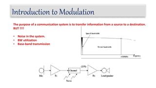
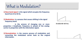
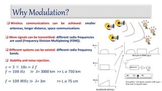
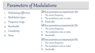
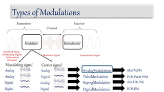
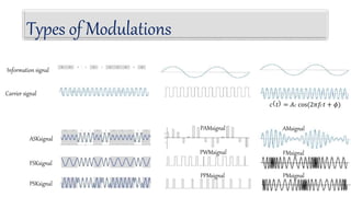
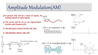
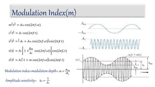
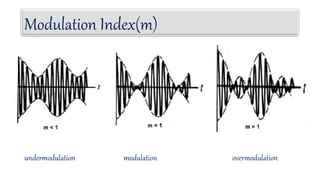
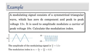
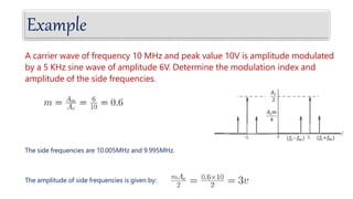
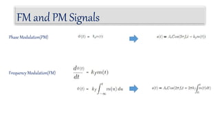
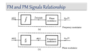
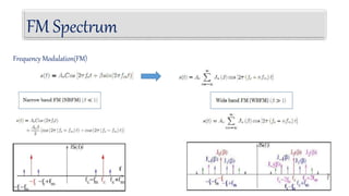
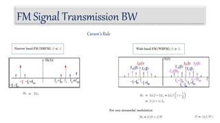
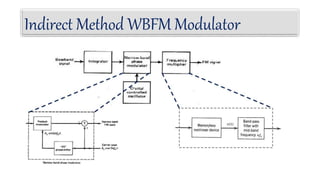
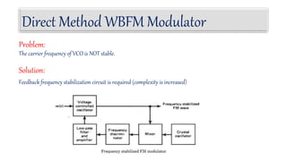
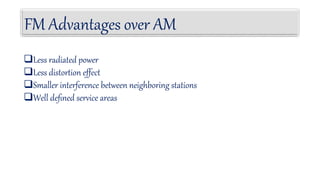
Modulation
By: Endalew Abich
Date: 15/01/2009
1. Analogue Modulation
1.1. Amplitude Modulation (AM)
1.2. Frequency Modulation (FM)
1.3. Phase Modulation(PM)
Outline
Introduction to Modulation
The purpose of a communication system is to transfer information from a source to a destination.
BUT !!!!
• Noise in the system.
• BW utilization
• Base-band transmission
 Base band signal: is the signal which occupies the frequency
band from 0 to W-Hz.
 Modulation: is a process that causes shifting in the signal
frequency band.
is the process of changing one or more
properties ( Amplitude, frequency or phase) of the analog
carrier in proportion with the information signal.
 Demodulation: is the reverse process of modulation and
converting the modulated carrier back to the original
information.
What is Modulation?
 Wireless communications can be achieved: smaller
antennas, longer distance, space communications
 More signals can be transmitted: different radio frequencies
are used (Frequency Division Multiplexing (FDM)).
 Different systems can be existed: different radio frequency
bands.
 Stability and noise rejection.
𝑐 = 3 × 108 = 𝜆 𝑓
𝑓 = 100 𝐻𝑧 ≫ 𝜆= 3000 km >> L 𝛼 750 km
𝑓 = 100 𝑀𝐻𝑧 ≫ 𝜆= 3m >> L 𝛼 75 cm
Why Modulation?
1. Modulating difference.
2. Modulation types.
3. Frequency range.
4. Bandwidth.
5. Complexity.
6. Noise.
Parameters of Modulations
Three parameters are important for FM:
I. The carrier frequency.
II. The modulation ratio or index.
III. Bandwidth.
Three parameters are important for AM:
I. The carrier frequency.
II. The modulation ratio or index.
III. Bandwidth.
Three parameters are important for PM:
I. The carrier frequency.
II. The modulation ratio or index.
III. Bandwidth.
Types of Modulations
Channel
Transmitter Receiver
Demodulator
Demodulated Signal
AnalogModulation
PulseModulation
KeyingModulation
DigitalModulation
AM,FM,PM
PAM,PWM,PPM
ASK,FSK,PSK
PCM,DM
Modulator
Baseband Signal
(Modulating Signal)
(information)
(message)
Modulating signal
Analog
Analog
Digital
Digital
Modulated Signal
Carrier signal
Analog
Digital
Analog
Digital
FMsignal
PMsignal
PAMsignal
PWMsignal
PPMsignal
ASKsignal
FSKsignal
PSKsignal
Types of Modulations
Information signal
Carrier signal
𝑐
𝑐 𝑡 = 𝐴𝑐 cos(2𝜋𝑓 𝑡 + 𝜙)
AMsignal
Amplitude Modulation(AM)
𝑀(𝑓)
𝐶(𝑓)
𝑆(𝑓)
 In general m(t) will be a band of signals, for
example speech or video signals.
 The carrier will be sin or cos trigonometric
function with frequency (fc)
 The AM signal contains the DC, LSB, USB.
 DSB-WC(AM), DSB-SC, SSB, VSB
𝑐
𝑚(𝑡)
𝑐 𝑡 = 𝐴𝑐 cos(2𝜋𝑓 𝑡 + 𝜙)
𝑐
𝑠 𝑡 = 𝐴𝑐+𝑚(𝑡) cos(2𝜋𝑓 𝑡 + 𝜙)
𝑐
𝐴𝑐+𝑚(𝑡) cos(2𝜋𝑓 𝑡 + 𝜙)
𝐴𝑐+𝑚(𝑡)
𝑐
𝑐
Modulation Index(m)
𝑚 𝑡 = 𝐴𝑚 cos(2𝜋𝑓𝑚𝑡)
𝑐 𝑡 = 𝐴𝑐 cos(2𝜋𝑓 𝑡)
s t = 𝐴𝑐 + 𝐴𝑚 cos(2𝜋𝑓𝑚𝑡) cos(2𝜋𝑓 𝑡)
s t = 𝐴𝑐 1 +
𝐴𝑚
𝐴𝑐
𝑐
cos(2𝜋𝑓𝑚𝑡) cos(2𝜋𝑓 𝑡)
𝑐
𝑐
s t = 𝐴𝑐 1 + 𝑚 cos(2𝜋𝑓𝑚𝑡) cos(2𝜋𝑓 𝑡)
Modulation index=modulation depth= 𝑚 =
Amplitude sensitivity= 𝑘𝑎 =
1
𝐴𝑐
Modulation Index(m)
overmodulation
undermodulation modulation
Example
11
10
-10
𝛿 𝑓 − 𝑓 𝑐 + 𝛿 𝑓 + 𝑓 𝑐
𝑚(𝑡)
𝑐(𝑡)
𝐴𝑐
AM Signal Equations
𝑀(𝑓)
𝐶(𝑓)
2𝜋𝐴𝑐 𝛿 𝑤 = 𝐴𝑐 𝛿 𝑓
𝑐
𝐴𝑐 cos(2𝜋𝑓 𝑡)
=
𝜋𝐴𝑐 𝛿 𝑤 − 𝑤𝑐 + 𝛿 𝑤 + 𝑤𝑐
𝐴𝑐
2
𝑐
𝑐 𝑐
𝑠 𝑡 = 𝐴𝑐+𝑚(𝑡) cos(2𝜋𝑓 𝑡)
= 𝐴𝑐cos(2𝜋𝑓 𝑡) + 𝑚(𝑡)cos(2𝜋𝑓 𝑡)
=
𝐴𝑐
2
𝛿 𝑓 − 𝑓 + 𝛿 𝑓 + 𝑓
𝑐 𝑐 +
1
2
𝑀 𝑓 − 𝑓 + 𝑀 𝑓 + 𝑓
𝑐 𝑐
AM Signal Equations
𝑐
𝑚 𝑡 = 𝐴𝑚 cos(2𝜋𝑓 𝑚𝑡)
𝑐 𝑡 = 𝐴𝑐 cos(2𝜋𝑓 𝑡)
𝐴𝑚
2
𝐴𝑐
2
𝛿 𝑓 − 𝑓𝑚 + 𝛿 𝑓 +𝑓𝑚
𝛿 𝑓 − 𝑓 + 𝛿 𝑓 + 𝑓
𝑐 𝑐
𝑐
𝑐 𝑐
s t = 𝐴𝑐 1 + 𝑚 cos(2𝜋𝑓 𝑚𝑡) cos(2𝜋𝑓 𝑡)
= 𝐴𝑐cos(2𝜋𝑓 𝑡)+ 𝐴𝑐𝑚 cos(2𝜋𝑓 𝑚𝑡) cos(2𝜋𝑓 𝑡)
𝑐
= 𝐴𝑐cos(2𝜋𝑓 𝑡)+
𝐴𝑐𝑚
2 𝑐
cos 2𝜋(𝑓 −𝑓 𝑚)𝑡 𝑐
+ cos(2𝜋(𝑓 +𝑓 𝑚)𝑡)
Power Considerations
𝑐
s(t) = 𝐴𝑐cos(2𝜋𝑓 𝑡)+
𝐴𝑐𝑚
2 𝑐
cos 2𝜋(𝑓 −𝑓 𝑚)𝑡 𝑐
+ cos(2𝜋(𝑓 +𝑓 𝑚)𝑡)
𝑎𝑡 𝑚 = 1 ≫ 𝜂 = 16.7%
Example
A carrier wave of frequency 10 MHz and peak value 10V is amplitude modulated
by a 5 KHz sine wave of amplitude 6V. Determine the modulation index and
amplitude of the side frequencies.
The side frequencies are 10.005MHz and 9.995MHz.
The amplitude of side frequencies is given by:
Example
Suppose you have a portable AM transmitter which needs to transmit an average power of 10 Watts
in each sideband when modulation depth m = 0.3. Assume that the transmitter is powered by a 12
Volt battery. Calculate the total consumed current from the battery.
10 Watt
444.44 Watt
444.44 + 10 + 10 = 464.44 Watt
Battery current = power/volt = 38.70 Ampere !!!! Large and heavy 12v battery
Other Amplitude Modulation Techniques
𝐴𝑐
2
𝛿 𝑓 − 𝑓 + 𝛿 𝑓 + 𝑓
𝑐 𝑐 +
1
2
𝑀 𝑓 − 𝑓 + 𝑀 𝑓 + 𝑓
𝑐 𝑐
DSB-WC(AM)=
=
1
2
𝑀 𝑓 − 𝑓 + 𝑀 𝑓 + 𝑓
𝑐 𝑐
DSB-SC
SSB-SC =
1
2 𝑀+ 𝑓 − 𝑓 + 𝑀+ 𝑓 +𝑓
𝑐 𝑐
Bandwidth=2W
Bandwidth=2W
Bandwidth=W
Angle Modulation
The instantaneous phase(angle)
The instantaneous frequency
The instantaneous phase deviation
The instantaneous frequency deviation
FM and PM Signals
Phase Modulation(PM)
Frequency Modulation(FM)
FM and PM Signals
AM signal
FM signal
PM signal
Information signal
Carrier signal
FM and PM Signals Relationship
Example
Single Tone Modulation
Phase Modulation(PM)
Frequency Modulation(FM)
FM Spectrum
Frequency Modulation(FM)
FM Signal Power
Frequency Modulation(FM)
Example
FM Signal Transmission BW
FMSignal
FM Signal Transmission BW
Carson’s Rule
FM Signal Transmission BW
Universal Curve
FM Signal Generation
Indirect Method Direct Method
Indirect Method WBFM Modulator
Armstrong’s Method
Armstrong’s Method Example
NBFM A B C
NBFM Output:
At the Point A:
At the Point B:
At the Point C:
f= 500K × 162 = 81 MHz
f= 81MHz - 77.97MHz= 3.03 MHz
f= 3.03MHz × 30 = 90.9 MHz
∆f= 15.432 × 162 = 2499.98 Hz
∆f= 2499.98 Hz
∆f= 15.432 × 30 = 74999.52 Hz
= 75 KHz
Direct Method WBFM Modulator
 The carrier frequency is directly varied by the input signal
 This Can be accomplished by Voltage-Controlled Oscillator(VCO), whose output frequency is proportional to
The voltage of the input signal.
 A VCO example: implemented by variable capacitor
Direct Method WBFM Modulator
The carrier frequency of VCO is NOT stable.
Problem:
Solution:
Feedback frequency stabilization circuit is required (complexity is increased)
FM Signal Demodulation
Indirect Method Direct Method
To recover the message m(t):
Need a circuit whose output is proportional to the difference
of the instantaneous frequency from the carrier frequency:
Frequency Discriminator
AMSignal
Phase Locked Loop(PLL)
 A negative feedback system
 Has many applications in communications:
 Carrier synchronization:
 Demodulation: e.g., DSB, FM
 Frequency multiplication and division
 Three main components:
 Phase detector (Multiplier)
 Loop filter: low pass filter
 Voltage controlled oscillator(VCO): a FM system
 Today’s goal:
 PLL for FM demodulation
FM Advantages over AM
Less radiated power
Less distortion effect
Smaller interference between neighboring stations
Well defined service areas
FM Disadvantages
High Bandwidth required
complicated receivers and transmitters
Comparison of AM and FM
Parameter AM FM
Origin AM method of audio transmission was first
successfully carried out in the mid 1870s.
FM radio was developed in the United states mainly
by Edwin Armstrong in the 1930s.
Modulating
differences
In AM, a radio wave known as the "carrier"
or "carrier wave" is modulated in amplitude
by the signal that is to be transmitted
In FM, a radio wave known as the "carrier" or
"carrier wave" is modulated in frequency by the
signal that is to be transmitted.
Importance
It is used in both analog and digital
communication and telemetry
It is used in both analog and digital communication
and telemetry
Frequency Range AM radio ranges from 535 to 1705 KHz (OR)
Up to 1200 Bits per second.
FM radio ranges in a higher spectrum from 88 to
108 MHz. (OR) 1200 to 2400 bits per second.
Comparison of AM and FM
Parameter AM FM
Bandwidth
Requirements
Twice the highest modulating frequency. Twice the sum of the modulating signal
frequency and the frequency deviation.
Complexity Transmitter and receiver are simple. Transmitter and receiver are more
complex.(i.e. voltage to frequency and
frequency to voltage conversion has to be
done).
Noise AM is more susceptible to noise. FM is less susceptible to noise.
Comparison of FM and PM
No. FM PM
1 The max frequency deviation
depends on amplitude of modulating
signal and its frequency
The max phase deviation depends
on amplitude of modulating signal
2 Frequency of the carrier is
modulated by modulating signal.
Phase of the carrier is modulated by
modulating signal.
3 Modulation index is increased as
modulation frequency is reduced
and vice versa.
Modulation index remains same if
modulating signal frequency is
change.

Analog Modulation for communication.pptx

  • 1.
  • 2.
    1. Analogue Modulation 1.1.Amplitude Modulation (AM) 1.2. Frequency Modulation (FM) 1.3. Phase Modulation(PM) Outline
  • 3.
    Introduction to Modulation Thepurpose of a communication system is to transfer information from a source to a destination. BUT !!!! • Noise in the system. • BW utilization • Base-band transmission
  • 4.
     Base bandsignal: is the signal which occupies the frequency band from 0 to W-Hz.  Modulation: is a process that causes shifting in the signal frequency band. is the process of changing one or more properties ( Amplitude, frequency or phase) of the analog carrier in proportion with the information signal.  Demodulation: is the reverse process of modulation and converting the modulated carrier back to the original information. What is Modulation?
  • 5.
     Wireless communicationscan be achieved: smaller antennas, longer distance, space communications  More signals can be transmitted: different radio frequencies are used (Frequency Division Multiplexing (FDM)).  Different systems can be existed: different radio frequency bands.  Stability and noise rejection. 𝑐 = 3 × 108 = 𝜆 𝑓 𝑓 = 100 𝐻𝑧 ≫ 𝜆= 3000 km >> L 𝛼 750 km 𝑓 = 100 𝑀𝐻𝑧 ≫ 𝜆= 3m >> L 𝛼 75 cm Why Modulation?
  • 6.
    1. Modulating difference. 2.Modulation types. 3. Frequency range. 4. Bandwidth. 5. Complexity. 6. Noise. Parameters of Modulations Three parameters are important for FM: I. The carrier frequency. II. The modulation ratio or index. III. Bandwidth. Three parameters are important for AM: I. The carrier frequency. II. The modulation ratio or index. III. Bandwidth. Three parameters are important for PM: I. The carrier frequency. II. The modulation ratio or index. III. Bandwidth.
  • 7.
    Types of Modulations Channel TransmitterReceiver Demodulator Demodulated Signal AnalogModulation PulseModulation KeyingModulation DigitalModulation AM,FM,PM PAM,PWM,PPM ASK,FSK,PSK PCM,DM Modulator Baseband Signal (Modulating Signal) (information) (message) Modulating signal Analog Analog Digital Digital Modulated Signal Carrier signal Analog Digital Analog Digital
  • 8.
    FMsignal PMsignal PAMsignal PWMsignal PPMsignal ASKsignal FSKsignal PSKsignal Types of Modulations Informationsignal Carrier signal 𝑐 𝑐 𝑡 = 𝐴𝑐 cos(2𝜋𝑓 𝑡 + 𝜙) AMsignal
  • 9.
    Amplitude Modulation(AM) 𝑀(𝑓) 𝐶(𝑓) 𝑆(𝑓)  Ingeneral m(t) will be a band of signals, for example speech or video signals.  The carrier will be sin or cos trigonometric function with frequency (fc)  The AM signal contains the DC, LSB, USB.  DSB-WC(AM), DSB-SC, SSB, VSB 𝑐 𝑚(𝑡) 𝑐 𝑡 = 𝐴𝑐 cos(2𝜋𝑓 𝑡 + 𝜙) 𝑐 𝑠 𝑡 = 𝐴𝑐+𝑚(𝑡) cos(2𝜋𝑓 𝑡 + 𝜙) 𝑐 𝐴𝑐+𝑚(𝑡) cos(2𝜋𝑓 𝑡 + 𝜙) 𝐴𝑐+𝑚(𝑡)
  • 10.
    𝑐 𝑐 Modulation Index(m) 𝑚 𝑡= 𝐴𝑚 cos(2𝜋𝑓𝑚𝑡) 𝑐 𝑡 = 𝐴𝑐 cos(2𝜋𝑓 𝑡) s t = 𝐴𝑐 + 𝐴𝑚 cos(2𝜋𝑓𝑚𝑡) cos(2𝜋𝑓 𝑡) s t = 𝐴𝑐 1 + 𝐴𝑚 𝐴𝑐 𝑐 cos(2𝜋𝑓𝑚𝑡) cos(2𝜋𝑓 𝑡) 𝑐 𝑐 s t = 𝐴𝑐 1 + 𝑚 cos(2𝜋𝑓𝑚𝑡) cos(2𝜋𝑓 𝑡) Modulation index=modulation depth= 𝑚 = Amplitude sensitivity= 𝑘𝑎 = 1 𝐴𝑐
  • 11.
  • 12.
  • 13.
    𝛿 𝑓 −𝑓 𝑐 + 𝛿 𝑓 + 𝑓 𝑐 𝑚(𝑡) 𝑐(𝑡) 𝐴𝑐 AM Signal Equations 𝑀(𝑓) 𝐶(𝑓) 2𝜋𝐴𝑐 𝛿 𝑤 = 𝐴𝑐 𝛿 𝑓 𝑐 𝐴𝑐 cos(2𝜋𝑓 𝑡) = 𝜋𝐴𝑐 𝛿 𝑤 − 𝑤𝑐 + 𝛿 𝑤 + 𝑤𝑐 𝐴𝑐 2 𝑐 𝑐 𝑐 𝑠 𝑡 = 𝐴𝑐+𝑚(𝑡) cos(2𝜋𝑓 𝑡) = 𝐴𝑐cos(2𝜋𝑓 𝑡) + 𝑚(𝑡)cos(2𝜋𝑓 𝑡) = 𝐴𝑐 2 𝛿 𝑓 − 𝑓 + 𝛿 𝑓 + 𝑓 𝑐 𝑐 + 1 2 𝑀 𝑓 − 𝑓 + 𝑀 𝑓 + 𝑓 𝑐 𝑐
  • 14.
    AM Signal Equations 𝑐 𝑚𝑡 = 𝐴𝑚 cos(2𝜋𝑓 𝑚𝑡) 𝑐 𝑡 = 𝐴𝑐 cos(2𝜋𝑓 𝑡) 𝐴𝑚 2 𝐴𝑐 2 𝛿 𝑓 − 𝑓𝑚 + 𝛿 𝑓 +𝑓𝑚 𝛿 𝑓 − 𝑓 + 𝛿 𝑓 + 𝑓 𝑐 𝑐 𝑐 𝑐 𝑐 s t = 𝐴𝑐 1 + 𝑚 cos(2𝜋𝑓 𝑚𝑡) cos(2𝜋𝑓 𝑡) = 𝐴𝑐cos(2𝜋𝑓 𝑡)+ 𝐴𝑐𝑚 cos(2𝜋𝑓 𝑚𝑡) cos(2𝜋𝑓 𝑡) 𝑐 = 𝐴𝑐cos(2𝜋𝑓 𝑡)+ 𝐴𝑐𝑚 2 𝑐 cos 2𝜋(𝑓 −𝑓 𝑚)𝑡 𝑐 + cos(2𝜋(𝑓 +𝑓 𝑚)𝑡)
  • 15.
    Power Considerations 𝑐 s(t) =𝐴𝑐cos(2𝜋𝑓 𝑡)+ 𝐴𝑐𝑚 2 𝑐 cos 2𝜋(𝑓 −𝑓 𝑚)𝑡 𝑐 + cos(2𝜋(𝑓 +𝑓 𝑚)𝑡) 𝑎𝑡 𝑚 = 1 ≫ 𝜂 = 16.7%
  • 16.
    Example A carrier waveof frequency 10 MHz and peak value 10V is amplitude modulated by a 5 KHz sine wave of amplitude 6V. Determine the modulation index and amplitude of the side frequencies. The side frequencies are 10.005MHz and 9.995MHz. The amplitude of side frequencies is given by:
  • 17.
    Example Suppose you havea portable AM transmitter which needs to transmit an average power of 10 Watts in each sideband when modulation depth m = 0.3. Assume that the transmitter is powered by a 12 Volt battery. Calculate the total consumed current from the battery. 10 Watt 444.44 Watt 444.44 + 10 + 10 = 464.44 Watt Battery current = power/volt = 38.70 Ampere !!!! Large and heavy 12v battery
  • 18.
    Other Amplitude ModulationTechniques 𝐴𝑐 2 𝛿 𝑓 − 𝑓 + 𝛿 𝑓 + 𝑓 𝑐 𝑐 + 1 2 𝑀 𝑓 − 𝑓 + 𝑀 𝑓 + 𝑓 𝑐 𝑐 DSB-WC(AM)= = 1 2 𝑀 𝑓 − 𝑓 + 𝑀 𝑓 + 𝑓 𝑐 𝑐 DSB-SC SSB-SC = 1 2 𝑀+ 𝑓 − 𝑓 + 𝑀+ 𝑓 +𝑓 𝑐 𝑐 Bandwidth=2W Bandwidth=2W Bandwidth=W
  • 19.
    Angle Modulation The instantaneousphase(angle) The instantaneous frequency The instantaneous phase deviation The instantaneous frequency deviation
  • 20.
    FM and PMSignals Phase Modulation(PM) Frequency Modulation(FM)
  • 21.
    FM and PMSignals AM signal FM signal PM signal Information signal Carrier signal
  • 22.
    FM and PMSignals Relationship
  • 23.
  • 24.
    Single Tone Modulation PhaseModulation(PM) Frequency Modulation(FM)
  • 25.
  • 26.
  • 27.
  • 28.
  • 29.
    FM Signal TransmissionBW Carson’s Rule
  • 30.
    FM Signal TransmissionBW Universal Curve
  • 31.
    FM Signal Generation IndirectMethod Direct Method
  • 32.
  • 33.
  • 34.
    Armstrong’s Method Example NBFMA B C NBFM Output: At the Point A: At the Point B: At the Point C: f= 500K × 162 = 81 MHz f= 81MHz - 77.97MHz= 3.03 MHz f= 3.03MHz × 30 = 90.9 MHz ∆f= 15.432 × 162 = 2499.98 Hz ∆f= 2499.98 Hz ∆f= 15.432 × 30 = 74999.52 Hz = 75 KHz
  • 35.
    Direct Method WBFMModulator  The carrier frequency is directly varied by the input signal  This Can be accomplished by Voltage-Controlled Oscillator(VCO), whose output frequency is proportional to The voltage of the input signal.  A VCO example: implemented by variable capacitor
  • 36.
    Direct Method WBFMModulator The carrier frequency of VCO is NOT stable. Problem: Solution: Feedback frequency stabilization circuit is required (complexity is increased)
  • 37.
    FM Signal Demodulation IndirectMethod Direct Method To recover the message m(t): Need a circuit whose output is proportional to the difference of the instantaneous frequency from the carrier frequency:
  • 38.
  • 39.
    Phase Locked Loop(PLL) A negative feedback system  Has many applications in communications:  Carrier synchronization:  Demodulation: e.g., DSB, FM  Frequency multiplication and division  Three main components:  Phase detector (Multiplier)  Loop filter: low pass filter  Voltage controlled oscillator(VCO): a FM system  Today’s goal:  PLL for FM demodulation
  • 40.
    FM Advantages overAM Less radiated power Less distortion effect Smaller interference between neighboring stations Well defined service areas
  • 41.
    FM Disadvantages High Bandwidthrequired complicated receivers and transmitters
  • 42.
    Comparison of AMand FM Parameter AM FM Origin AM method of audio transmission was first successfully carried out in the mid 1870s. FM radio was developed in the United states mainly by Edwin Armstrong in the 1930s. Modulating differences In AM, a radio wave known as the "carrier" or "carrier wave" is modulated in amplitude by the signal that is to be transmitted In FM, a radio wave known as the "carrier" or "carrier wave" is modulated in frequency by the signal that is to be transmitted. Importance It is used in both analog and digital communication and telemetry It is used in both analog and digital communication and telemetry Frequency Range AM radio ranges from 535 to 1705 KHz (OR) Up to 1200 Bits per second. FM radio ranges in a higher spectrum from 88 to 108 MHz. (OR) 1200 to 2400 bits per second.
  • 43.
    Comparison of AMand FM Parameter AM FM Bandwidth Requirements Twice the highest modulating frequency. Twice the sum of the modulating signal frequency and the frequency deviation. Complexity Transmitter and receiver are simple. Transmitter and receiver are more complex.(i.e. voltage to frequency and frequency to voltage conversion has to be done). Noise AM is more susceptible to noise. FM is less susceptible to noise.
  • 44.
    Comparison of FMand PM No. FM PM 1 The max frequency deviation depends on amplitude of modulating signal and its frequency The max phase deviation depends on amplitude of modulating signal 2 Frequency of the carrier is modulated by modulating signal. Phase of the carrier is modulated by modulating signal. 3 Modulation index is increased as modulation frequency is reduced and vice versa. Modulation index remains same if modulating signal frequency is change.

Editor's Notes