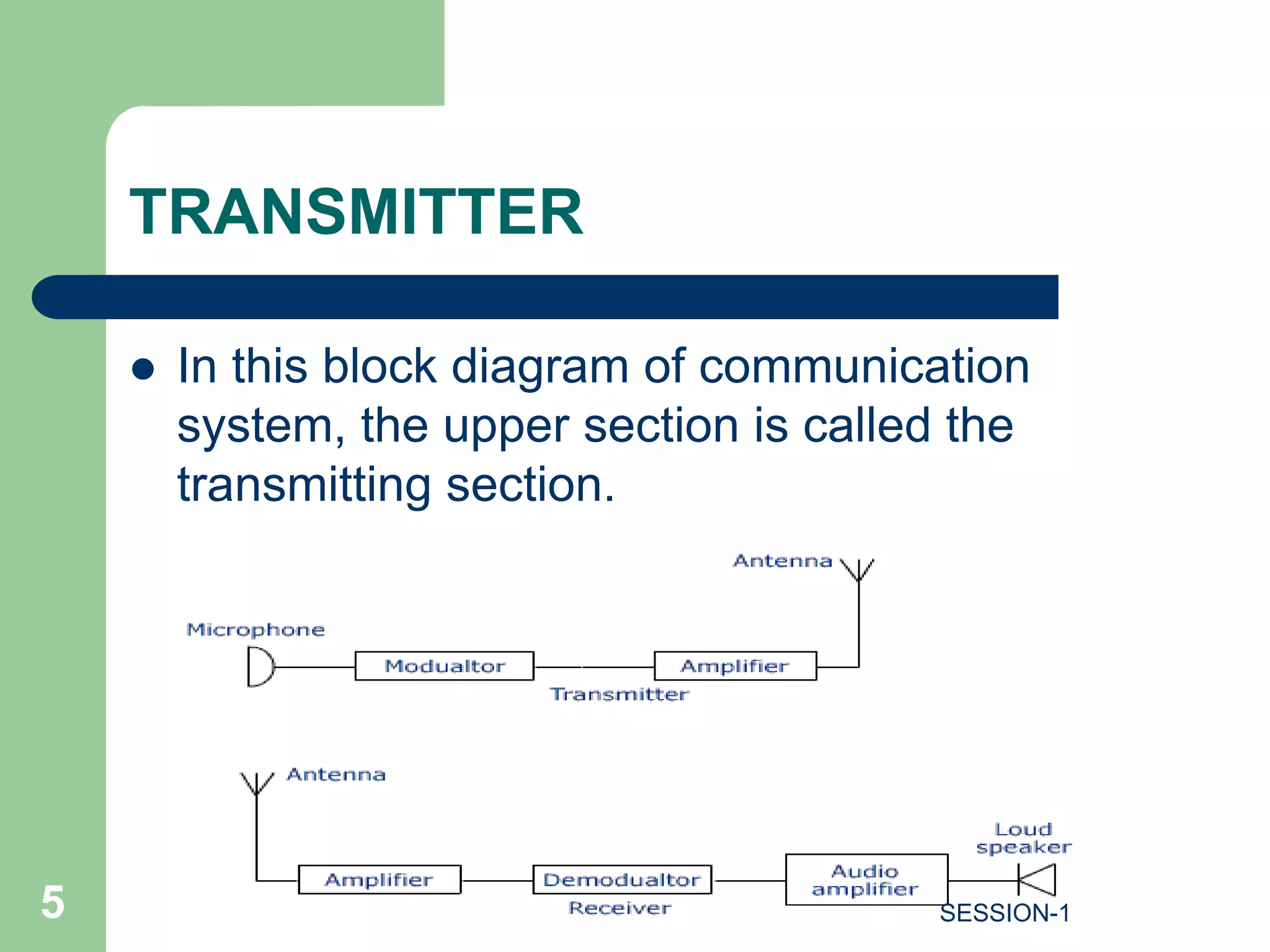
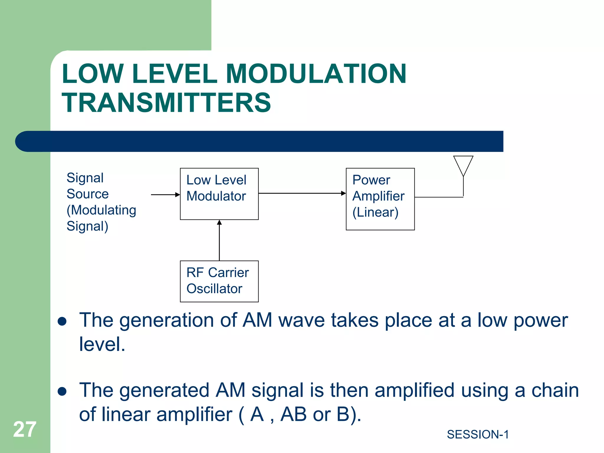
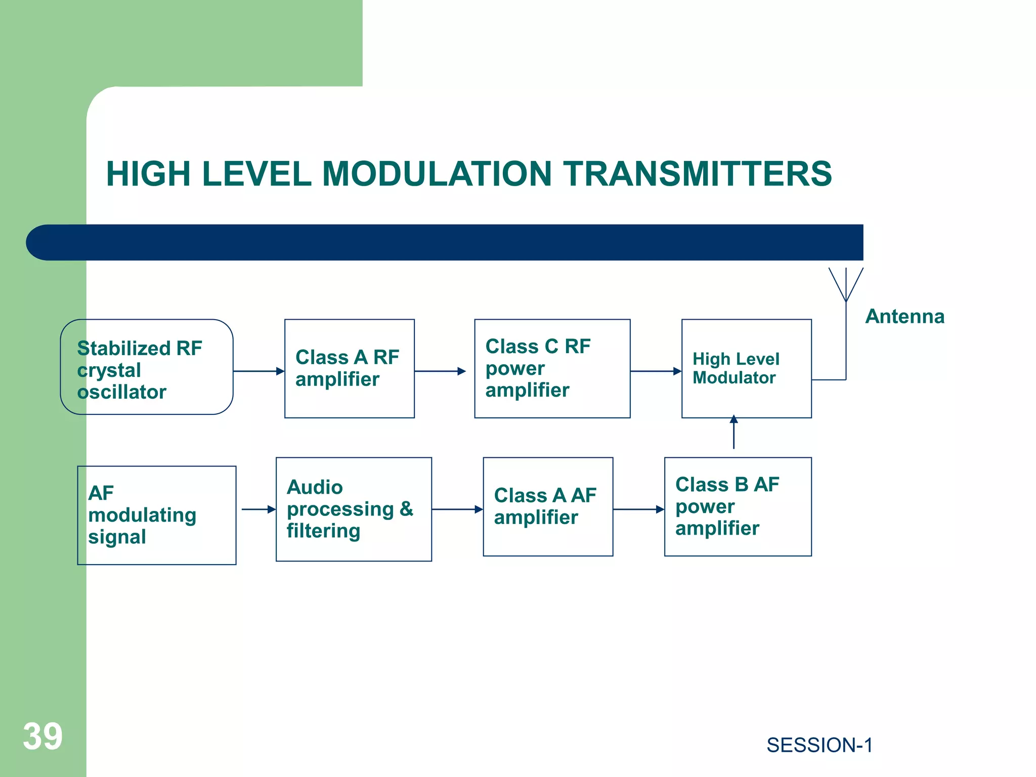
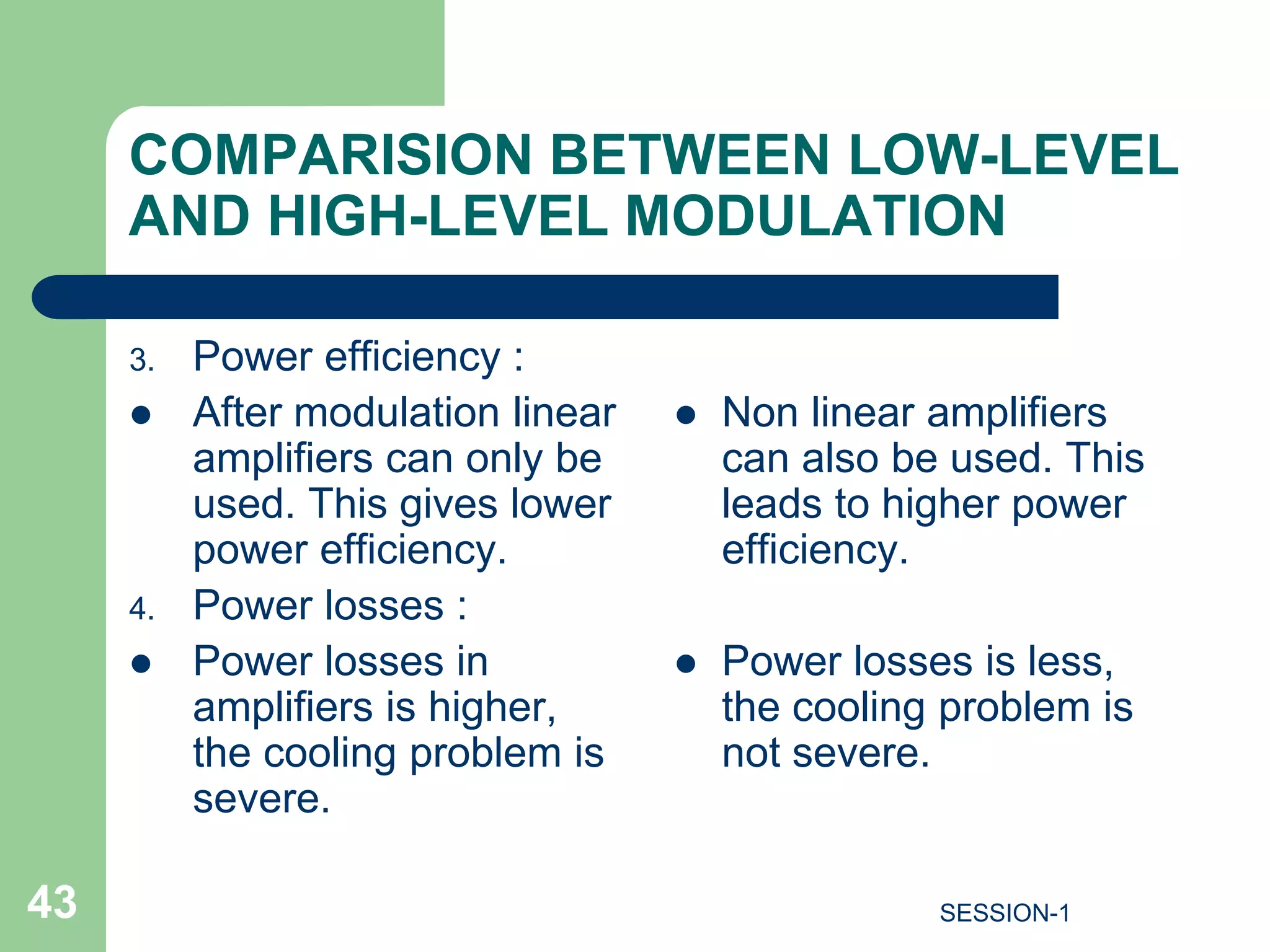
SlideShare a Scribd company logo
LECTURE ON AM/FM TRANSMITTER
PRESENTED BY
A.ABHISHEK REDDY
ASSISTANT PROFESSOR, MECS.
Mobile No.:8121444996
1 SESSION-1
UNIT-4 SYLLABUS
SESSION-1
2
Transmitters and Receivers:
(i)Classification of transmitters. High level and low level
AM transmitters.
(ii)FM transmitters.
(iii) Principle of operation of Tuned radio frequency
(TRF) and super heterodyne receivers.
(iv)Selection of RF amplifier. Choice of Intermediate
frequency. Image frequency and its rejection ratio
(v)Receiver characteristics: Sensitivity, Selectivity,
Fidelity,Double spotting, Automatic Gain Control.
Block diagram of communication
system
3 SESSION-1
Information or
Message
Transducer Transmitter Communication
Channel or
Medium
Information
in Electrical form
•It takes the information to be communicated in electrical
form and convert it into an electronic signal compatible
with the communication medium .
TRANSMITTER
4 SESSION-1
TRANSMITTER
 In this block diagram of communication
system, the upper section is called the
transmitting section.
5 SESSION-1
TRANSMITTER
 The main parts of transmitter are explained
as follows :
 Microphone : It converts sounds into
electrical signals in wires. It is the opposite
of a loudspeaker.
 Modulator : The audio signal is modulated
into the radio frequency carrier in this
modulator stage.
6 SESSION-1
TRANSMITTER
 Frequency generator : The frequency
generation stage will decide the frequency
on which the transmitter will operate.
 RF power amplifier : The power
amplification of the radio signal is carried
out in the final stage. It makes the signal
stronger so that it can be transmitted
through the channel over long distances.
7 SESSION-1
TRANSMITTER
 An antenna is a transducer which
converts electrical signals into
electromagnetic waves.
8 SESSION-1
BASIC BLOCKS OF TRANSMITTER
 Modulator
 RF oscillator
 Power amplifier
9 SESSION-1
BASIC FUNCTIONS OF TRANSMITTER
 Modulation
 Carrier generation
 Amplification (Power)
 It is an electronic unit which accepts the information
signal to be transmitted and converts it into an RF signal
capable of being transmitted over long distances .
10 SESSION-1
BASIC FUNCTIONS OF TRANSMITTER
Every transmitter has three basic functions as follows:
 The transmitter must generate a signal of correct
frequency at a desired point in the spectrum.
 Secondly it must provide some form of modulation to
modulate the carrier.
 Third it must provide sufficient power amplification in
order to carry the modulated signal to a long distance.
11 SESSION-1
CLASSIFICATION OF RADIO
TRANSMITTERS
1. According to the type of modulation used.
2. According to service involved.
3. According to the frequency range involved.
4. According to the power used.
12 SESSION-1
CLASSIFICATION BASED ON
TRANSMITTED FREQUENCY
 Low frequency (LF) transmitters (30 KHZ-
300KHZ)
 Medium frequency (MF) transmitters ( 300 KHZ-
3 MHZ)
 High frequency (HF) transmitters (3 MHZ-
30MHZ)
13 SESSION-1
CLASSIFICATION BASED ON
TRANSMITTED FREQUENCY
 Very high frequency (VHF) transmitters
(30MHZ-300 MHZ)
 Ultra high frequency (UHF) transmitters
(300 MHZ- 3GHZ)
 Microwave transmitters (>3GHZ)
14 SESSION-1
CLASSIFICATION BASED ON TYPE
OF SERVICE INVOLVED
 Radio telegraph transmitters.
i. AM/FM for point –to-point communication
ii. Transmission of messages are sent by means of dots and dashes
 Radio telephony transmitters.
i. used for transmission of telephone signals over long distances.
ii. AM/FM and short waves involve highly directional antennas
iii. Txd power is order of few KW
 Television transmitters.
i. Txmitting of picture/video signal—VSB
ii. Txmitting of sound—FM
iii. Both operate in VHF and UHF band with 7MHZ bandwidth
15 SESSION-1
CLASSIFICATION BASED ON TYPE
OF SERVICE INVOLVED
 Radar transmitters.
i. Pulse modulation : uses pulses as carrier and requires typically of 100KW
peak power in microwave band typically 3000MHz(10cm wavelength) or
10,000MHz(3cm wavelength)
ii. Continuous wave transmission : requires FM as carrier (doppler effect)
 Navigational transmitters.
i. For seas and air for blind landing of aircraft
ILS-instrumental landing system
GCA-ground control approach
16 SESSION-1
CLASSIFICATION BASED ON TYPES
OF MODULATION
 CW Transmitters
 AM Transmitters
 FM Transmitters
 SSB Transmitters
17 SESSION-1
CONTINIOUS WAVE (CW)
TRANSMITTERS
 It is a simple crystal oscillator circuit which generates a carrier signal of the desired
frequency.
 Information to be transmitted is expressed in a special form of code using dots and
dashes to represent letters of the alphabet and numbers.
18 SESSION-1
CONTINIOUS WAVE (CW)
TRANSMITTERS
 The key is a simple hand operated switch connected in emitter of the transistor.
 By closing the key we can turn on the crystal oscillator on and by opening the
key the oscillator is turned off.
 When the key is closed, the oscillator produces a sinusoidal signal at a
frequency equal to the crystal frequency, whereas with the key open, the
output of oscillator is zero.
 The key is opened and closed in order to produce zero output and dots or
dashes.
19 SESSION-1
CONTINIOUS WAVE (CW)
TRANSMITTERS
 Dots correspond to the short duration output whereas a dash corresponds to a
long duration output.
 The required messages can be transmitted using different combinations of
dots and dashes for different alphabets and letters.
 Length of dash is 3times the length of dots
 Spacing between letters in a word is equal to 3dots or 1 dash
20 SESSION-1
ADVANTAGES OF CW TRANSMITTER
 Simple to construct
 Compact and portable
 Can be operated on batteries
21 SESSION-1
DISADVANTAGES
 A skilled operator is required to convert the
message to be sent into a coded form of dots
and dashes.
 Long distance communication is not possible.
 Voice or picture can not be sent.
22 SESSION-1
DIFFERENT TYPES OF CWT
Straight Key
Keyer
“Bug” Keyer
23 SESSION-1
AM TRANSMITTER
 Amplitude modulation technique is used in AM
transmitters, here the amplitude of carrier is varied
in proportion with the amplitude of the modulating
signal, keeping its frequency and phase constant.
 Used in radio & TV broadcasting.
24 SESSION-1
AM TRANSMITTER
 In AM Transmitter, AM signal is transmitted
by a transmitter. The information is contained
in its amplitude variation.
25 SESSION-1
TYPES OF AM TRANSMITTERS
 Low Level modulation transmitters.
 High Level modulation transmitters.
26 SESSION-1
LOW LEVEL MODULATION
TRANSMITTERS
 The generation of AM wave takes place at a low power
level.
 The generated AM signal is then amplified using a chain
of linear amplifier ( A , AB or B).
Low Level
Modulator
Power
Amplifier
(Linear)
RF Carrier
Oscillator
Signal
Source
(Modulating
Signal)
27 SESSION-1
Class A
Buffer
amplifier
Modulator Linear
Amplifiers
STABILISED
RF
OSCILLATOR
Power
Amplifiers
Antenna
Class A AF
amplifier
Audio
processing &
filtering
AF
modulating
signal
LOW LEVEL MODULATION TRANSMITTERS
28 SESSION-1
LOW LEVEL MODULATION
TRANSMITTERS
 The RF oscillator produces the carrier signal.
The RF oscillator is stabilized in order to
maintain the frequency deviation within the
prescribed limit. The carrier frequency is
equal to the transmitter frequency.
 Usually the transmitter operates on assigned
frequencies or channels. Crystal provides the
best way to obtain the described frequency
with good stability.
29 SESSION-1
LOW LEVEL MODULATION
TRANSMITTERS
 We cannot use the LC oscillator because
they have low frequency stability.
 The carrier signal from the crystal oscillator is
applied to the modulator with a modulating
signal. At the output of the modulator we get
the AM wave.
30 SESSION-1
LOW LEVEL MODULATION
TRANSMITTERS
 The modulating signal is obtained from a
source such as a microphone and applied to
a buffer processing unit.
 The buffer is a class A amplifier which
isolates the AF source from the rest of high
power circuit and amplifies it to an adequate
level.
31 SESSION-1
LOW LEVEL MODULATION
TRANSMITTERS
 The amplified modulating signal is applied to
the modulator along with the carrier. At the
output of the modulator we get the AM wave.
 The AM signal is then amplified using a chain
of linear amplifier to raise the power level.
32 SESSION-1
LOW LEVEL MODULATION
TRANSMITTERS
 The linear amplifier can be class A, AB or B
type amplifiers. The linear amplifier are used
in order to avoid the wave form distortion in
AM wave.
 The amplitude modulated signal is then
transmitted using transmitted antenna.
33 SESSION-1
LOW LEVEL MODULATION
TRANSMITTERS
 The transistorized modulator circuits can be
used for low level modulator due to the low
power which is to be handled.
 The low level transmitter does not require a
large AF modulator power so its design is
simplified.
34 SESSION-1
LOW LEVEL MODULATION
TRANSMITTERS
 Overall efficiency is much lower compared to
high level modulation . This reduce to the
use of less efficient linear amplifiers.
35 SESSION-1
AUDIO PROCESSING
The AF modulating signal is passed
through an audio processing unit before
applying it to the modulator.
This block carries out some form of
“speech processing” in the form of filtering
and amplitude control.
The weak signals amplified automatically
with a higher gain and strong signals are
amplified with smaller gain. This will bring
all the signals to a sufficient level.
36 SESSION-1
HIGH LEVEL MODULATION
TRANSMITTERS
 The generation of AM wave takes place at high power
levels.
RF Carrier
Oscillator
Narrow Band
Power Amplifier
High Level
Modulator
Wide Band
Power
Amplifier
Signal
Source
(Modulating
Signal)
37 SESSION-1
HIGH LEVEL MODULATION
TRANSMITTERS
 Highly efficient class C amplifier are used in
high level modulation.
 Efficiency is more than low level modulation.
38 SESSION-1
Class A RF
amplifier
Stabilized RF
crystal
oscillator
Antenna
Class A AF
amplifier
Audio
processing &
filtering
AF
modulating
signal
Class C RF
power
amplifier
High Level
Modulator
Class B AF
power
amplifier
HIGH LEVEL MODULATION TRANSMITTERS
39 SESSION-1
HIGH LEVEL MODULATION
TRANSMITTERS
 Many of the AM transmitters use the high level
modulation technique.
 The crystal oscillator produces the required
carrier signal. The class A amplifier following the
oscillator acts as a buffer which isolates the
oscillator from the high power circuit.
40 SESSION-1
HIGH LEVEL MODULATION
TRANSMITTERS
 The output of this class A amplifier is applied
to a class C power amplifier. It raises the
power level of the carrier to an intermediately
high value.
 The AF modulating signal is applied to the
audio processing unit which processes this
signal as discussed in the previous section.
41 SESSION-1
COMPARISION BETWEEN LOW-LEVEL
AND HIGH-LEVEL MODULATION
1. Power level :
 Modulation is carried
out at low power level.
2. Amplifier stages:
 Need lesser amplifier
stages.
 Modulation is carried
out at high power
level.
 Need more amplifier
stages.
42 SESSION-1
COMPARISION BETWEEN LOW-LEVEL
AND HIGH-LEVEL MODULATION
3. Power efficiency :
 After modulation linear
amplifiers can only be
used. This gives lower
power efficiency.
4. Power losses :
 Power losses in
amplifiers is higher,
the cooling problem is
severe.
 Non linear amplifiers
can also be used. This
leads to higher power
efficiency.
 Power losses is less,
the cooling problem is
not severe.
43 SESSION-1
COMPARISION BETWEEN LOW-LEVEL
AND HIGH-LEVEL MODULATION
5. Applications :
 Used as higher power
broadcast transmitters.
 Used in TV
transmitters.
44 SESSION-1
SSB TRANSMITTERS
 PILOT CARRIER SYSTEM
 INDEPENDENT SIDEBAND SYSTEM(ISB)
45 SESSION-1
PILOT CARRIER SSB TRANSMITTERS
46 SESSION-1
ISB
47 SESSION-1
STANDARD BROADCAST BANDS
 AM(MEDIUM WAVE) : 550KHz-1650KHZ
 AM(SHORT WAVE) : 3-30MHz
 FM : 88MHz-108MHz
 TV : 54MHz-88MHz
174MHz-216MHz VHF
470MHz-890MHz(UHF)
48 SESSION-1
FM TRANSMITTERS
 Frequency modulation technique is used.
 In FM frequency of the carrier is varied in
proportion with the amplitude of the modulating
signal keeping its amplitude constant.
49 SESSION-1
FM TRANSMITTERS
 Used in radio, TV sound broadcasting &
police wireless transmission.
 In FM transmitter the FM signal is transmitted
by a transmitter. The information is contained
in its frequency variation.
50 SESSION-1
FM TRANSMITTERS
 The FCC has assigned a band of 20 MHz to
the commercial FM broad cast service.
 This band extends from 88 MHz to 108 MHz.
51 SESSION-1
FM TRANSMITTERS
 This 20 MHz band is divided in 100 channels,
each having a bandwidth of 200 KHz.
 For providing high quality reliable music the
maximum frequency deviation allowed is 75
KHz, with a maximum modulating signal
frequency of 15 KHz.
52 SESSION-1
METHODS OF FM GENERATION
Indirect Methods
Direct Methods
Methods of FM Generation
53 SESSION-1
DIRECT FM
 In direct FM generation the frequency of the
carrier is changed directly in proportion with the
modulating signal amplitude.
Types of Direct FM
 Reactance modulator
 Varactor diode modulator
54 SESSION-1
DIRECT FM
 These methods use a varactor diode or a
reactance transistor for presenting a variable
reactance across the frequency determining
circuit of an oscillator.
55 SESSION-1
DIRECT FM
Oscillator Tank
Circuit
Modulating
Signal
Variable reactance device
56 SESSION-1
DIRECT FM
 When the variable reactance of the device
varies with the modulating signal the
oscillator generator the corresponding FM
signal.
57 SESSION-1
DIRECT MODULATORS
 Few other direct modulators are:
 Varactor diode modulator.
 Reactance modulator.
 V.C.O. modulator.
 Stabilized reactance modulator.
 Cross by direct FM transmitters.
58 SESSION-1
REACTANCE MODULATOR
 In the reactance modulator, a transistor or
FET is operated as a variable reactance
(inductive or capacitive) device.
 This device is connected across the tuned
circuit of an oscillator.
 As the instantaneous value of modulating
voltage changes, the reactance offered by
the transistor or FET will change
proportionally.
59 SESSION-1
VARACTOR DIODE
 Here the voltage applied across the varactor diode
varies in proportion with the modulating voltage.
 This will vary the junction capacitance of the varactor
diode. The varactor diode appears in parallel with the
oscillator tuned circuit. Hence the oscillator frequency
will change with change in varactor diode capacitance
and FM wave is produced.
60 SESSION-1
ADVANTAGES OF DIRECT FM
MODULATION
 The main advantage of direct FM generation is
the simplicity of the modulators and their low
cost.
61 SESSION-1
DISADVANTAGES OF DIRECT
METHOD
 In the direct method of FM generation we have
to use the LC oscillator. The LC oscillator
frequency is not stable.
 Therefore its not possible to use such oscillator
for communication or broadcast purpose.
62 SESSION-1
DIRECT FM
 Therefore we have to use a scheme in which
we can use the crystal oscillator to control
the carrier frequency.
 Therefore we have to use the automatic
frequency control system.
63 SESSION-1
INDIRECT METHOD ( ARMSTRONG
METHOD)
 Here FM is obtained through phase modulation.
 A Crystal oscillator is used and hence the
frequency stability is very high.
 A narrow band PM signal is generated via DSB-
SC signal and a 90° phase shifted sub carrier
signal from a crystal oscillator.
64 SESSION-1
INDIRECT METHOD ( ARMSTRONG
METHOD)
 The integration of the modulating signal
makes the NBPM signal to NBFM signal.
 This NBFM signal is applied to a harmonic
generator (frequency multiplier) which will
increase both the carrier frequency and the
maximum deviation to the required.
65 SESSION-1
COMPARISION OF AM AND FM
BROADCASTING
AM Broadcasting
 It requires smaller
transmission
bandwidth.
 It can be operated in
low, medium and high
frequency bands.
 It has wider coverage.
FM Broadcasting
 It requires larger bandwidth.
 It needs to be operated in very
high and frequency bands.
 Its range is restricted to 50 km.
66 SESSION-1
COMPARISION OF AM AND FM
BROADCASTING
 The demodulation is
simple.
 The stereophonic
transmission is not
possible.
 The system has poor
noise performance.
 The process of
demodulation is
complex.
 In this, stereophonic
transmission is
possible.
 It has an improved
noise performance.
67 SESSION-1
REVISION
 What is Transmitter
 Classification of Transmitters
 Based on Type of modulation
 Based on Transmitted frequency
 AM Transmitters
 Types of AM transmitters
 Low Level modulation transmitter
 High Level modulation transmitter
 FM Transmitters
 Types of FM generation
 Direct method of FM generation
 Indirect method of FM generation
68 SESSION-1

More Related Content

What's hot

Chapter 3 am receivers
Chapter 3 am receiversChapter 3 am receivers
Chapter 3 am receiversmkazree
 
Amplitude modulation
Amplitude modulationAmplitude modulation
Amplitude modulation
sagarjaiswal0407
 
radio-wave-propagation
radio-wave-propagationradio-wave-propagation
radio-wave-propagation
ATTO RATHORE
 
Fm transmitter and receivers
Fm transmitter and receiversFm transmitter and receivers
Fm transmitter and receivers
Yogesh Bhargawa
 
HF Communication Basics Part 2
HF Communication Basics Part 2HF Communication Basics Part 2
HF Communication Basics Part 2
Afghanistan civil aviation institute
 
radio-wave-propagation-presentations
radio-wave-propagation-presentationsradio-wave-propagation-presentations
radio-wave-propagation-presentations
ATTO RATHORE
 
Broadside array vs end fire array
Broadside array vs end fire arrayBroadside array vs end fire array
Broadside array vs end fire array
AJAL A J
 
Fm transmitter
Fm transmitterFm transmitter
Fm transmitter
Arsalan Fakhar
 
wave propagation
wave propagationwave propagation
wave propagation
ATTO RATHORE
 
Travelling Wave Tube
Travelling Wave TubeTravelling Wave Tube
Travelling Wave Tube
Binita Khua
 
Digital modulation techniques...
Digital modulation techniques...Digital modulation techniques...
Digital modulation techniques...
Nidhi Baranwal
 
Phase modulation
Phase modulationPhase modulation
Phase modulationavocado1111
 
Receivers
ReceiversReceivers
Receivers
abhishek reddy
 
Radio receiver characteristics
Radio receiver characteristicsRadio receiver characteristics
Radio receiver characteristics
abhishek reddy
 
Angle modulation
Angle modulationAngle modulation
Angle modulationUmang Gupta
 
FM Demodulator
FM DemodulatorFM Demodulator

What's hot (20)

Pulse modulation
Pulse modulationPulse modulation
Pulse modulation
 
Chapter 3 am receivers
Chapter 3 am receiversChapter 3 am receivers
Chapter 3 am receivers
 
Amplitude modulation
Amplitude modulationAmplitude modulation
Amplitude modulation
 
radio-wave-propagation
radio-wave-propagationradio-wave-propagation
radio-wave-propagation
 
Amplitude modulation
Amplitude modulationAmplitude modulation
Amplitude modulation
 
Fm transmitter and receivers
Fm transmitter and receiversFm transmitter and receivers
Fm transmitter and receivers
 
Antenna (2)
Antenna (2)Antenna (2)
Antenna (2)
 
HF Communication Basics Part 2
HF Communication Basics Part 2HF Communication Basics Part 2
HF Communication Basics Part 2
 
radio-wave-propagation-presentations
radio-wave-propagation-presentationsradio-wave-propagation-presentations
radio-wave-propagation-presentations
 
Amplitude modulation
Amplitude modulationAmplitude modulation
Amplitude modulation
 
Broadside array vs end fire array
Broadside array vs end fire arrayBroadside array vs end fire array
Broadside array vs end fire array
 
Fm transmitter
Fm transmitterFm transmitter
Fm transmitter
 
wave propagation
wave propagationwave propagation
wave propagation
 
Travelling Wave Tube
Travelling Wave TubeTravelling Wave Tube
Travelling Wave Tube
 
Digital modulation techniques...
Digital modulation techniques...Digital modulation techniques...
Digital modulation techniques...
 
Phase modulation
Phase modulationPhase modulation
Phase modulation
 
Receivers
ReceiversReceivers
Receivers
 
Radio receiver characteristics
Radio receiver characteristicsRadio receiver characteristics
Radio receiver characteristics
 
Angle modulation
Angle modulationAngle modulation
Angle modulation
 
FM Demodulator
FM DemodulatorFM Demodulator
FM Demodulator
 

Similar to Radio transmitters

Am transmitter
Am transmitterAm transmitter
Am transmitter
AJAL A J
 
Communication system 1 chapter 3 - part 1
Communication system 1 chapter 3 - part 1Communication system 1 chapter 3 - part 1
Communication system 1 chapter 3 - part 1
BetelihemMesfin1
 
EST 130, Modulation
EST 130, ModulationEST 130, Modulation
EST 130, Modulation
CKSunith1
 
UNIT-4.pptx
UNIT-4.pptxUNIT-4.pptx
UNIT-4.pptx
LALITHAS47
 
Non Linear Signal Processing
Non Linear Signal ProcessingNon Linear Signal Processing
Non Linear Signal Processing
TejasPrajapati25
 
Chapter 2 amplitude_modulation
Chapter 2 amplitude_modulationChapter 2 amplitude_modulation
Chapter 2 amplitude_modulationmkazree
 
Chapter 2 amplitude_modulation
Chapter 2 amplitude_modulationChapter 2 amplitude_modulation
Chapter 2 amplitude_modulationHattori Sidek
 
Ppt on modulated and un modulated signal
Ppt on modulated and un modulated signalPpt on modulated and un modulated signal
Ppt on modulated and un modulated signal
pradeep kumar
 
EC6651 COMMUNICATION ENGINEERING UNIT 1
EC6651 COMMUNICATION ENGINEERING UNIT 1EC6651 COMMUNICATION ENGINEERING UNIT 1
EC6651 COMMUNICATION ENGINEERING UNIT 1
RMK ENGINEERING COLLEGE, CHENNAI
 
RADIO TRANSMITTERS.docx
RADIO TRANSMITTERS.docxRADIO TRANSMITTERS.docx
RADIO TRANSMITTERS.docx
CyprianObota
 
electronics and telecommunications: Amplitude modulation
electronics and telecommunications: Amplitude modulationelectronics and telecommunications: Amplitude modulation
electronics and telecommunications: Amplitude modulation
Arti Parab Academics
 
Unit- 3 Transmitters and Recivers.ppt
Unit- 3  Transmitters and Recivers.pptUnit- 3  Transmitters and Recivers.ppt
Unit- 3 Transmitters and Recivers.ppt
MATRUSRI ENGINEERING COLLEGE
 
Modulation types-amplitude,frequency,phase modulation,
Modulation types-amplitude,frequency,phase modulation,Modulation types-amplitude,frequency,phase modulation,
Modulation types-amplitude,frequency,phase modulation,
gayatri suthar
 
AMPLITUDE MODULATION & DEMODULATION TECHNIQUE
AMPLITUDE MODULATION & DEMODULATION TECHNIQUEAMPLITUDE MODULATION & DEMODULATION TECHNIQUE
AMPLITUDE MODULATION & DEMODULATION TECHNIQUE
IMTIAZ ALI AHMED
 
Physics Class 12 Communication Powerpoint presentation
Physics Class 12 Communication Powerpoint presentationPhysics Class 12 Communication Powerpoint presentation
Physics Class 12 Communication Powerpoint presentation
Bibin Vincent
 
Amplitude modulation and Demodulation Techniques
Amplitude modulation and Demodulation TechniquesAmplitude modulation and Demodulation Techniques
Amplitude modulation and Demodulation Techniques
Rich171473
 
COMMUNICATION SYSTEM_Module-2_part1 (1).pdf
COMMUNICATION SYSTEM_Module-2_part1 (1).pdfCOMMUNICATION SYSTEM_Module-2_part1 (1).pdf
COMMUNICATION SYSTEM_Module-2_part1 (1).pdf
COMPETITIVEGURUJI
 
Principles of communication systems for reference
Principles of communication systems for referencePrinciples of communication systems for reference
Principles of communication systems for reference
NatarajVijapur
 

Similar to Radio transmitters (20)

Am transmitter
Am transmitterAm transmitter
Am transmitter
 
Communication system 1 chapter 3 - part 1
Communication system 1 chapter 3 - part 1Communication system 1 chapter 3 - part 1
Communication system 1 chapter 3 - part 1
 
EST 130, Modulation
EST 130, ModulationEST 130, Modulation
EST 130, Modulation
 
UNIT-4.pptx
UNIT-4.pptxUNIT-4.pptx
UNIT-4.pptx
 
Non Linear Signal Processing
Non Linear Signal ProcessingNon Linear Signal Processing
Non Linear Signal Processing
 
Chapter 2 amplitude_modulation
Chapter 2 amplitude_modulationChapter 2 amplitude_modulation
Chapter 2 amplitude_modulation
 
Chapter 2 amplitude_modulation
Chapter 2 amplitude_modulationChapter 2 amplitude_modulation
Chapter 2 amplitude_modulation
 
Ppt on modulated and un modulated signal
Ppt on modulated and un modulated signalPpt on modulated and un modulated signal
Ppt on modulated and un modulated signal
 
EC6651 COMMUNICATION ENGINEERING UNIT 1
EC6651 COMMUNICATION ENGINEERING UNIT 1EC6651 COMMUNICATION ENGINEERING UNIT 1
EC6651 COMMUNICATION ENGINEERING UNIT 1
 
RADIO TRANSMITTERS.docx
RADIO TRANSMITTERS.docxRADIO TRANSMITTERS.docx
RADIO TRANSMITTERS.docx
 
electronics and telecommunications: Amplitude modulation
electronics and telecommunications: Amplitude modulationelectronics and telecommunications: Amplitude modulation
electronics and telecommunications: Amplitude modulation
 
Unit- 3 Transmitters and Recivers.ppt
Unit- 3  Transmitters and Recivers.pptUnit- 3  Transmitters and Recivers.ppt
Unit- 3 Transmitters and Recivers.ppt
 
3rd qrtr +++
3rd qrtr +++3rd qrtr +++
3rd qrtr +++
 
Modulation types-amplitude,frequency,phase modulation,
Modulation types-amplitude,frequency,phase modulation,Modulation types-amplitude,frequency,phase modulation,
Modulation types-amplitude,frequency,phase modulation,
 
AMPLITUDE MODULATION & DEMODULATION TECHNIQUE
AMPLITUDE MODULATION & DEMODULATION TECHNIQUEAMPLITUDE MODULATION & DEMODULATION TECHNIQUE
AMPLITUDE MODULATION & DEMODULATION TECHNIQUE
 
Physics Class 12 Communication Powerpoint presentation
Physics Class 12 Communication Powerpoint presentationPhysics Class 12 Communication Powerpoint presentation
Physics Class 12 Communication Powerpoint presentation
 
Amplitude modulation and Demodulation Techniques
Amplitude modulation and Demodulation TechniquesAmplitude modulation and Demodulation Techniques
Amplitude modulation and Demodulation Techniques
 
COMMUNICATION SYSTEM_Module-2_part1 (1).pdf
COMMUNICATION SYSTEM_Module-2_part1 (1).pdfCOMMUNICATION SYSTEM_Module-2_part1 (1).pdf
COMMUNICATION SYSTEM_Module-2_part1 (1).pdf
 
Principles of communication systems for reference
Principles of communication systems for referencePrinciples of communication systems for reference
Principles of communication systems for reference
 
FM Transmitter
FM TransmitterFM Transmitter
FM Transmitter
 

Recently uploaded

Architectural Portfolio Sean Lockwood
Architectural Portfolio Sean LockwoodArchitectural Portfolio Sean Lockwood
Architectural Portfolio Sean Lockwood
seandesed
 
Sachpazis:Terzaghi Bearing Capacity Estimation in simple terms with Calculati...
Sachpazis:Terzaghi Bearing Capacity Estimation in simple terms with Calculati...Sachpazis:Terzaghi Bearing Capacity Estimation in simple terms with Calculati...
Sachpazis:Terzaghi Bearing Capacity Estimation in simple terms with Calculati...
Dr.Costas Sachpazis
 
power quality voltage fluctuation UNIT - I.pptx
power quality voltage fluctuation UNIT - I.pptxpower quality voltage fluctuation UNIT - I.pptx
power quality voltage fluctuation UNIT - I.pptx
ViniHema
 
Top 10 Oil and Gas Projects in Saudi Arabia 2024.pdf
Top 10 Oil and Gas Projects in Saudi Arabia 2024.pdfTop 10 Oil and Gas Projects in Saudi Arabia 2024.pdf
Top 10 Oil and Gas Projects in Saudi Arabia 2024.pdf
Teleport Manpower Consultant
 
Courier management system project report.pdf
Courier management system project report.pdfCourier management system project report.pdf
Courier management system project report.pdf
Kamal Acharya
 
Hybrid optimization of pumped hydro system and solar- Engr. Abdul-Azeez.pdf
Hybrid optimization of pumped hydro system and solar- Engr. Abdul-Azeez.pdfHybrid optimization of pumped hydro system and solar- Engr. Abdul-Azeez.pdf
Hybrid optimization of pumped hydro system and solar- Engr. Abdul-Azeez.pdf
fxintegritypublishin
 
NO1 Uk best vashikaran specialist in delhi vashikaran baba near me online vas...
NO1 Uk best vashikaran specialist in delhi vashikaran baba near me online vas...NO1 Uk best vashikaran specialist in delhi vashikaran baba near me online vas...
NO1 Uk best vashikaran specialist in delhi vashikaran baba near me online vas...
Amil Baba Dawood bangali
 
Forklift Classes Overview by Intella Parts
Forklift Classes Overview by Intella PartsForklift Classes Overview by Intella Parts
Forklift Classes Overview by Intella Parts
Intella Parts
 
Final project report on grocery store management system..pdf
Final project report on grocery store management system..pdfFinal project report on grocery store management system..pdf
Final project report on grocery store management system..pdf
Kamal Acharya
 
TECHNICAL TRAINING MANUAL GENERAL FAMILIARIZATION COURSE
TECHNICAL TRAINING MANUAL   GENERAL FAMILIARIZATION COURSETECHNICAL TRAINING MANUAL   GENERAL FAMILIARIZATION COURSE
TECHNICAL TRAINING MANUAL GENERAL FAMILIARIZATION COURSE
DuvanRamosGarzon1
 
Democratizing Fuzzing at Scale by Abhishek Arya
Democratizing Fuzzing at Scale by Abhishek AryaDemocratizing Fuzzing at Scale by Abhishek Arya
Democratizing Fuzzing at Scale by Abhishek Arya
abh.arya
 
Water Industry Process Automation and Control Monthly - May 2024.pdf
Water Industry Process Automation and Control Monthly - May 2024.pdfWater Industry Process Automation and Control Monthly - May 2024.pdf
Water Industry Process Automation and Control Monthly - May 2024.pdf
Water Industry Process Automation & Control
 
Immunizing Image Classifiers Against Localized Adversary Attacks
Immunizing Image Classifiers Against Localized Adversary AttacksImmunizing Image Classifiers Against Localized Adversary Attacks
Immunizing Image Classifiers Against Localized Adversary Attacks
gerogepatton
 
ASME IX(9) 2007 Full Version .pdf
ASME IX(9)  2007 Full Version       .pdfASME IX(9)  2007 Full Version       .pdf
ASME IX(9) 2007 Full Version .pdf
AhmedHussein950959
 
The role of big data in decision making.
The role of big data in decision making.The role of big data in decision making.
The role of big data in decision making.
ankuprajapati0525
 
LIGA(E)11111111111111111111111111111111111111111.ppt
LIGA(E)11111111111111111111111111111111111111111.pptLIGA(E)11111111111111111111111111111111111111111.ppt
LIGA(E)11111111111111111111111111111111111111111.ppt
ssuser9bd3ba
 
Planning Of Procurement o different goods and services
Planning Of Procurement o different goods and servicesPlanning Of Procurement o different goods and services
Planning Of Procurement o different goods and services
JoytuBarua2
 
CFD Simulation of By-pass Flow in a HRSG module by R&R Consult.pptx
CFD Simulation of By-pass Flow in a HRSG module by R&R Consult.pptxCFD Simulation of By-pass Flow in a HRSG module by R&R Consult.pptx
CFD Simulation of By-pass Flow in a HRSG module by R&R Consult.pptx
R&R Consult
 
DESIGN A COTTON SEED SEPARATION MACHINE.docx
DESIGN A COTTON SEED SEPARATION MACHINE.docxDESIGN A COTTON SEED SEPARATION MACHINE.docx
DESIGN A COTTON SEED SEPARATION MACHINE.docx
FluxPrime1
 
weather web application report.pdf
weather web application report.pdfweather web application report.pdf
weather web application report.pdf
Pratik Pawar
 

Recently uploaded (20)

Architectural Portfolio Sean Lockwood
Architectural Portfolio Sean LockwoodArchitectural Portfolio Sean Lockwood
Architectural Portfolio Sean Lockwood
 
Sachpazis:Terzaghi Bearing Capacity Estimation in simple terms with Calculati...
Sachpazis:Terzaghi Bearing Capacity Estimation in simple terms with Calculati...Sachpazis:Terzaghi Bearing Capacity Estimation in simple terms with Calculati...
Sachpazis:Terzaghi Bearing Capacity Estimation in simple terms with Calculati...
 
power quality voltage fluctuation UNIT - I.pptx
power quality voltage fluctuation UNIT - I.pptxpower quality voltage fluctuation UNIT - I.pptx
power quality voltage fluctuation UNIT - I.pptx
 
Top 10 Oil and Gas Projects in Saudi Arabia 2024.pdf
Top 10 Oil and Gas Projects in Saudi Arabia 2024.pdfTop 10 Oil and Gas Projects in Saudi Arabia 2024.pdf
Top 10 Oil and Gas Projects in Saudi Arabia 2024.pdf
 
Courier management system project report.pdf
Courier management system project report.pdfCourier management system project report.pdf
Courier management system project report.pdf
 
Hybrid optimization of pumped hydro system and solar- Engr. Abdul-Azeez.pdf
Hybrid optimization of pumped hydro system and solar- Engr. Abdul-Azeez.pdfHybrid optimization of pumped hydro system and solar- Engr. Abdul-Azeez.pdf
Hybrid optimization of pumped hydro system and solar- Engr. Abdul-Azeez.pdf
 
NO1 Uk best vashikaran specialist in delhi vashikaran baba near me online vas...
NO1 Uk best vashikaran specialist in delhi vashikaran baba near me online vas...NO1 Uk best vashikaran specialist in delhi vashikaran baba near me online vas...
NO1 Uk best vashikaran specialist in delhi vashikaran baba near me online vas...
 
Forklift Classes Overview by Intella Parts
Forklift Classes Overview by Intella PartsForklift Classes Overview by Intella Parts
Forklift Classes Overview by Intella Parts
 
Final project report on grocery store management system..pdf
Final project report on grocery store management system..pdfFinal project report on grocery store management system..pdf
Final project report on grocery store management system..pdf
 
TECHNICAL TRAINING MANUAL GENERAL FAMILIARIZATION COURSE
TECHNICAL TRAINING MANUAL   GENERAL FAMILIARIZATION COURSETECHNICAL TRAINING MANUAL   GENERAL FAMILIARIZATION COURSE
TECHNICAL TRAINING MANUAL GENERAL FAMILIARIZATION COURSE
 
Democratizing Fuzzing at Scale by Abhishek Arya
Democratizing Fuzzing at Scale by Abhishek AryaDemocratizing Fuzzing at Scale by Abhishek Arya
Democratizing Fuzzing at Scale by Abhishek Arya
 
Water Industry Process Automation and Control Monthly - May 2024.pdf
Water Industry Process Automation and Control Monthly - May 2024.pdfWater Industry Process Automation and Control Monthly - May 2024.pdf
Water Industry Process Automation and Control Monthly - May 2024.pdf
 
Immunizing Image Classifiers Against Localized Adversary Attacks
Immunizing Image Classifiers Against Localized Adversary AttacksImmunizing Image Classifiers Against Localized Adversary Attacks
Immunizing Image Classifiers Against Localized Adversary Attacks
 
ASME IX(9) 2007 Full Version .pdf
ASME IX(9)  2007 Full Version       .pdfASME IX(9)  2007 Full Version       .pdf
ASME IX(9) 2007 Full Version .pdf
 
The role of big data in decision making.
The role of big data in decision making.The role of big data in decision making.
The role of big data in decision making.
 
LIGA(E)11111111111111111111111111111111111111111.ppt
LIGA(E)11111111111111111111111111111111111111111.pptLIGA(E)11111111111111111111111111111111111111111.ppt
LIGA(E)11111111111111111111111111111111111111111.ppt
 
Planning Of Procurement o different goods and services
Planning Of Procurement o different goods and servicesPlanning Of Procurement o different goods and services
Planning Of Procurement o different goods and services
 
CFD Simulation of By-pass Flow in a HRSG module by R&R Consult.pptx
CFD Simulation of By-pass Flow in a HRSG module by R&R Consult.pptxCFD Simulation of By-pass Flow in a HRSG module by R&R Consult.pptx
CFD Simulation of By-pass Flow in a HRSG module by R&R Consult.pptx
 
DESIGN A COTTON SEED SEPARATION MACHINE.docx
DESIGN A COTTON SEED SEPARATION MACHINE.docxDESIGN A COTTON SEED SEPARATION MACHINE.docx
DESIGN A COTTON SEED SEPARATION MACHINE.docx
 
weather web application report.pdf
weather web application report.pdfweather web application report.pdf
weather web application report.pdf
 

Radio transmitters

  • 1. LECTURE ON AM/FM TRANSMITTER PRESENTED BY A.ABHISHEK REDDY ASSISTANT PROFESSOR, MECS. Mobile No.:8121444996 1 SESSION-1
  • 2. UNIT-4 SYLLABUS SESSION-1 2 Transmitters and Receivers: (i)Classification of transmitters. High level and low level AM transmitters. (ii)FM transmitters. (iii) Principle of operation of Tuned radio frequency (TRF) and super heterodyne receivers. (iv)Selection of RF amplifier. Choice of Intermediate frequency. Image frequency and its rejection ratio (v)Receiver characteristics: Sensitivity, Selectivity, Fidelity,Double spotting, Automatic Gain Control.
  • 3. Block diagram of communication system 3 SESSION-1
  • 4. Information or Message Transducer Transmitter Communication Channel or Medium Information in Electrical form •It takes the information to be communicated in electrical form and convert it into an electronic signal compatible with the communication medium . TRANSMITTER 4 SESSION-1
  • 5. TRANSMITTER  In this block diagram of communication system, the upper section is called the transmitting section. 5 SESSION-1
  • 6. TRANSMITTER  The main parts of transmitter are explained as follows :  Microphone : It converts sounds into electrical signals in wires. It is the opposite of a loudspeaker.  Modulator : The audio signal is modulated into the radio frequency carrier in this modulator stage. 6 SESSION-1
  • 7. TRANSMITTER  Frequency generator : The frequency generation stage will decide the frequency on which the transmitter will operate.  RF power amplifier : The power amplification of the radio signal is carried out in the final stage. It makes the signal stronger so that it can be transmitted through the channel over long distances. 7 SESSION-1
  • 8. TRANSMITTER  An antenna is a transducer which converts electrical signals into electromagnetic waves. 8 SESSION-1
  • 9. BASIC BLOCKS OF TRANSMITTER  Modulator  RF oscillator  Power amplifier 9 SESSION-1
  • 10. BASIC FUNCTIONS OF TRANSMITTER  Modulation  Carrier generation  Amplification (Power)  It is an electronic unit which accepts the information signal to be transmitted and converts it into an RF signal capable of being transmitted over long distances . 10 SESSION-1
  • 11. BASIC FUNCTIONS OF TRANSMITTER Every transmitter has three basic functions as follows:  The transmitter must generate a signal of correct frequency at a desired point in the spectrum.  Secondly it must provide some form of modulation to modulate the carrier.  Third it must provide sufficient power amplification in order to carry the modulated signal to a long distance. 11 SESSION-1
  • 12. CLASSIFICATION OF RADIO TRANSMITTERS 1. According to the type of modulation used. 2. According to service involved. 3. According to the frequency range involved. 4. According to the power used. 12 SESSION-1
  • 13. CLASSIFICATION BASED ON TRANSMITTED FREQUENCY  Low frequency (LF) transmitters (30 KHZ- 300KHZ)  Medium frequency (MF) transmitters ( 300 KHZ- 3 MHZ)  High frequency (HF) transmitters (3 MHZ- 30MHZ) 13 SESSION-1
  • 14. CLASSIFICATION BASED ON TRANSMITTED FREQUENCY  Very high frequency (VHF) transmitters (30MHZ-300 MHZ)  Ultra high frequency (UHF) transmitters (300 MHZ- 3GHZ)  Microwave transmitters (>3GHZ) 14 SESSION-1
  • 15. CLASSIFICATION BASED ON TYPE OF SERVICE INVOLVED  Radio telegraph transmitters. i. AM/FM for point –to-point communication ii. Transmission of messages are sent by means of dots and dashes  Radio telephony transmitters. i. used for transmission of telephone signals over long distances. ii. AM/FM and short waves involve highly directional antennas iii. Txd power is order of few KW  Television transmitters. i. Txmitting of picture/video signal—VSB ii. Txmitting of sound—FM iii. Both operate in VHF and UHF band with 7MHZ bandwidth 15 SESSION-1
  • 16. CLASSIFICATION BASED ON TYPE OF SERVICE INVOLVED  Radar transmitters. i. Pulse modulation : uses pulses as carrier and requires typically of 100KW peak power in microwave band typically 3000MHz(10cm wavelength) or 10,000MHz(3cm wavelength) ii. Continuous wave transmission : requires FM as carrier (doppler effect)  Navigational transmitters. i. For seas and air for blind landing of aircraft ILS-instrumental landing system GCA-ground control approach 16 SESSION-1
  • 17. CLASSIFICATION BASED ON TYPES OF MODULATION  CW Transmitters  AM Transmitters  FM Transmitters  SSB Transmitters 17 SESSION-1
  • 18. CONTINIOUS WAVE (CW) TRANSMITTERS  It is a simple crystal oscillator circuit which generates a carrier signal of the desired frequency.  Information to be transmitted is expressed in a special form of code using dots and dashes to represent letters of the alphabet and numbers. 18 SESSION-1
  • 19. CONTINIOUS WAVE (CW) TRANSMITTERS  The key is a simple hand operated switch connected in emitter of the transistor.  By closing the key we can turn on the crystal oscillator on and by opening the key the oscillator is turned off.  When the key is closed, the oscillator produces a sinusoidal signal at a frequency equal to the crystal frequency, whereas with the key open, the output of oscillator is zero.  The key is opened and closed in order to produce zero output and dots or dashes. 19 SESSION-1
  • 20. CONTINIOUS WAVE (CW) TRANSMITTERS  Dots correspond to the short duration output whereas a dash corresponds to a long duration output.  The required messages can be transmitted using different combinations of dots and dashes for different alphabets and letters.  Length of dash is 3times the length of dots  Spacing between letters in a word is equal to 3dots or 1 dash 20 SESSION-1
  • 21. ADVANTAGES OF CW TRANSMITTER  Simple to construct  Compact and portable  Can be operated on batteries 21 SESSION-1
  • 22. DISADVANTAGES  A skilled operator is required to convert the message to be sent into a coded form of dots and dashes.  Long distance communication is not possible.  Voice or picture can not be sent. 22 SESSION-1
  • 23. DIFFERENT TYPES OF CWT Straight Key Keyer “Bug” Keyer 23 SESSION-1
  • 24. AM TRANSMITTER  Amplitude modulation technique is used in AM transmitters, here the amplitude of carrier is varied in proportion with the amplitude of the modulating signal, keeping its frequency and phase constant.  Used in radio & TV broadcasting. 24 SESSION-1
  • 25. AM TRANSMITTER  In AM Transmitter, AM signal is transmitted by a transmitter. The information is contained in its amplitude variation. 25 SESSION-1
  • 26. TYPES OF AM TRANSMITTERS  Low Level modulation transmitters.  High Level modulation transmitters. 26 SESSION-1
  • 27. LOW LEVEL MODULATION TRANSMITTERS  The generation of AM wave takes place at a low power level.  The generated AM signal is then amplified using a chain of linear amplifier ( A , AB or B). Low Level Modulator Power Amplifier (Linear) RF Carrier Oscillator Signal Source (Modulating Signal) 27 SESSION-1
  • 28. Class A Buffer amplifier Modulator Linear Amplifiers STABILISED RF OSCILLATOR Power Amplifiers Antenna Class A AF amplifier Audio processing & filtering AF modulating signal LOW LEVEL MODULATION TRANSMITTERS 28 SESSION-1
  • 29. LOW LEVEL MODULATION TRANSMITTERS  The RF oscillator produces the carrier signal. The RF oscillator is stabilized in order to maintain the frequency deviation within the prescribed limit. The carrier frequency is equal to the transmitter frequency.  Usually the transmitter operates on assigned frequencies or channels. Crystal provides the best way to obtain the described frequency with good stability. 29 SESSION-1
  • 30. LOW LEVEL MODULATION TRANSMITTERS  We cannot use the LC oscillator because they have low frequency stability.  The carrier signal from the crystal oscillator is applied to the modulator with a modulating signal. At the output of the modulator we get the AM wave. 30 SESSION-1
  • 31. LOW LEVEL MODULATION TRANSMITTERS  The modulating signal is obtained from a source such as a microphone and applied to a buffer processing unit.  The buffer is a class A amplifier which isolates the AF source from the rest of high power circuit and amplifies it to an adequate level. 31 SESSION-1
  • 32. LOW LEVEL MODULATION TRANSMITTERS  The amplified modulating signal is applied to the modulator along with the carrier. At the output of the modulator we get the AM wave.  The AM signal is then amplified using a chain of linear amplifier to raise the power level. 32 SESSION-1
  • 33. LOW LEVEL MODULATION TRANSMITTERS  The linear amplifier can be class A, AB or B type amplifiers. The linear amplifier are used in order to avoid the wave form distortion in AM wave.  The amplitude modulated signal is then transmitted using transmitted antenna. 33 SESSION-1
  • 34. LOW LEVEL MODULATION TRANSMITTERS  The transistorized modulator circuits can be used for low level modulator due to the low power which is to be handled.  The low level transmitter does not require a large AF modulator power so its design is simplified. 34 SESSION-1
  • 35. LOW LEVEL MODULATION TRANSMITTERS  Overall efficiency is much lower compared to high level modulation . This reduce to the use of less efficient linear amplifiers. 35 SESSION-1
  • 36. AUDIO PROCESSING The AF modulating signal is passed through an audio processing unit before applying it to the modulator. This block carries out some form of “speech processing” in the form of filtering and amplitude control. The weak signals amplified automatically with a higher gain and strong signals are amplified with smaller gain. This will bring all the signals to a sufficient level. 36 SESSION-1
  • 37. HIGH LEVEL MODULATION TRANSMITTERS  The generation of AM wave takes place at high power levels. RF Carrier Oscillator Narrow Band Power Amplifier High Level Modulator Wide Band Power Amplifier Signal Source (Modulating Signal) 37 SESSION-1
  • 38. HIGH LEVEL MODULATION TRANSMITTERS  Highly efficient class C amplifier are used in high level modulation.  Efficiency is more than low level modulation. 38 SESSION-1
  • 39. Class A RF amplifier Stabilized RF crystal oscillator Antenna Class A AF amplifier Audio processing & filtering AF modulating signal Class C RF power amplifier High Level Modulator Class B AF power amplifier HIGH LEVEL MODULATION TRANSMITTERS 39 SESSION-1
  • 40. HIGH LEVEL MODULATION TRANSMITTERS  Many of the AM transmitters use the high level modulation technique.  The crystal oscillator produces the required carrier signal. The class A amplifier following the oscillator acts as a buffer which isolates the oscillator from the high power circuit. 40 SESSION-1
  • 41. HIGH LEVEL MODULATION TRANSMITTERS  The output of this class A amplifier is applied to a class C power amplifier. It raises the power level of the carrier to an intermediately high value.  The AF modulating signal is applied to the audio processing unit which processes this signal as discussed in the previous section. 41 SESSION-1
  • 42. COMPARISION BETWEEN LOW-LEVEL AND HIGH-LEVEL MODULATION 1. Power level :  Modulation is carried out at low power level. 2. Amplifier stages:  Need lesser amplifier stages.  Modulation is carried out at high power level.  Need more amplifier stages. 42 SESSION-1
  • 43. COMPARISION BETWEEN LOW-LEVEL AND HIGH-LEVEL MODULATION 3. Power efficiency :  After modulation linear amplifiers can only be used. This gives lower power efficiency. 4. Power losses :  Power losses in amplifiers is higher, the cooling problem is severe.  Non linear amplifiers can also be used. This leads to higher power efficiency.  Power losses is less, the cooling problem is not severe. 43 SESSION-1
  • 44. COMPARISION BETWEEN LOW-LEVEL AND HIGH-LEVEL MODULATION 5. Applications :  Used as higher power broadcast transmitters.  Used in TV transmitters. 44 SESSION-1
  • 45. SSB TRANSMITTERS  PILOT CARRIER SYSTEM  INDEPENDENT SIDEBAND SYSTEM(ISB) 45 SESSION-1
  • 46. PILOT CARRIER SSB TRANSMITTERS 46 SESSION-1
  • 48. STANDARD BROADCAST BANDS  AM(MEDIUM WAVE) : 550KHz-1650KHZ  AM(SHORT WAVE) : 3-30MHz  FM : 88MHz-108MHz  TV : 54MHz-88MHz 174MHz-216MHz VHF 470MHz-890MHz(UHF) 48 SESSION-1
  • 49. FM TRANSMITTERS  Frequency modulation technique is used.  In FM frequency of the carrier is varied in proportion with the amplitude of the modulating signal keeping its amplitude constant. 49 SESSION-1
  • 50. FM TRANSMITTERS  Used in radio, TV sound broadcasting & police wireless transmission.  In FM transmitter the FM signal is transmitted by a transmitter. The information is contained in its frequency variation. 50 SESSION-1
  • 51. FM TRANSMITTERS  The FCC has assigned a band of 20 MHz to the commercial FM broad cast service.  This band extends from 88 MHz to 108 MHz. 51 SESSION-1
  • 52. FM TRANSMITTERS  This 20 MHz band is divided in 100 channels, each having a bandwidth of 200 KHz.  For providing high quality reliable music the maximum frequency deviation allowed is 75 KHz, with a maximum modulating signal frequency of 15 KHz. 52 SESSION-1
  • 53. METHODS OF FM GENERATION Indirect Methods Direct Methods Methods of FM Generation 53 SESSION-1
  • 54. DIRECT FM  In direct FM generation the frequency of the carrier is changed directly in proportion with the modulating signal amplitude. Types of Direct FM  Reactance modulator  Varactor diode modulator 54 SESSION-1
  • 55. DIRECT FM  These methods use a varactor diode or a reactance transistor for presenting a variable reactance across the frequency determining circuit of an oscillator. 55 SESSION-1
  • 57. DIRECT FM  When the variable reactance of the device varies with the modulating signal the oscillator generator the corresponding FM signal. 57 SESSION-1
  • 58. DIRECT MODULATORS  Few other direct modulators are:  Varactor diode modulator.  Reactance modulator.  V.C.O. modulator.  Stabilized reactance modulator.  Cross by direct FM transmitters. 58 SESSION-1
  • 59. REACTANCE MODULATOR  In the reactance modulator, a transistor or FET is operated as a variable reactance (inductive or capacitive) device.  This device is connected across the tuned circuit of an oscillator.  As the instantaneous value of modulating voltage changes, the reactance offered by the transistor or FET will change proportionally. 59 SESSION-1
  • 60. VARACTOR DIODE  Here the voltage applied across the varactor diode varies in proportion with the modulating voltage.  This will vary the junction capacitance of the varactor diode. The varactor diode appears in parallel with the oscillator tuned circuit. Hence the oscillator frequency will change with change in varactor diode capacitance and FM wave is produced. 60 SESSION-1
  • 61. ADVANTAGES OF DIRECT FM MODULATION  The main advantage of direct FM generation is the simplicity of the modulators and their low cost. 61 SESSION-1
  • 62. DISADVANTAGES OF DIRECT METHOD  In the direct method of FM generation we have to use the LC oscillator. The LC oscillator frequency is not stable.  Therefore its not possible to use such oscillator for communication or broadcast purpose. 62 SESSION-1
  • 63. DIRECT FM  Therefore we have to use a scheme in which we can use the crystal oscillator to control the carrier frequency.  Therefore we have to use the automatic frequency control system. 63 SESSION-1
  • 64. INDIRECT METHOD ( ARMSTRONG METHOD)  Here FM is obtained through phase modulation.  A Crystal oscillator is used and hence the frequency stability is very high.  A narrow band PM signal is generated via DSB- SC signal and a 90° phase shifted sub carrier signal from a crystal oscillator. 64 SESSION-1
  • 65. INDIRECT METHOD ( ARMSTRONG METHOD)  The integration of the modulating signal makes the NBPM signal to NBFM signal.  This NBFM signal is applied to a harmonic generator (frequency multiplier) which will increase both the carrier frequency and the maximum deviation to the required. 65 SESSION-1
  • 66. COMPARISION OF AM AND FM BROADCASTING AM Broadcasting  It requires smaller transmission bandwidth.  It can be operated in low, medium and high frequency bands.  It has wider coverage. FM Broadcasting  It requires larger bandwidth.  It needs to be operated in very high and frequency bands.  Its range is restricted to 50 km. 66 SESSION-1
  • 67. COMPARISION OF AM AND FM BROADCASTING  The demodulation is simple.  The stereophonic transmission is not possible.  The system has poor noise performance.  The process of demodulation is complex.  In this, stereophonic transmission is possible.  It has an improved noise performance. 67 SESSION-1
  • 68. REVISION  What is Transmitter  Classification of Transmitters  Based on Type of modulation  Based on Transmitted frequency  AM Transmitters  Types of AM transmitters  Low Level modulation transmitter  High Level modulation transmitter  FM Transmitters  Types of FM generation  Direct method of FM generation  Indirect method of FM generation 68 SESSION-1