Downloaded 218 times

![dBm to Watt
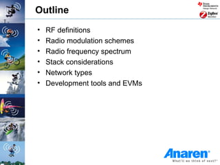
• About dBm and W
– Voltage Ratio aV = 20 log (P2/P1) [aV] = dB
– Power Ratio aP = 10 log (P2/P1) [aP] = dB
– Voltage Level V‘ = 20 log (V/1µV) [V‘] = dBµV
– Power Level P‘ = 10 log (P/1mW) [P‘] = dBm
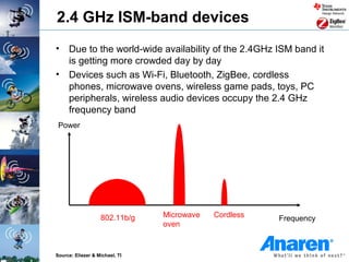
• Example: 25mW is the maximum allowed radiated (transmitted)
power in the EU SRD band
– P‘ = 10 log (25mW/1mW) = 10 * 1.39794 dBm ~ 14 dBm](https://image.slidesharecdn.com/airgettingstarted-130115110643-phpapp01/85/RF-Basics-Getting-Started-Guide-by-Anaren-6-320.jpg)

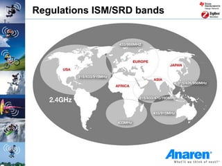

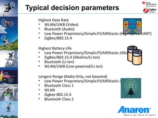
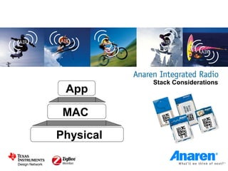
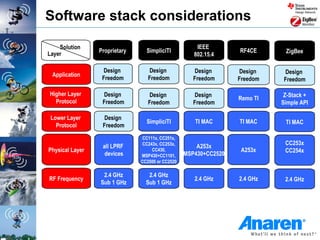
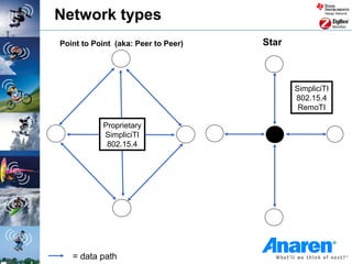
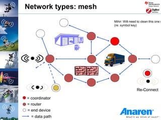
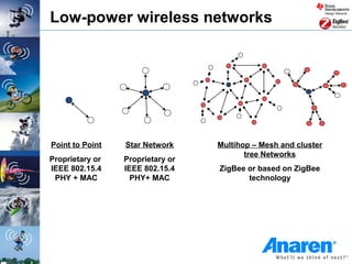
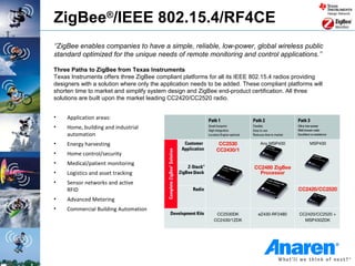
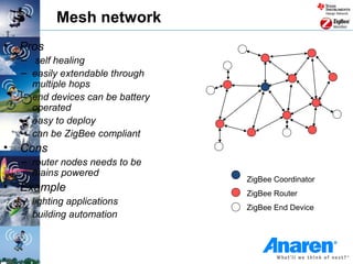
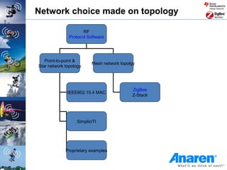
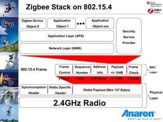
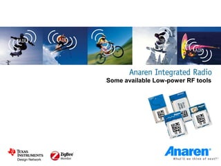
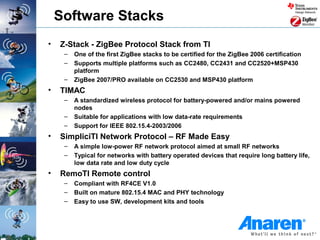
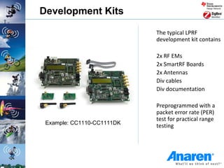
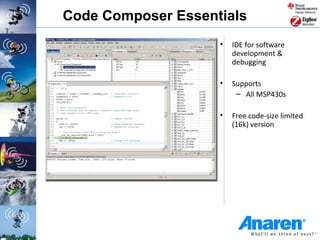


This document provides an overview of parameters and considerations for selecting a low-power wireless solution. It highlights products from Anaren's Integrated Radio module line, including how they fit into a typical low-power design. Development tools and evaluation modules are also discussed. Stack considerations cover aspects like application and protocol design freedom across various standards.


![RF Module Design - [Chapter 1] From Basics to RF Transceivers](https://cdn.slidesharecdn.com/ss_thumbnails/rfch1-150613070344-lva1-app6892-thumbnail.jpg?width=640&height=640&fit=bounds)