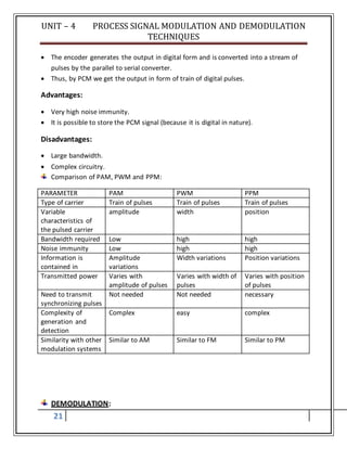
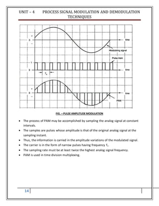
This document discusses various modulation and demodulation techniques. It begins by defining modulation as combining a low frequency signal with a high frequency carrier wave. It then describes different types of modulation including: amplitude modulation (AM), frequency modulation (FM), phase modulation (PM), pulse amplitude modulation (PAM), pulse width modulation (PWM), and pulse position modulation (PPM). It also discusses digital modulation techniques like pulse code modulation (PCM). For each technique, it provides the mathematical equations and diagrams to illustrate how the modulation works and compares their advantages and disadvantages. The document concludes by stating that demodulation is the reverse process of extracting the original information signal from the modulated carrier wave.

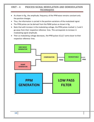
![UNIT – 4 PROCESS SIGNAL MODULATION AND DEMODULATION
TECHNIQUES
3
Where:
carrier frequency in Hertz is equal to ωc / 2 π
C is the carrier amplitude
φ is the phase of the signal at the start of the reference time
Both C and φ can be omitted to simplify the equation by changing C to "1" and φ to "0".
2. Modulating signal equations
The modulating waveform can either be a single tone. This can be represented by a cosine
waveform, or the modulating waveform could be a wide variety of frequencies - these can
be represented by a series of cosine waveforms added together in a linear fashion.
For the initial look at how the signal is formed, it is easiest to look at the equation for a
simple single tone waveform and then expand the concept to cover the more normal case.
Take a single tone waveform:
m (t) = M sin (ωm + φ)
Where:
modulating signal frequency in Hertz is equal to ωm / 2 π
M is the carrier amplitude
φ is the phase of the signal at the start of the reference time
Both C and φ can be omitted to simplify the equation by changing C to "1" and φ to "0".
It is worth noting that normally the modulating signal frequency is well below that of the carrier
frequency.
3. Overall modulated signal for a single tone
The equation for the overall modulated signal is obtained by multiplying the carrier and the
modulating signal together.
y (t) = [ A + m (t) ] . c (t)
The constant A is required as it represents the amplitude of the waveform.
Substituting in the individual relationships for the carrier and modulating signal, the overall
signal becomes:
y (t) = [ A + M cos (ωm t + φ ] . sin(ωc t)
The trigonometry can then be expanded out to give an equation that includes the components
of the signal:
y (t) = [ A + M cos (ωm t + φ ] . sin(ωc t)
This can be expanded out using the standard trigonometric rules:
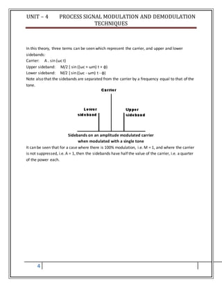
y (t) = A . sin (ωc t) + M/2 [ sin ((ωc + ωm) t + φ) + M/2 [ sin ((ωc - ωm) t - φ)](https://image.slidesharecdn.com/unit-4processsignalmodlationanddemodulationtechniques-180105115726/85/Unit-4-process-signal-modlation-and-demodulation-techniques-3-320.jpg)
![UNIT – 4 PROCESS SIGNAL MODULATION AND DEMODULATION
TECHNIQUES
20
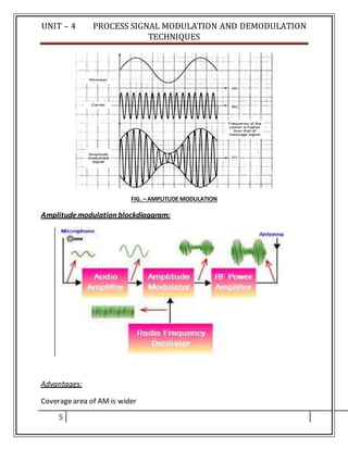
PCM consists of 3 steps to digitize an analog signal:
1. Sampling
2. Quantization
3. Binary encoding
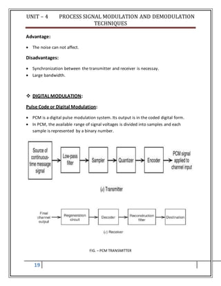
FIG. – SAMPLING, QUANTIZATION AND ENCODING
PCM transmitter is shown in fig. in fig., the message signal x(t) [fig. (a)] passes
through low pass filter to limit the maximum frequency of the signal and is given to
sample and hold circuit and then to quantizer.
Quantizer reduces the effect of noise and generates quantized PAM [fig. (d)] and it
will be the input of encoder (A to D converter).](https://image.slidesharecdn.com/unit-4processsignalmodlationanddemodulationtechniques-180105115726/85/Unit-4-process-signal-modlation-and-demodulation-techniques-20-320.jpg)