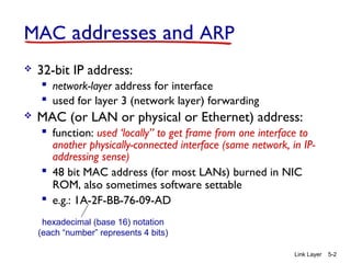
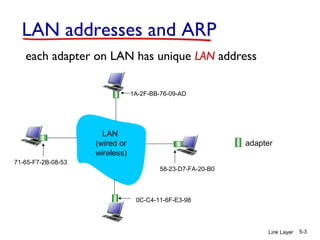
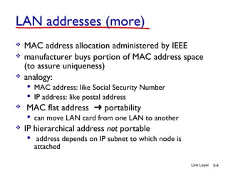
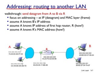
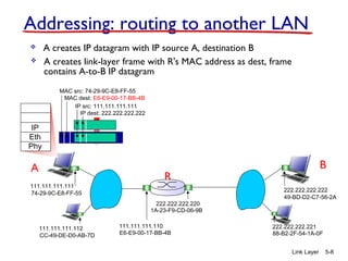
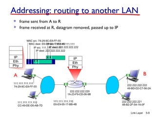
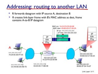
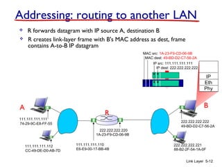
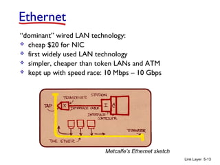
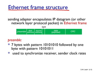
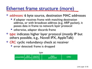
Chapter 5
Link Layer
Computer Networking: A Top Down
Approach
6th
edition
Jim Kurose, Keith Ross
Link Layer 5-1
Link Layer 5-2
MAC addresses and ARP
 32-bit IP address:
 network-layer address for interface
 used for layer 3 (network layer) forwarding
 MAC (or LAN or physical or Ethernet) address:
 function: used ‘locally” to get frame from one interface to
another physically-connected interface (same network, in IP-
addressing sense)
 48 bit MAC address (for most LANs) burned in NIC
ROM, also sometimes software settable
 e.g.: 1A-2F-BB-76-09-AD
hexadecimal (base 16) notation
(each “number” represents 4 bits)
Link Layer 5-3
LAN addresses and ARP
each adapter on LAN has unique LAN address
adapter
1A-2F-BB-76-09-AD
58-23-D7-FA-20-B0
0C-C4-11-6F-E3-98
71-65-F7-2B-08-53
LAN
(wired or
wireless)
Link Layer 5-4
LAN addresses (more)
 MAC address allocation administered by IEEE
 manufacturer buys portion of MAC address space
(to assure uniqueness)
 analogy:
 MAC address: like Social Security Number
 IP address: like postal address
 MAC flat address ➜ portability
 can move LAN card from one LAN to another
 IP hierarchical address not portable
 address depends on IP subnet to which node is
attached
Link Layer 5-5
ARP: address resolution protocol
ARP table: each IP node (host,
router) on LAN has table
 IP/MAC address
mappings for some LAN
nodes:
< IP address; MAC address; TTL>
 TTL (Time To Live):
time after which address
mapping will be
forgotten (typically 20
min)
Question: how to determine
interface’s MAC address,
knowing its IP address?
1A-2F-BB-76-09-AD
58-23-D7-FA-20-B0
0C-C4-11-6F-E3-98
71-65-F7-2B-08-53
LAN
137.196.7.23
137.196.7.78
137.196.7.14
137.196.7.88
Link Layer 5-6
ARP protocol: same LAN
 A wants to send datagram
to B
 B’s MAC address not in A’s
ARP table.
 A broadcasts ARP query
packet, containing B's IP
address
 dest MAC address = FF-FF-
FF-FF-FF-FF
 all nodes on LAN receive
ARP query
 B receives ARP packet,
replies to A with its (B's)
MAC address
 frame sent to A’s MAC
address (unicast)
 A caches (saves) IP-to-
MAC address pair in its
ARP table until
information becomes old
(times out)
 soft state: information that
times out (goes away)
unless refreshed
 ARP is “plug-and-play”:
 nodes create their ARP
tables without intervention
from net administrator
Link Layer 5-7
walkthrough: send datagram from A to B via R
 focus on addressing – at IP (datagram) and MAC layer (frame)
 assume A knows B’s IP address
 assume A knows IP address of first hop router, R (how?)
 assume A knows R’s MAC address (how?)
Addressing: routing to another LAN
R
1A-23-F9-CD-06-9B
222.222.222.220
111.111.111.110
E6-E9-00-17-BB-4BCC-49-DE-D0-AB-7D
111.111.111.112
111.111.111.111
74-29-9C-E8-FF-55
A
222.222.222.222
49-BD-D2-C7-56-2A
222.222.222.221
88-B2-2F-54-1A-0F
B
R
1A-23-F9-CD-06-9B
222.222.222.220
111.111.111.110
E6-E9-00-17-BB-4BCC-49-DE-D0-AB-7D
111.111.111.112
111.111.111.111
74-29-9C-E8-FF-55
A
222.222.222.222
49-BD-D2-C7-56-2A
222.222.222.221
88-B2-2F-54-1A-0F
B
Link Layer 5-8
Addressing: routing to another LAN
IP
Eth
Phy
IP src: 111.111.111.111
IP dest: 222.222.222.222
 A creates IP datagram with IP source A, destination B
 A creates link-layer frame with R's MAC address as dest, frame
contains A-to-B IP datagram
MAC src: 74-29-9C-E8-FF-55
MAC dest: E6-E9-00-17-BB-4B
R
1A-23-F9-CD-06-9B
222.222.222.220
111.111.111.110
E6-E9-00-17-BB-4BCC-49-DE-D0-AB-7D
111.111.111.112
111.111.111.111
74-29-9C-E8-FF-55
A
222.222.222.222
49-BD-D2-C7-56-2A
222.222.222.221
88-B2-2F-54-1A-0F
B
Link Layer 5-9
Addressing: routing to another LAN
IP
Eth
Phy
 frame sent from A to R
IP
Eth
Phy
 frame received at R, datagram removed, passed up to IP
MAC src: 74-29-9C-E8-FF-55
MAC dest: E6-E9-00-17-BB-4B
IP src: 111.111.111.111
IP dest: 222.222.222.222
IP src: 111.111.111.111
IP dest: 222.222.222.222
R
1A-23-F9-CD-06-9B
222.222.222.220
111.111.111.110
E6-E9-00-17-BB-4BCC-49-DE-D0-AB-7D
111.111.111.112
111.111.111.111
74-29-9C-E8-FF-55
A
222.222.222.222
49-BD-D2-C7-56-2A
222.222.222.221
88-B2-2F-54-1A-0F
B
Link Layer 5-10
Addressing: routing to another LAN
IP src: 111.111.111.111
IP dest: 222.222.222.222
 R forwards datagram with IP source A, destination B
 R creates link-layer frame with B's MAC address as dest, frame
contains A-to-B IP datagram
MAC src: 1A-23-F9-CD-06-9B
MAC dest: 49-BD-D2-C7-56-2A
IP
Eth
Phy
IP
Eth
Phy
R
1A-23-F9-CD-06-9B
222.222.222.220
111.111.111.110
E6-E9-00-17-BB-4BCC-49-DE-D0-AB-7D
111.111.111.112
111.111.111.111
74-29-9C-E8-FF-55
A
222.222.222.222
49-BD-D2-C7-56-2A
222.222.222.221
88-B2-2F-54-1A-0F
B
Link Layer 5-11
Addressing: routing to another LAN
 R forwards datagram with IP source A, destination B
 R creates link-layer frame with B's MAC address as dest, frame
contains A-to-B IP datagram
IP src: 111.111.111.111
IP dest: 222.222.222.222
MAC src: 1A-23-F9-CD-06-9B
MAC dest: 49-BD-D2-C7-56-2A
IP
Eth
Phy
IP
Eth
Phy
R
1A-23-F9-CD-06-9B
222.222.222.220
111.111.111.110
E6-E9-00-17-BB-4BCC-49-DE-D0-AB-7D
111.111.111.112
111.111.111.111
74-29-9C-E8-FF-55
A
222.222.222.222
49-BD-D2-C7-56-2A
222.222.222.221
88-B2-2F-54-1A-0F
B
Link Layer 5-12
Addressing: routing to another LAN
 R forwards datagram with IP source A, destination B
 R creates link-layer frame with B's MAC address as dest, frame
contains A-to-B IP datagram
IP src: 111.111.111.111
IP dest: 222.222.222.222
MAC src: 1A-23-F9-CD-06-9B
MAC dest: 49-BD-D2-C7-56-2A
IP
Eth
Phy
Link Layer 5-13
Ethernet
“dominant” wired LAN technology:
 cheap $20 for NIC
 first widely used LAN technology
 simpler, cheaper than token LANs and ATM
 kept up with speed race: 10 Mbps – 10 Gbps
Metcalfe’s Ethernet sketch
Link Layer 5-14
Ethernet: physical topology
 bus: popular through mid 90s
 all nodes in same collision domain (can collide with each
other)
 star: prevails today
 active switch in center
 each “spoke” runs a (separate) Ethernet protocol (nodes
do not collide with each other)
switch
bus: coaxial cable
star
Link Layer 5-15
Ethernet frame structure
sending adapter encapsulates IP datagram (or other
network layer protocol packet) in Ethernet frame
preamble:
 7 bytes with pattern 10101010 followed by one
byte with pattern 10101011
 used to synchronize receiver, sender clock rates
dest.
address
source
address
data
(payload) CRCpreamble
type
Link Layer 5-16
Ethernet frame structure (more)
 addresses: 6 byte source, destination MAC addresses
 if adapter receives frame with matching destination
address, or with broadcast address (e.g. ARP packet), it
passes data in frame to network layer protocol
 otherwise, adapter discards frame
 type: indicates higher layer protocol (mostly IP but
others possible, e.g., Novell IPX, AppleTalk)
 CRC: cyclic redundancy check at receiver
 error detected: frame is dropped
dest.
address
source
address
data
(payload) CRCpreamble
type
Link Layer 5-17
Ethernet: unreliable, connectionless
 connectionless: no handshaking between sending and
receiving NICs
 unreliable: receiving NIC doesnt send acks or nacks
to sending NIC
 data in dropped frames recovered only if initial
sender uses higher layer rdt (e.g., TCP), otherwise
dropped data lost
 Ethernet’s MAC protocol: unslotted CSMA/CD wth
binary backoff
Link Layer 5-18
Ethernet switch
 link-layer device: takes an active role
 store, forward Ethernet frames
 examine incoming frame’s MAC address,
selectively forward frame to one-or-more
outgoing links when frame is to be forwarded on
segment, uses CSMA/CD to access segment
 transparent
 hosts are unaware of presence of switches
 plug-and-play, self-learning
 switches do not need to be configured
Link Layer 5-19
Switch: multiple simultaneous transmissions
 hosts have dedicated, direct
connection to switch
 switches buffer packets
 Ethernet protocol used on each
incoming link, but no collisions;
full duplex
 each link is its own collision
domain
 switching: A-to-A’ and B-to-B’
can transmit simultaneously,
without collisions switch with six interfaces
(1,2,3,4,5,6)
A
A’
B
B’ C
C’
1 2
345
6
Link Layer 5-20
Switch forwarding table
Q: how does switch know A’
reachable via interface 4, B’
reachable via interface 5?
switch with six interfaces
(1,2,3,4,5,6)
A
A’
B
B’ C
C’
1 2
345
6 A: each switch has a switch
table, each entry:
 (MAC address of host, interface to
reach host, time stamp)
 looks like a routing table!
Q: how are entries created,
maintained in switch table?
 something like a routing protocol?
A
A’
B
B’ C
C’
1 2
345
6
Link Layer 5-21
Switch: self-learning
 switch learns which hosts
can be reached through
which interfaces
 when frame received,
switch “learns”
location of sender:
incoming LAN segment
 records sender/location
pair in switch table
A A’
Source: A
Dest: A’
MAC addr interface TTL
Switch table
(initially empty)
A 1 60
A
A’
B
B’ C
C’
1 2
345
6
Link Layer 5-22
Self-learning, forwarding: example
A A’
Source: A
Dest: A’
MAC addr interface TTL
switch table
(initially empty)
A 1 60
A A’A A’A A’A A’A A’
 frame destination, A’,
locaton unknown: flood
A’ A
 destination A location
known:
A’ 4 60
selectively send
on just one link
Link Layer 5-23
Interconnecting switches
 switches can be connected together
Q: sending from A to G - how does S1 know to
forward frame destined to F via S4 and S3?
A: self learning! (works exactly the same as in single-
switch case!)
A
B
S1
C D
E
F
S2
S4
S3
H
I
G
Link Layer 5-24
Self-learning multi-switch example
Suppose C sends frame to I, I responds to C
 Q: show switch tables and packet forwarding in S1, S2, S3, S4
A
B
S1
C D
E
F
S2
S4
S3
H
I
G
Link Layer 5-25
Institutional network
to external
network
router
IP subnet
mail server
web server
Link Layer 5-26
Switches vs. routers
both are store-and-forward:
routers: network-layer
devices (examine network-
layer headers)
switches: link-layer devices
(examine link-layer headers)
both have forwarding tables:
routers: compute tables using
routing algorithms, IP
addresses
switches: learn forwarding
table using flooding, learning,
MAC addresses
application
transport
network
link
physical
network
link
physical
link
physical
switch
datagram
application
transport
network
link
physical
frame
frame
frame
datagram
Link Layer 5-27
VLANs: motivation
consider:
 CS user moves office to
EE, but wants connect to
CS switch?
 single broadcast domain:
 all layer-2 broadcast
traffic (ARP, DHCP,
unknown location of
destination MAC
address) must cross
entire LAN
 security/privacy,
efficiency issues
Computer
Science Electrical
Engineering
Computer
Engineering
Link Layer 5-28
VLANs
port-based VLAN: switch ports
grouped (by switch management
software) so that single physical
switch ……
switch(es) supporting
VLAN capabilities can
be configured to
define multiple virtual
LANS over single
physical LAN
infrastructure.
Virtual Local
Area Network
1
8
9
16102
7
…
Electrical Engineering
(VLAN ports 1-8)
Computer Science
(VLAN ports 9-15)
15
…
Electrical Engineering
(VLAN ports 1-8)
…
1
82
7 9
1610
15
…
Computer Science
(VLAN ports 9-16)
… operates as multiple virtual switches
Link Layer 5-29
Port-based VLAN
1
8
9
16102
7
…
Electrical Engineering
(VLAN ports 1-8)
Computer Science
(VLAN ports 9-15)
15
…
 traffic isolation: frames to/from
ports 1-8 can only reach ports
1-8
 can also define VLAN based on
MAC addresses of endpoints,
rather than switch port
 dynamic membership: ports
can be dynamically assigned
among VLANs
router
 forwarding between VLANS: done via
routing (just as with separate
switches)
 in practice vendors sell combined
switches plus routers
Link Layer 5-30
VLANS spanning multiple switches
 trunk port: carries frames between VLANS defined over
multiple physical switches
 frames forwarded within VLAN between switches can’t be vanilla
802.1 frames (must carry VLAN ID info)
 802.1q protocol adds/removed additional header fields for frames
forwarded between trunk ports
1
8
9
102
7
…
Electrical Engineering
(VLAN ports 1-8)
Computer Science
(VLAN ports 9-15)
15
…
2
73
Ports 2,3,5 belong to EE VLAN
Ports 4,6,7,8 belong to CS VLAN
5
4 6 816
1
Link Layer 5-31
Synthesis: a day in the life of a web request
 journey down protocol stack complete!
 application, transport, network, link
 putting-it-all-together: synthesis!
 goal: identify, review, understand protocols (at all
layers) involved in seemingly simple scenario:
requesting www page
 scenario: student attaches laptop to campus network,
requests/receives www.google.com
Link Layer 5-32
A day in the life: scenario
Comcast network
68.80.0.0/13
Google’s network
64.233.160.0/1964.233.169.105
web server
DNS server
school network
68.80.2.0/24
web page
browser
router
(runs DHCP)
Link Layer 5-33
A day in the life… connecting to the Internet
 connecting laptop needs to
get its own IP address, addr
of first-hop router, addr of
DNS server: use DHCP
DHCP
UDP
IP
Eth
Phy
DHCP
DHCP
DHCP
DHCP
DHCP
DHCP
UDP
IP
Eth
Phy
DHCP
DHCP
DHCP
DHCPDHCP
 DHCP request encapsulated
in UDP, encapsulated in IP,
encapsulated in 802.3
Ethernet
 Ethernet frame broadcast
(dest: FFFFFFFFFFFF) on
LAN, received at router
running DHCP server
 Ethernet demuxed to IP
demuxed, UDP demuxed to
DHCP
router
(runs DHCP)
Link Layer 5-34
 DHCP server formulates
DHCP ACK containing
client’s IP address, IP
address of first-hop router
for client, name & IP
address of DNS server
DHCP
UDP
IP
Eth
Phy
DHCP
DHCP
DHCP
DHCP
DHCP
UDP
IP
Eth
Phy
DHCP
DHCP
DHCP
DHCP
DHCP
 encapsulation at DHCP
server, frame forwarded
(switch learning) through LAN,
demultiplexing at client
Client now has IP address, knows name & addr of DNS
server, IP address of its first-hop router
 DHCP client receives
DHCP ACK reply
A day in the life… connecting to the Internet
router
(runs DHCP)
Link Layer 5-35
A day in the life… ARP (before DNS, before HTTP)
 before sending HTTP request, need
IP address of www.google.com:
DNS
DNS
UDP
IP
Eth
Phy
DNS
DNS
DNS
 DNS query created, encapsulated in UDP,
encapsulated in IP, encapsulated in Eth. To
send frame to router, need MAC address of
router interface: ARP
 ARP query broadcast, received by
router, which replies with ARP
reply giving MAC address of
router interface
 client now knows MAC address
of first hop router, so can now
send frame containing DNS
query
ARP query
Eth
Phy
ARP
ARP
ARP reply
router
(runs DHCP)
Link Layer 5-36
DNS
UDP
IP
Eth
Phy
DNS
DNS
DNS
DNS
DNS
 IP datagram containing DNS
query forwarded via LAN
switch from client to 1st
hop
router
 IP datagram forwarded from
campus network into comcast
network, routed (tables created
by RIP, OSPF, IS-IS and/or BGP
routing protocols) to DNS server
 demux’ed to DNS server
 DNS server replies to client
with IP address of
www.google.com
Comcast network
68.80.0.0/13
DNS server
DNS
UDP
IP
Eth
Phy
DNS
DNS
DNS
DNS
A day in the life… using DNS
router
(runs DHCP)
Link Layer 5-37
A day in the life…TCP connection carrying HTTP
HTTP
TCP
IP
Eth
Phy
HTTP
 to send HTTP request,
client first opens TCP socket
to web server
 TCP SYN segment (step 1 in 3-
way handshake) inter-domain
routed to web server
 TCP connection established!64.233.169.105
web server
SYN
SYN
SYN
SYN
TCP
IP
Eth
Phy
SYN
SYN
SYN
SYNACK
SYNACK
SYNACK
SYNACK
SYNACK
SYNACK
SYNACK
 web server responds with TCP
SYNACK (step 2 in 3-way
handshake)
router
(runs DHCP)
Link Layer 5-38
A day in the life… HTTP request/reply
HTTP
TCP
IP
Eth
Phy
HTTP
 HTTP request sent into TCP
socket
 IP datagram containing HTTP
request routed to
www.google.com
 IP datagram containing HTTP reply
routed back to client64.233.169.105
web server
HTTP
TCP
IP
Eth
Phy
 web server responds with
HTTP reply (containing web
page)
HTTP
HTTP
HTTPHTTP
HTTP
HTTP
HTTP
HTTP
HTTP
HTTP
HTTP
HTTP
HTTP
 web page finally (!!!) displayed

Chapter 5 : Link Layer

  • 1.
    Chapter 5 Link Layer ComputerNetworking: A Top Down Approach 6th edition Jim Kurose, Keith Ross Link Layer 5-1
  • 2.
    Link Layer 5-2 MACaddresses and ARP  32-bit IP address:  network-layer address for interface  used for layer 3 (network layer) forwarding  MAC (or LAN or physical or Ethernet) address:  function: used ‘locally” to get frame from one interface to another physically-connected interface (same network, in IP- addressing sense)  48 bit MAC address (for most LANs) burned in NIC ROM, also sometimes software settable  e.g.: 1A-2F-BB-76-09-AD hexadecimal (base 16) notation (each “number” represents 4 bits)
  • 3.
    Link Layer 5-3 LANaddresses and ARP each adapter on LAN has unique LAN address adapter 1A-2F-BB-76-09-AD 58-23-D7-FA-20-B0 0C-C4-11-6F-E3-98 71-65-F7-2B-08-53 LAN (wired or wireless)
  • 4.
    Link Layer 5-4 LANaddresses (more)  MAC address allocation administered by IEEE  manufacturer buys portion of MAC address space (to assure uniqueness)  analogy:  MAC address: like Social Security Number  IP address: like postal address  MAC flat address ➜ portability  can move LAN card from one LAN to another  IP hierarchical address not portable  address depends on IP subnet to which node is attached
  • 5.
    Link Layer 5-5 ARP:address resolution protocol ARP table: each IP node (host, router) on LAN has table  IP/MAC address mappings for some LAN nodes: < IP address; MAC address; TTL>  TTL (Time To Live): time after which address mapping will be forgotten (typically 20 min) Question: how to determine interface’s MAC address, knowing its IP address? 1A-2F-BB-76-09-AD 58-23-D7-FA-20-B0 0C-C4-11-6F-E3-98 71-65-F7-2B-08-53 LAN 137.196.7.23 137.196.7.78 137.196.7.14 137.196.7.88
  • 6.
    Link Layer 5-6 ARPprotocol: same LAN  A wants to send datagram to B  B’s MAC address not in A’s ARP table.  A broadcasts ARP query packet, containing B's IP address  dest MAC address = FF-FF- FF-FF-FF-FF  all nodes on LAN receive ARP query  B receives ARP packet, replies to A with its (B's) MAC address  frame sent to A’s MAC address (unicast)  A caches (saves) IP-to- MAC address pair in its ARP table until information becomes old (times out)  soft state: information that times out (goes away) unless refreshed  ARP is “plug-and-play”:  nodes create their ARP tables without intervention from net administrator
  • 7.
    Link Layer 5-7 walkthrough:send datagram from A to B via R  focus on addressing – at IP (datagram) and MAC layer (frame)  assume A knows B’s IP address  assume A knows IP address of first hop router, R (how?)  assume A knows R’s MAC address (how?) Addressing: routing to another LAN R 1A-23-F9-CD-06-9B 222.222.222.220 111.111.111.110 E6-E9-00-17-BB-4BCC-49-DE-D0-AB-7D 111.111.111.112 111.111.111.111 74-29-9C-E8-FF-55 A 222.222.222.222 49-BD-D2-C7-56-2A 222.222.222.221 88-B2-2F-54-1A-0F B
  • 8.
    R 1A-23-F9-CD-06-9B 222.222.222.220 111.111.111.110 E6-E9-00-17-BB-4BCC-49-DE-D0-AB-7D 111.111.111.112 111.111.111.111 74-29-9C-E8-FF-55 A 222.222.222.222 49-BD-D2-C7-56-2A 222.222.222.221 88-B2-2F-54-1A-0F B Link Layer 5-8 Addressing:routing to another LAN IP Eth Phy IP src: 111.111.111.111 IP dest: 222.222.222.222  A creates IP datagram with IP source A, destination B  A creates link-layer frame with R's MAC address as dest, frame contains A-to-B IP datagram MAC src: 74-29-9C-E8-FF-55 MAC dest: E6-E9-00-17-BB-4B
  • 9.
    R 1A-23-F9-CD-06-9B 222.222.222.220 111.111.111.110 E6-E9-00-17-BB-4BCC-49-DE-D0-AB-7D 111.111.111.112 111.111.111.111 74-29-9C-E8-FF-55 A 222.222.222.222 49-BD-D2-C7-56-2A 222.222.222.221 88-B2-2F-54-1A-0F B Link Layer 5-9 Addressing:routing to another LAN IP Eth Phy  frame sent from A to R IP Eth Phy  frame received at R, datagram removed, passed up to IP MAC src: 74-29-9C-E8-FF-55 MAC dest: E6-E9-00-17-BB-4B IP src: 111.111.111.111 IP dest: 222.222.222.222 IP src: 111.111.111.111 IP dest: 222.222.222.222
  • 10.
    R 1A-23-F9-CD-06-9B 222.222.222.220 111.111.111.110 E6-E9-00-17-BB-4BCC-49-DE-D0-AB-7D 111.111.111.112 111.111.111.111 74-29-9C-E8-FF-55 A 222.222.222.222 49-BD-D2-C7-56-2A 222.222.222.221 88-B2-2F-54-1A-0F B Link Layer 5-10 Addressing:routing to another LAN IP src: 111.111.111.111 IP dest: 222.222.222.222  R forwards datagram with IP source A, destination B  R creates link-layer frame with B's MAC address as dest, frame contains A-to-B IP datagram MAC src: 1A-23-F9-CD-06-9B MAC dest: 49-BD-D2-C7-56-2A IP Eth Phy IP Eth Phy
  • 11.
    R 1A-23-F9-CD-06-9B 222.222.222.220 111.111.111.110 E6-E9-00-17-BB-4BCC-49-DE-D0-AB-7D 111.111.111.112 111.111.111.111 74-29-9C-E8-FF-55 A 222.222.222.222 49-BD-D2-C7-56-2A 222.222.222.221 88-B2-2F-54-1A-0F B Link Layer 5-11 Addressing:routing to another LAN  R forwards datagram with IP source A, destination B  R creates link-layer frame with B's MAC address as dest, frame contains A-to-B IP datagram IP src: 111.111.111.111 IP dest: 222.222.222.222 MAC src: 1A-23-F9-CD-06-9B MAC dest: 49-BD-D2-C7-56-2A IP Eth Phy IP Eth Phy
  • 12.
    R 1A-23-F9-CD-06-9B 222.222.222.220 111.111.111.110 E6-E9-00-17-BB-4BCC-49-DE-D0-AB-7D 111.111.111.112 111.111.111.111 74-29-9C-E8-FF-55 A 222.222.222.222 49-BD-D2-C7-56-2A 222.222.222.221 88-B2-2F-54-1A-0F B Link Layer 5-12 Addressing:routing to another LAN  R forwards datagram with IP source A, destination B  R creates link-layer frame with B's MAC address as dest, frame contains A-to-B IP datagram IP src: 111.111.111.111 IP dest: 222.222.222.222 MAC src: 1A-23-F9-CD-06-9B MAC dest: 49-BD-D2-C7-56-2A IP Eth Phy
  • 13.
    Link Layer 5-13 Ethernet “dominant”wired LAN technology:  cheap $20 for NIC  first widely used LAN technology  simpler, cheaper than token LANs and ATM  kept up with speed race: 10 Mbps – 10 Gbps Metcalfe’s Ethernet sketch
  • 14.
    Link Layer 5-14 Ethernet:physical topology  bus: popular through mid 90s  all nodes in same collision domain (can collide with each other)  star: prevails today  active switch in center  each “spoke” runs a (separate) Ethernet protocol (nodes do not collide with each other) switch bus: coaxial cable star
  • 15.
    Link Layer 5-15 Ethernetframe structure sending adapter encapsulates IP datagram (or other network layer protocol packet) in Ethernet frame preamble:  7 bytes with pattern 10101010 followed by one byte with pattern 10101011  used to synchronize receiver, sender clock rates dest. address source address data (payload) CRCpreamble type
  • 16.
    Link Layer 5-16 Ethernetframe structure (more)  addresses: 6 byte source, destination MAC addresses  if adapter receives frame with matching destination address, or with broadcast address (e.g. ARP packet), it passes data in frame to network layer protocol  otherwise, adapter discards frame  type: indicates higher layer protocol (mostly IP but others possible, e.g., Novell IPX, AppleTalk)  CRC: cyclic redundancy check at receiver  error detected: frame is dropped dest. address source address data (payload) CRCpreamble type
  • 17.
    Link Layer 5-17 Ethernet:unreliable, connectionless  connectionless: no handshaking between sending and receiving NICs  unreliable: receiving NIC doesnt send acks or nacks to sending NIC  data in dropped frames recovered only if initial sender uses higher layer rdt (e.g., TCP), otherwise dropped data lost  Ethernet’s MAC protocol: unslotted CSMA/CD wth binary backoff
  • 18.
    Link Layer 5-18 Ethernetswitch  link-layer device: takes an active role  store, forward Ethernet frames  examine incoming frame’s MAC address, selectively forward frame to one-or-more outgoing links when frame is to be forwarded on segment, uses CSMA/CD to access segment  transparent  hosts are unaware of presence of switches  plug-and-play, self-learning  switches do not need to be configured
  • 19.
    Link Layer 5-19 Switch:multiple simultaneous transmissions  hosts have dedicated, direct connection to switch  switches buffer packets  Ethernet protocol used on each incoming link, but no collisions; full duplex  each link is its own collision domain  switching: A-to-A’ and B-to-B’ can transmit simultaneously, without collisions switch with six interfaces (1,2,3,4,5,6) A A’ B B’ C C’ 1 2 345 6
  • 20.
    Link Layer 5-20 Switchforwarding table Q: how does switch know A’ reachable via interface 4, B’ reachable via interface 5? switch with six interfaces (1,2,3,4,5,6) A A’ B B’ C C’ 1 2 345 6 A: each switch has a switch table, each entry:  (MAC address of host, interface to reach host, time stamp)  looks like a routing table! Q: how are entries created, maintained in switch table?  something like a routing protocol?
  • 21.
    A A’ B B’ C C’ 1 2 345 6 LinkLayer 5-21 Switch: self-learning  switch learns which hosts can be reached through which interfaces  when frame received, switch “learns” location of sender: incoming LAN segment  records sender/location pair in switch table A A’ Source: A Dest: A’ MAC addr interface TTL Switch table (initially empty) A 1 60
  • 22.
    A A’ B B’ C C’ 1 2 345 6 LinkLayer 5-22 Self-learning, forwarding: example A A’ Source: A Dest: A’ MAC addr interface TTL switch table (initially empty) A 1 60 A A’A A’A A’A A’A A’  frame destination, A’, locaton unknown: flood A’ A  destination A location known: A’ 4 60 selectively send on just one link
  • 23.
    Link Layer 5-23 Interconnectingswitches  switches can be connected together Q: sending from A to G - how does S1 know to forward frame destined to F via S4 and S3? A: self learning! (works exactly the same as in single- switch case!) A B S1 C D E F S2 S4 S3 H I G
  • 24.
    Link Layer 5-24 Self-learningmulti-switch example Suppose C sends frame to I, I responds to C  Q: show switch tables and packet forwarding in S1, S2, S3, S4 A B S1 C D E F S2 S4 S3 H I G
  • 25.
    Link Layer 5-25 Institutionalnetwork to external network router IP subnet mail server web server
  • 26.
    Link Layer 5-26 Switchesvs. routers both are store-and-forward: routers: network-layer devices (examine network- layer headers) switches: link-layer devices (examine link-layer headers) both have forwarding tables: routers: compute tables using routing algorithms, IP addresses switches: learn forwarding table using flooding, learning, MAC addresses application transport network link physical network link physical link physical switch datagram application transport network link physical frame frame frame datagram
  • 27.
    Link Layer 5-27 VLANs:motivation consider:  CS user moves office to EE, but wants connect to CS switch?  single broadcast domain:  all layer-2 broadcast traffic (ARP, DHCP, unknown location of destination MAC address) must cross entire LAN  security/privacy, efficiency issues Computer Science Electrical Engineering Computer Engineering
  • 28.
    Link Layer 5-28 VLANs port-basedVLAN: switch ports grouped (by switch management software) so that single physical switch …… switch(es) supporting VLAN capabilities can be configured to define multiple virtual LANS over single physical LAN infrastructure. Virtual Local Area Network 1 8 9 16102 7 … Electrical Engineering (VLAN ports 1-8) Computer Science (VLAN ports 9-15) 15 … Electrical Engineering (VLAN ports 1-8) … 1 82 7 9 1610 15 … Computer Science (VLAN ports 9-16) … operates as multiple virtual switches
  • 29.
    Link Layer 5-29 Port-basedVLAN 1 8 9 16102 7 … Electrical Engineering (VLAN ports 1-8) Computer Science (VLAN ports 9-15) 15 …  traffic isolation: frames to/from ports 1-8 can only reach ports 1-8  can also define VLAN based on MAC addresses of endpoints, rather than switch port  dynamic membership: ports can be dynamically assigned among VLANs router  forwarding between VLANS: done via routing (just as with separate switches)  in practice vendors sell combined switches plus routers
  • 30.
    Link Layer 5-30 VLANSspanning multiple switches  trunk port: carries frames between VLANS defined over multiple physical switches  frames forwarded within VLAN between switches can’t be vanilla 802.1 frames (must carry VLAN ID info)  802.1q protocol adds/removed additional header fields for frames forwarded between trunk ports 1 8 9 102 7 … Electrical Engineering (VLAN ports 1-8) Computer Science (VLAN ports 9-15) 15 … 2 73 Ports 2,3,5 belong to EE VLAN Ports 4,6,7,8 belong to CS VLAN 5 4 6 816 1
  • 31.
    Link Layer 5-31 Synthesis:a day in the life of a web request  journey down protocol stack complete!  application, transport, network, link  putting-it-all-together: synthesis!  goal: identify, review, understand protocols (at all layers) involved in seemingly simple scenario: requesting www page  scenario: student attaches laptop to campus network, requests/receives www.google.com
  • 32.
    Link Layer 5-32 Aday in the life: scenario Comcast network 68.80.0.0/13 Google’s network 64.233.160.0/1964.233.169.105 web server DNS server school network 68.80.2.0/24 web page browser
  • 33.
    router (runs DHCP) Link Layer5-33 A day in the life… connecting to the Internet  connecting laptop needs to get its own IP address, addr of first-hop router, addr of DNS server: use DHCP DHCP UDP IP Eth Phy DHCP DHCP DHCP DHCP DHCP DHCP UDP IP Eth Phy DHCP DHCP DHCP DHCPDHCP  DHCP request encapsulated in UDP, encapsulated in IP, encapsulated in 802.3 Ethernet  Ethernet frame broadcast (dest: FFFFFFFFFFFF) on LAN, received at router running DHCP server  Ethernet demuxed to IP demuxed, UDP demuxed to DHCP
  • 34.
    router (runs DHCP) Link Layer5-34  DHCP server formulates DHCP ACK containing client’s IP address, IP address of first-hop router for client, name & IP address of DNS server DHCP UDP IP Eth Phy DHCP DHCP DHCP DHCP DHCP UDP IP Eth Phy DHCP DHCP DHCP DHCP DHCP  encapsulation at DHCP server, frame forwarded (switch learning) through LAN, demultiplexing at client Client now has IP address, knows name & addr of DNS server, IP address of its first-hop router  DHCP client receives DHCP ACK reply A day in the life… connecting to the Internet
  • 35.
    router (runs DHCP) Link Layer5-35 A day in the life… ARP (before DNS, before HTTP)  before sending HTTP request, need IP address of www.google.com: DNS DNS UDP IP Eth Phy DNS DNS DNS  DNS query created, encapsulated in UDP, encapsulated in IP, encapsulated in Eth. To send frame to router, need MAC address of router interface: ARP  ARP query broadcast, received by router, which replies with ARP reply giving MAC address of router interface  client now knows MAC address of first hop router, so can now send frame containing DNS query ARP query Eth Phy ARP ARP ARP reply
  • 36.
    router (runs DHCP) Link Layer5-36 DNS UDP IP Eth Phy DNS DNS DNS DNS DNS  IP datagram containing DNS query forwarded via LAN switch from client to 1st hop router  IP datagram forwarded from campus network into comcast network, routed (tables created by RIP, OSPF, IS-IS and/or BGP routing protocols) to DNS server  demux’ed to DNS server  DNS server replies to client with IP address of www.google.com Comcast network 68.80.0.0/13 DNS server DNS UDP IP Eth Phy DNS DNS DNS DNS A day in the life… using DNS
  • 37.
    router (runs DHCP) Link Layer5-37 A day in the life…TCP connection carrying HTTP HTTP TCP IP Eth Phy HTTP  to send HTTP request, client first opens TCP socket to web server  TCP SYN segment (step 1 in 3- way handshake) inter-domain routed to web server  TCP connection established!64.233.169.105 web server SYN SYN SYN SYN TCP IP Eth Phy SYN SYN SYN SYNACK SYNACK SYNACK SYNACK SYNACK SYNACK SYNACK  web server responds with TCP SYNACK (step 2 in 3-way handshake)
  • 38.
    router (runs DHCP) Link Layer5-38 A day in the life… HTTP request/reply HTTP TCP IP Eth Phy HTTP  HTTP request sent into TCP socket  IP datagram containing HTTP request routed to www.google.com  IP datagram containing HTTP reply routed back to client64.233.169.105 web server HTTP TCP IP Eth Phy  web server responds with HTTP reply (containing web page) HTTP HTTP HTTPHTTP HTTP HTTP HTTP HTTP HTTP HTTP HTTP HTTP HTTP  web page finally (!!!) displayed