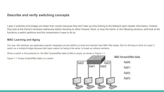
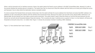
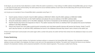
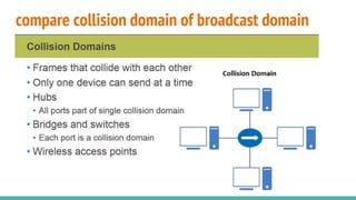
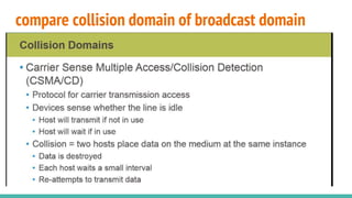
SlideShare a Scribd company logo
1 of 17
LAN Switching Technologies
CCNA Routing and Switching Complete Review Guide
Eng. Mohamed Selim
Describe and verify switching concepts
Layer 2 switches and bridges are faster than routers because they don't take up time looking at the Network layer header information. Instead,
they look at the frame's hardware addresses before deciding to either forward, flood, or drop the frame. In the following sections, we'll look at the
functions a switch performs and the components it uses to do so.
MAC Learning and Aging
Our new, fast switches use application-specific integrated circuits (ASICs) to build and maintain their MAC filter tables. But it's still okay to think of a layer 2
switch as a multiport bridge because their basic reason for being is the same: to break up collision domains.
When a switch is first powered on, the MAC forward/filter table (CAM) is empty, as shown in Figure 1.1
Figure 1.1: Empty forward/filter table on a switch
When a device transmits and an interface receives a frame, the switch places the frame's source address in the MAC forward/filter table, allowing it to refer to
the precise interface the sending device is located on. The switch then has no choice but to flood the network with this frame out of every port except the source
port because it has no idea where the destination device is actually located.
If a device answers this flooded frame and sends a frame back, then the switch will take the source address from that frame and place that MAC address in its
database as well, associating this address with the interface that received the frame. Because the switch now has both of the relevant MAC addresses in its
filtering table, the two devices can now make a point-to-point connection. The switch doesn't need to flood the frame as it did the first time because now the
frames can and will only be forwarded between these two devices. This is exactly why layer 2 switches are so superior to hubs. In a hub network, all frames are
forwarded out all ports every time—no matter what. Figure 1.2 shows the processes involved in building a MAC database.
Figure 1.2: How switches learn hosts’ locations
In this figure, you can see four hosts attached to a switch. When the switch is powered on, it has nothing in its MAC address forward/filter table, just as in Figure
1.1. But when the hosts start communicating, the switch places the source hardware address of each frame into the table along with the port that the frame's
source address corresponds to.
Let me give you an example of how a forward/filter table is populated using Figure 1.2:
1. Host A sends a frame to Host B. Host A's MAC address is 0000.8c01.000A; Host B's MAC address is 0000.8c01.000B.
2. The switch receives the frame on the Fa0/0 interface and places the source address in the MAC address table.
3. Since the destination address isn't in the MAC database, the frame is forwarded out all interfaces except the source port.
4. Host B receives the frame and responds to Host A. The switch receives this frame on interface Fa0/1 and places the source hardware
address in the MAC database.
5. Host A and Host B can now make a point-to-point connection and only these specific devices will receive the frames. Hosts C and D
won't see the frames, nor will their MAC addresses be found in the database because they haven't sent a frame to the switch yet.
If Host A and Host B don't communicate to the switch again within a certain time period, the switch will flush their entries from the database to keep it as current
as possible.
Frame Switching
When a frame arrives at a switch interface, the destination hardware address is compared to the forward/filter MAC database. If the destination hardware
address is known and listed in the database, the frame is only sent out of the appropriate exit interface. The switch won't transmit the frame out any interface
except for the destination interface, which preserves bandwidth on the other network segments. This process is called frame filtering.
Frame Flooding
If the destination hardware address isn't listed in the MAC database, then the frame will be flooded out all active interfaces except the interface it was received on.
If a device answers the flooded frame, the MAC database is then updated with the device's location—its correct interface.
If a host or server sends a broadcast on the LAN, by default, the switch will flood the frame out all active ports except the source port. Remember, the switch
creates smaller collision domains, but it's always still one large broadcast domain by default.
In Figure 1.3, Host A sends a data frame to Host D. What do you think the switch will do when it receives the frame from Host A?
Figure 1.4: Forward/filter table Figure 1.3: Forward/filter table
Since Host A's MAC address is not in the forward/filter table, the switch will add the source address and port to the MAC address table, then forward the frame to
Host D. It's really important to remember that the source MAC is always checked first to make sure it's in the CAM table. After that, if Host D's MAC address wasn't
found in the forward/filter table, the switch would've flooded the frame out all ports except for port Fa0/3 because that's the specific port the frame was received on.
MAC Address Table
Now let's take a look at the output that results from using a show mac address-table command:
Switch#sh mac address-table
But let's say the preceding switch received a frame with the following MAC addresses:
● Source MAC: 0005.dccb.d74b
● Destination MAC: 000a.f467.9e8c
How will the switch handle this frame? The right answer is that the destination MAC address will be found in the MAC address table and the frame will only be
forwarded out Fa0/3. Never forget that if the destination MAC address isn't found in the forward/filter table, the frame will be forwarded out all of the switch's ports
except for the one on which it was originally received in an attempt to locate the destination device. Now that you can see the MAC address table and how
switches add host addresses to the forward filter table, how do think we can secure it from unauthorized users?
Exam Essentials
Remember the three switch functions. Address learning, forward/filter decisions, and loop avoidance are the functions of a switch.
Remember the command show mac address-table. The command show mac address-table will show you the forward/filter table used on the LAN switch.
Interpret Ethernet frame format
The Data Link layer is responsible for combining bits into bytes and bytes into frames. Frames are used at the Data Link layer to encapsulate packets handed down
from the Network layer for transmission on a type of media access. In the following section, we'll discuss the format of these frames called Ethernet frames.
Ethernet Frames
The function of Ethernet stations is to pass data frames between each other using a group of bits known as a MAC frame format. This provides
error detection from a cyclic redundancy check (CRC). But remember—this is error detection, not error correction. An example of a typical Ethernet
frame used today is shown in Figure 1.5.
Figure 2.5: Typical Ethernet frame format
Note Encapsulating a frame within a different type of frame is called tunneling.
Following are the details of the various fields in the typical Ethernet frame type:
Preamble An alternating 1,0 pattern provides a 5 MHz clock at the start of each packet, which allows the receiving devices to lock the incoming bit stream.
Start Frame Delimiter (SFD)/Synch The preamble is seven octets and the SFD is one octet (synch). The SFD is 10101011, where the last pair of 1s allows the
receiver to come into the alternating 1,0 pattern somewhere in the middle and still sync up to detect the beginning of the data.
Destination Address (DA) This transmits a 48-bit value using the least significant bit (LSB) first. The DA is used by receiving stations to determine whether an
incoming packet is addressed to a particular node. The destination address can be an individual address or a broadcast or multicast MAC address. Remember that
a broadcast is all 1s—all Fs in hex—and is sent to all devices. A multicast is sent only to a similar subset of nodes on a network.
Source Address (SA) The SA is a 48-bit MAC address used to identify the transmitting device, and it uses the least significant bit first. Broadcast and multicast
address formats are illegal within the SA field.
Length or Type 802.3 uses a Length field, but the Ethernet_II frame uses a Type field to identify the Network layer protocol. The old, original 802.3 cannot identify
the upper-layer protocol and must be used with a proprietary LAN—IPX, for example.
Data This is a packet sent down to the Data Link layer from the Network layer. The size can vary from 46 to 1,500 bytes.
Frame Check Sequence (FCS) FCS is a field at the end of the frame that's used to store the cyclic redundancy check (CRC) answer. The CRC is a mathematical
algorithm that's run when each frame is built based on the data in the frame. When a receiving host receives the frame and runs the CRC, the answer should be
the same. If not, the frame is discarded, assuming errors have occurred.
Let's pause here for a minute and take a look at some frames caught on my trusty network analyzer. You can see that the frame below has only three fields:
Destination, Source, and Type, which is shown as Protocol Type on this particular analyzer:
Destination: 00:60:f5:00:1f:27
Source: 00:60:f5:00:1f:2c
Protocol Type: 08-00 IP
This is an Ethernet_II frame. Notice that the Type field is IP, or 08-00, mostly just referred to as 0x800 in hexadecimal.
The next frame has the same fields, so it must be an Ethernet_II frame as well:
Destination: ff:ff:ff:ff:ff:ff Ethernet Broadcast
Source: 02:07:01:22:de:a4
Protocol Type: 08-00 IP
Did you notice that this frame was a broadcast? You can tell because the destination hardware address is all 1s in binary, or all Fs in hexadecimal.
Let's take a look at one more Ethernet_II frame. You can see that the Ethernet frame is the same Ethernet_II frame used with the IPv4 routed protocol. The Type
field has 0x86dd when the frame is carrying IPv6 data, and when we have IPv4 data, the frame uses 0x0800 in the protocol field:
Destination: IPv6-Neighbor-Discovery_00:01:00:03 (33:33:00:01:00:03)
Source: Aopen_3e:7f:dd (00:01:80:3e:7f:dd)
Type: IPv6 (0x86dd)
This is the beauty of the Ethernet_II frame. Because of the Type field, we can run any Network layer routed protocol and the frame will carry the data because it
can identify the Network layer protocol!
Exam Essentials
Identify The Fields In The Data Link Portion Of An Ethernet Frame. The fields in the Data Link portion of a frame include the preamble,
Start Frame Delimiter, destination MAC address, source MAC address, Length or Type, Data, and Frame Check Sequence.
compare collision domain of broadcast domain
A collision domain is a group of systems that can have their data collide with one another. Within a collision domain only one device
can send at a time, otherwise the data collides with one another and the systems will have to retransmit that data. So, in the end, you'll
have a lot of data being transmitted, but the data not getting anywhere because it continuously collides with somebody else. It's
important to know that all ports on the hub make a single collision domain. So, if you have 12 systems connected to a hub, they're all
part of the same collision domain, which means that any of those systems that send data at the same time, the data will collide with
one another, the data will get destroyed and then the systems have to retransmit. So it's very inefficient. Bridges and switches, each
port that exist on a bridge or a switch is its own collision domain and this has huge benefit. So, if you have two different systems
connected to a switch and they both send at the same time, it's okay, because the data is not going to collide because each port on the
switch is its own what we call a collision domain. It's its own area where collisions can occur, but nobody else is connected to that port,
so there's going to be no collisions itself.
compare collision domain of broadcast domain
So each port on a switch is its own collision domain. And the benefit is that we do get more efficient networking due to lack of
collisions. Now what happens is, if two systems do send at the same time, even though the data doesn't collide with one another,
because they are both connected to different ports. When the data goes up and hits the switch, the switch then caches the data and
sends one piece a data at a time. Wireless access points as well create a collision domain. So all your wireless clients connected to
the same network are a part of one big collision domain. So it's important to know when looking at your network, identify the types of
devices and identify those collision domains. And that way you can identify areas where you potentially could have collisions and a lot
of retransmissions. On the note of hubs, hubs are Layer 1 devices. And what is important to understand about hub is that when data is
sent to a hub, the hub then sends that data to every port on the hub. So it's very inefficient compared to a network switch. A network
switch is a Layer 2 device and it filters the traffic by the MAC addresses. So a switch is different than a hub in the sense that the switch
will send the data only to the port that the destination MAC address resides on.
compare collision domain of broadcast domain
So hubs are very inefficient in the sense that all the systems that are connected to the hub, they share that bandwidth on the hub. So, if
it's, you know, a 100-megabit hub – for instance – and you have 10 people connected to it, then you've got 10 megabits per person,
essentially. So it's been divided up that bandwidth. Whereas with a switch, you know, each person has a 100 megabits or each person
has that gigabit. So as a result the hub, kind of, has poor network response time as well. The other thing that I wanted to talk about
here is an access method used by Ethernet networks called CSMA/CD. CSMA/CD stands for Carrier Sense Multiple Access with
Collision Detection and this is how systems place data on the wire, right. So how two systems connected to an Ethernet network will
send data on the wires? The first thing that happens is the systems will sense the wire. If there is traffic traveling on the wire already,
then the system will not submit data on the wire, because the system knows the data will collide. And, if the data collides, it's going to
get damaged and it's going to need to be retransmitted. So carrier sense means the system sense the wire. They wait till the wire is
free before they send data.
compare collision domain of broadcast domain
Once the wire is free and the system sends data, they'll also monitor for any collisions. And that's the collision detection aspect here.
So it is possible that on an Ethernet network, you'll have two nodes or two systems connected to the network that are waiting for the
wire to become free. And when the wire is free they both send at the same time. So they're still within the CSMA/CD rules. The
problem is they don't know that one another is sending the data as well, so the data does collide. When the data collides and the
systems detect the collision, the systems will wait at varying intervals before retransmitting because it makes no sense to have both
systems retransmit right away, because then your retransmitted data will collide. So the idea here is they wait at varying intervals and
then they retransmit the information. So carrier sense, all systems sense the wire and make sure that it's free of any kind of signal
before they submit the data. Multiple access means everybody has equal access to the wire, right. And then collision detection, the
systems will detect collisions, if there are collisions and retransmit the data. So in this demonstration we talked about collision domains.
compare collision domain of broadcast domain

More Related Content

What's hot

Public Switched Telephone Network
Public Switched Telephone NetworkPublic Switched Telephone Network
Public Switched Telephone Network
Haither Mithath
 

What's hot (20)

Network Layer,Computer Networks
Network Layer,Computer NetworksNetwork Layer,Computer Networks
Network Layer,Computer Networks
 
Distance Vector Routing
Distance Vector RoutingDistance Vector Routing
Distance Vector Routing
 
MAC & IP addresses
MAC & IP addressesMAC & IP addresses
MAC & IP addresses
 
OSI Model - Open Systems Interconnection
OSI Model - Open Systems InterconnectionOSI Model - Open Systems Interconnection
OSI Model - Open Systems Interconnection
 
Networking devices
Networking devicesNetworking devices
Networking devices
 
Ethernet Computer network
Ethernet Computer networkEthernet Computer network
Ethernet Computer network
 
Bridging in Networking
Bridging in NetworkingBridging in Networking
Bridging in Networking
 
OSI Model
OSI ModelOSI Model
OSI Model
 
OSI Model
OSI ModelOSI Model
OSI Model
 
Internetworking devices
Internetworking devicesInternetworking devices
Internetworking devices
 
What is Ethernet
What is EthernetWhat is Ethernet
What is Ethernet
 
OSI and TCPIP Model
OSI and TCPIP ModelOSI and TCPIP Model
OSI and TCPIP Model
 
ASYNCHRONOUS TRANSFER MODE (ATM)
ASYNCHRONOUS TRANSFER MODE (ATM)ASYNCHRONOUS TRANSFER MODE (ATM)
ASYNCHRONOUS TRANSFER MODE (ATM)
 
Public Switched Telephone Network
Public Switched Telephone NetworkPublic Switched Telephone Network
Public Switched Telephone Network
 
IP Datagram Structure
IP Datagram StructureIP Datagram Structure
IP Datagram Structure
 
Networking devices
Networking devicesNetworking devices
Networking devices
 
Lan technologies
Lan technologiesLan technologies
Lan technologies
 
Ppt for tranmission media
Ppt for tranmission mediaPpt for tranmission media
Ppt for tranmission media
 
TCP/IP
TCP/IPTCP/IP
TCP/IP
 
HUB Device
HUB Device HUB Device
HUB Device
 

Similar to Lan switching technologies

Switching vla ns_secugenius_harksh_mikemclain_secugenius security solutions
Switching vla ns_secugenius_harksh_mikemclain_secugenius security solutionsSwitching vla ns_secugenius_harksh_mikemclain_secugenius security solutions
Switching vla ns_secugenius_harksh_mikemclain_secugenius security solutions
Mike McLain
 
Lecture 2 Connecting LANs, Backbone Networks, and Virtual LANs.ppt
Lecture 2   Connecting LANs, Backbone Networks, and Virtual LANs.pptLecture 2   Connecting LANs, Backbone Networks, and Virtual LANs.ppt
Lecture 2 Connecting LANs, Backbone Networks, and Virtual LANs.ppt
abdnazar2003
 
Introduction to the OSI 7 layer model and Data Link Layer
Introduction to the OSI 7 layer model and Data Link LayerIntroduction to the OSI 7 layer model and Data Link Layer
Introduction to the OSI 7 layer model and Data Link Layer
VNIT-ACM Student Chapter
 
Ethernet
EthernetEthernet
Ethernet
fadocs
 
Ethernet and token ring
Ethernet and token ringEthernet and token ring
Ethernet and token ring
Abhijeet Shah
 

Similar to Lan switching technologies (20)

Switching vla ns_secugenius_harksh_mikemclain_secugenius security solutions
Switching vla ns_secugenius_harksh_mikemclain_secugenius security solutionsSwitching vla ns_secugenius_harksh_mikemclain_secugenius security solutions
Switching vla ns_secugenius_harksh_mikemclain_secugenius security solutions
 
Networking interview questions and answers
Networking interview questions and answersNetworking interview questions and answers
Networking interview questions and answers
 
Cisco switching and spanning tree protocol (stp) basics
Cisco switching and spanning tree protocol (stp) basicsCisco switching and spanning tree protocol (stp) basics
Cisco switching and spanning tree protocol (stp) basics
 
6.switching vla ns
6.switching vla ns6.switching vla ns
6.switching vla ns
 
Lecture 2 Connecting LANs, Backbone Networks, and Virtual LANs.ppt
Lecture 2   Connecting LANs, Backbone Networks, and Virtual LANs.pptLecture 2   Connecting LANs, Backbone Networks, and Virtual LANs.ppt
Lecture 2 Connecting LANs, Backbone Networks, and Virtual LANs.ppt
 
Introduction to the OSI 7 layer model and Data Link Layer
Introduction to the OSI 7 layer model and Data Link LayerIntroduction to the OSI 7 layer model and Data Link Layer
Introduction to the OSI 7 layer model and Data Link Layer
 
Ethernet
EthernetEthernet
Ethernet
 
Unit 3 - Data Link Layer - Part A
Unit 3 - Data Link Layer - Part AUnit 3 - Data Link Layer - Part A
Unit 3 - Data Link Layer - Part A
 
link layer
link layerlink layer
link layer
 
C C N A Day4
C C N A  Day4C C N A  Day4
C C N A Day4
 
Computer network
Computer networkComputer network
Computer network
 
VLAN
VLANVLAN
VLAN
 
Chapter V-Connecting LANs, Backbone Networks, and Virtual LANs.pptx
Chapter V-Connecting LANs, Backbone Networks, and Virtual LANs.pptxChapter V-Connecting LANs, Backbone Networks, and Virtual LANs.pptx
Chapter V-Connecting LANs, Backbone Networks, and Virtual LANs.pptx
 
Ethernet and token ring
Ethernet and token ringEthernet and token ring
Ethernet and token ring
 
КЛМ_Урок 5
КЛМ_Урок 5КЛМ_Урок 5
КЛМ_Урок 5
 
Interconnecting devies
Interconnecting deviesInterconnecting devies
Interconnecting devies
 
IT_210_Week06_Forouzan_Chapter_13.ppt
IT_210_Week06_Forouzan_Chapter_13.pptIT_210_Week06_Forouzan_Chapter_13.ppt
IT_210_Week06_Forouzan_Chapter_13.ppt
 
00-105 Interconnecting Cisco Networking Devices Part 1 (ICND1.pdf
00-105 Interconnecting Cisco Networking Devices Part 1 (ICND1.pdf00-105 Interconnecting Cisco Networking Devices Part 1 (ICND1.pdf
00-105 Interconnecting Cisco Networking Devices Part 1 (ICND1.pdf
 
CCNA_ITN_Chp5.pptx
CCNA_ITN_Chp5.pptxCCNA_ITN_Chp5.pptx
CCNA_ITN_Chp5.pptx
 
CCNA v6.0 ITN - Chapter 05
CCNA v6.0 ITN - Chapter 05CCNA v6.0 ITN - Chapter 05
CCNA v6.0 ITN - Chapter 05
 

Recently uploaded

Call Girls in South Ex (delhi) call me [🔝9953056974🔝] escort service 24X7
Call Girls in South Ex (delhi) call me [🔝9953056974🔝] escort service 24X7Call Girls in South Ex (delhi) call me [🔝9953056974🔝] escort service 24X7
Call Girls in South Ex (delhi) call me [🔝9953056974🔝] escort service 24X7
9953056974 Low Rate Call Girls In Saket, Delhi NCR
 
1_Introduction + EAM Vocabulary + how to navigate in EAM.pdf
1_Introduction + EAM Vocabulary + how to navigate in EAM.pdf1_Introduction + EAM Vocabulary + how to navigate in EAM.pdf
1_Introduction + EAM Vocabulary + how to navigate in EAM.pdf
AldoGarca30
 
Digital Communication Essentials: DPCM, DM, and ADM .pptx
Digital Communication Essentials: DPCM, DM, and ADM .pptxDigital Communication Essentials: DPCM, DM, and ADM .pptx
Digital Communication Essentials: DPCM, DM, and ADM .pptx
pritamlangde
 
Standard vs Custom Battery Packs - Decoding the Power Play
Standard vs Custom Battery Packs - Decoding the Power PlayStandard vs Custom Battery Packs - Decoding the Power Play
Standard vs Custom Battery Packs - Decoding the Power Play
Epec Engineered Technologies
 
Cara Menggugurkan Sperma Yang Masuk Rahim Biyar Tidak Hamil
Cara Menggugurkan Sperma Yang Masuk Rahim Biyar Tidak HamilCara Menggugurkan Sperma Yang Masuk Rahim Biyar Tidak Hamil
Cara Menggugurkan Sperma Yang Masuk Rahim Biyar Tidak Hamil
Cara Menggugurkan Kandungan 087776558899
 

Recently uploaded (20)

Theory of Time 2024 (Universal Theory for Everything)
Theory of Time 2024 (Universal Theory for Everything)Theory of Time 2024 (Universal Theory for Everything)
Theory of Time 2024 (Universal Theory for Everything)
 
Call Girls in South Ex (delhi) call me [🔝9953056974🔝] escort service 24X7
Call Girls in South Ex (delhi) call me [🔝9953056974🔝] escort service 24X7Call Girls in South Ex (delhi) call me [🔝9953056974🔝] escort service 24X7
Call Girls in South Ex (delhi) call me [🔝9953056974🔝] escort service 24X7
 
Basic Electronics for diploma students as per technical education Kerala Syll...
Basic Electronics for diploma students as per technical education Kerala Syll...Basic Electronics for diploma students as per technical education Kerala Syll...
Basic Electronics for diploma students as per technical education Kerala Syll...
 
457503602-5-Gas-Well-Testing-and-Analysis-pptx.pptx
457503602-5-Gas-Well-Testing-and-Analysis-pptx.pptx457503602-5-Gas-Well-Testing-and-Analysis-pptx.pptx
457503602-5-Gas-Well-Testing-and-Analysis-pptx.pptx
 
Max. shear stress theory-Maximum Shear Stress Theory ​ Maximum Distortional ...
Max. shear stress theory-Maximum Shear Stress Theory ​  Maximum Distortional ...Max. shear stress theory-Maximum Shear Stress Theory ​  Maximum Distortional ...
Max. shear stress theory-Maximum Shear Stress Theory ​ Maximum Distortional ...
 
Bhubaneswar🌹Call Girls Bhubaneswar ❤Komal 9777949614 💟 Full Trusted CALL GIRL...
Bhubaneswar🌹Call Girls Bhubaneswar ❤Komal 9777949614 💟 Full Trusted CALL GIRL...Bhubaneswar🌹Call Girls Bhubaneswar ❤Komal 9777949614 💟 Full Trusted CALL GIRL...
Bhubaneswar🌹Call Girls Bhubaneswar ❤Komal 9777949614 💟 Full Trusted CALL GIRL...
 
1_Introduction + EAM Vocabulary + how to navigate in EAM.pdf
1_Introduction + EAM Vocabulary + how to navigate in EAM.pdf1_Introduction + EAM Vocabulary + how to navigate in EAM.pdf
1_Introduction + EAM Vocabulary + how to navigate in EAM.pdf
 
💚Trustworthy Call Girls Pune Call Girls Service Just Call 🍑👄6378878445 🍑👄 Top...
💚Trustworthy Call Girls Pune Call Girls Service Just Call 🍑👄6378878445 🍑👄 Top...💚Trustworthy Call Girls Pune Call Girls Service Just Call 🍑👄6378878445 🍑👄 Top...
💚Trustworthy Call Girls Pune Call Girls Service Just Call 🍑👄6378878445 🍑👄 Top...
 
Orlando’s Arnold Palmer Hospital Layout Strategy-1.pptx
Orlando’s Arnold Palmer Hospital Layout Strategy-1.pptxOrlando’s Arnold Palmer Hospital Layout Strategy-1.pptx
Orlando’s Arnold Palmer Hospital Layout Strategy-1.pptx
 
Digital Communication Essentials: DPCM, DM, and ADM .pptx
Digital Communication Essentials: DPCM, DM, and ADM .pptxDigital Communication Essentials: DPCM, DM, and ADM .pptx
Digital Communication Essentials: DPCM, DM, and ADM .pptx
 
Introduction to Serverless with AWS Lambda
Introduction to Serverless with AWS LambdaIntroduction to Serverless with AWS Lambda
Introduction to Serverless with AWS Lambda
 
Unit 4_Part 1 CSE2001 Exception Handling and Function Template and Class Temp...
Unit 4_Part 1 CSE2001 Exception Handling and Function Template and Class Temp...Unit 4_Part 1 CSE2001 Exception Handling and Function Template and Class Temp...
Unit 4_Part 1 CSE2001 Exception Handling and Function Template and Class Temp...
 
Standard vs Custom Battery Packs - Decoding the Power Play
Standard vs Custom Battery Packs - Decoding the Power PlayStandard vs Custom Battery Packs - Decoding the Power Play
Standard vs Custom Battery Packs - Decoding the Power Play
 
NO1 Top No1 Amil Baba In Azad Kashmir, Kashmir Black Magic Specialist Expert ...
NO1 Top No1 Amil Baba In Azad Kashmir, Kashmir Black Magic Specialist Expert ...NO1 Top No1 Amil Baba In Azad Kashmir, Kashmir Black Magic Specialist Expert ...
NO1 Top No1 Amil Baba In Azad Kashmir, Kashmir Black Magic Specialist Expert ...
 
FEA Based Level 3 Assessment of Deformed Tanks with Fluid Induced Loads
FEA Based Level 3 Assessment of Deformed Tanks with Fluid Induced LoadsFEA Based Level 3 Assessment of Deformed Tanks with Fluid Induced Loads
FEA Based Level 3 Assessment of Deformed Tanks with Fluid Induced Loads
 
Thermal Engineering-R & A / C - unit - V
Thermal Engineering-R & A / C - unit - VThermal Engineering-R & A / C - unit - V
Thermal Engineering-R & A / C - unit - V
 
fitting shop and tools used in fitting shop .ppt
fitting shop and tools used in fitting shop .pptfitting shop and tools used in fitting shop .ppt
fitting shop and tools used in fitting shop .ppt
 
Cara Menggugurkan Sperma Yang Masuk Rahim Biyar Tidak Hamil
Cara Menggugurkan Sperma Yang Masuk Rahim Biyar Tidak HamilCara Menggugurkan Sperma Yang Masuk Rahim Biyar Tidak Hamil
Cara Menggugurkan Sperma Yang Masuk Rahim Biyar Tidak Hamil
 
Employee leave management system project.
Employee leave management system project.Employee leave management system project.
Employee leave management system project.
 
Signal Processing and Linear System Analysis
Signal Processing and Linear System AnalysisSignal Processing and Linear System Analysis
Signal Processing and Linear System Analysis
 

Lan switching technologies

  • 1. LAN Switching Technologies CCNA Routing and Switching Complete Review Guide Eng. Mohamed Selim
  • 2. Describe and verify switching concepts Layer 2 switches and bridges are faster than routers because they don't take up time looking at the Network layer header information. Instead, they look at the frame's hardware addresses before deciding to either forward, flood, or drop the frame. In the following sections, we'll look at the functions a switch performs and the components it uses to do so. MAC Learning and Aging Our new, fast switches use application-specific integrated circuits (ASICs) to build and maintain their MAC filter tables. But it's still okay to think of a layer 2 switch as a multiport bridge because their basic reason for being is the same: to break up collision domains. When a switch is first powered on, the MAC forward/filter table (CAM) is empty, as shown in Figure 1.1 Figure 1.1: Empty forward/filter table on a switch
  • 3. When a device transmits and an interface receives a frame, the switch places the frame's source address in the MAC forward/filter table, allowing it to refer to the precise interface the sending device is located on. The switch then has no choice but to flood the network with this frame out of every port except the source port because it has no idea where the destination device is actually located. If a device answers this flooded frame and sends a frame back, then the switch will take the source address from that frame and place that MAC address in its database as well, associating this address with the interface that received the frame. Because the switch now has both of the relevant MAC addresses in its filtering table, the two devices can now make a point-to-point connection. The switch doesn't need to flood the frame as it did the first time because now the frames can and will only be forwarded between these two devices. This is exactly why layer 2 switches are so superior to hubs. In a hub network, all frames are forwarded out all ports every time—no matter what. Figure 1.2 shows the processes involved in building a MAC database. Figure 1.2: How switches learn hosts’ locations
  • 4. In this figure, you can see four hosts attached to a switch. When the switch is powered on, it has nothing in its MAC address forward/filter table, just as in Figure 1.1. But when the hosts start communicating, the switch places the source hardware address of each frame into the table along with the port that the frame's source address corresponds to. Let me give you an example of how a forward/filter table is populated using Figure 1.2: 1. Host A sends a frame to Host B. Host A's MAC address is 0000.8c01.000A; Host B's MAC address is 0000.8c01.000B. 2. The switch receives the frame on the Fa0/0 interface and places the source address in the MAC address table. 3. Since the destination address isn't in the MAC database, the frame is forwarded out all interfaces except the source port. 4. Host B receives the frame and responds to Host A. The switch receives this frame on interface Fa0/1 and places the source hardware address in the MAC database. 5. Host A and Host B can now make a point-to-point connection and only these specific devices will receive the frames. Hosts C and D won't see the frames, nor will their MAC addresses be found in the database because they haven't sent a frame to the switch yet. If Host A and Host B don't communicate to the switch again within a certain time period, the switch will flush their entries from the database to keep it as current as possible. Frame Switching When a frame arrives at a switch interface, the destination hardware address is compared to the forward/filter MAC database. If the destination hardware address is known and listed in the database, the frame is only sent out of the appropriate exit interface. The switch won't transmit the frame out any interface except for the destination interface, which preserves bandwidth on the other network segments. This process is called frame filtering.
  • 5. Frame Flooding If the destination hardware address isn't listed in the MAC database, then the frame will be flooded out all active interfaces except the interface it was received on. If a device answers the flooded frame, the MAC database is then updated with the device's location—its correct interface. If a host or server sends a broadcast on the LAN, by default, the switch will flood the frame out all active ports except the source port. Remember, the switch creates smaller collision domains, but it's always still one large broadcast domain by default. In Figure 1.3, Host A sends a data frame to Host D. What do you think the switch will do when it receives the frame from Host A? Figure 1.4: Forward/filter table Figure 1.3: Forward/filter table Since Host A's MAC address is not in the forward/filter table, the switch will add the source address and port to the MAC address table, then forward the frame to Host D. It's really important to remember that the source MAC is always checked first to make sure it's in the CAM table. After that, if Host D's MAC address wasn't found in the forward/filter table, the switch would've flooded the frame out all ports except for port Fa0/3 because that's the specific port the frame was received on.
  • 6. MAC Address Table Now let's take a look at the output that results from using a show mac address-table command: Switch#sh mac address-table But let's say the preceding switch received a frame with the following MAC addresses: ● Source MAC: 0005.dccb.d74b ● Destination MAC: 000a.f467.9e8c How will the switch handle this frame? The right answer is that the destination MAC address will be found in the MAC address table and the frame will only be forwarded out Fa0/3. Never forget that if the destination MAC address isn't found in the forward/filter table, the frame will be forwarded out all of the switch's ports except for the one on which it was originally received in an attempt to locate the destination device. Now that you can see the MAC address table and how switches add host addresses to the forward filter table, how do think we can secure it from unauthorized users?
  • 7. Exam Essentials Remember the three switch functions. Address learning, forward/filter decisions, and loop avoidance are the functions of a switch. Remember the command show mac address-table. The command show mac address-table will show you the forward/filter table used on the LAN switch.
  • 8. Interpret Ethernet frame format The Data Link layer is responsible for combining bits into bytes and bytes into frames. Frames are used at the Data Link layer to encapsulate packets handed down from the Network layer for transmission on a type of media access. In the following section, we'll discuss the format of these frames called Ethernet frames. Ethernet Frames The function of Ethernet stations is to pass data frames between each other using a group of bits known as a MAC frame format. This provides error detection from a cyclic redundancy check (CRC). But remember—this is error detection, not error correction. An example of a typical Ethernet frame used today is shown in Figure 1.5. Figure 2.5: Typical Ethernet frame format Note Encapsulating a frame within a different type of frame is called tunneling.
  • 9. Following are the details of the various fields in the typical Ethernet frame type: Preamble An alternating 1,0 pattern provides a 5 MHz clock at the start of each packet, which allows the receiving devices to lock the incoming bit stream. Start Frame Delimiter (SFD)/Synch The preamble is seven octets and the SFD is one octet (synch). The SFD is 10101011, where the last pair of 1s allows the receiver to come into the alternating 1,0 pattern somewhere in the middle and still sync up to detect the beginning of the data. Destination Address (DA) This transmits a 48-bit value using the least significant bit (LSB) first. The DA is used by receiving stations to determine whether an incoming packet is addressed to a particular node. The destination address can be an individual address or a broadcast or multicast MAC address. Remember that a broadcast is all 1s—all Fs in hex—and is sent to all devices. A multicast is sent only to a similar subset of nodes on a network. Source Address (SA) The SA is a 48-bit MAC address used to identify the transmitting device, and it uses the least significant bit first. Broadcast and multicast address formats are illegal within the SA field. Length or Type 802.3 uses a Length field, but the Ethernet_II frame uses a Type field to identify the Network layer protocol. The old, original 802.3 cannot identify the upper-layer protocol and must be used with a proprietary LAN—IPX, for example. Data This is a packet sent down to the Data Link layer from the Network layer. The size can vary from 46 to 1,500 bytes. Frame Check Sequence (FCS) FCS is a field at the end of the frame that's used to store the cyclic redundancy check (CRC) answer. The CRC is a mathematical algorithm that's run when each frame is built based on the data in the frame. When a receiving host receives the frame and runs the CRC, the answer should be the same. If not, the frame is discarded, assuming errors have occurred. Let's pause here for a minute and take a look at some frames caught on my trusty network analyzer. You can see that the frame below has only three fields: Destination, Source, and Type, which is shown as Protocol Type on this particular analyzer: Destination: 00:60:f5:00:1f:27 Source: 00:60:f5:00:1f:2c Protocol Type: 08-00 IP
  • 10. This is an Ethernet_II frame. Notice that the Type field is IP, or 08-00, mostly just referred to as 0x800 in hexadecimal. The next frame has the same fields, so it must be an Ethernet_II frame as well: Destination: ff:ff:ff:ff:ff:ff Ethernet Broadcast Source: 02:07:01:22:de:a4 Protocol Type: 08-00 IP Did you notice that this frame was a broadcast? You can tell because the destination hardware address is all 1s in binary, or all Fs in hexadecimal. Let's take a look at one more Ethernet_II frame. You can see that the Ethernet frame is the same Ethernet_II frame used with the IPv4 routed protocol. The Type field has 0x86dd when the frame is carrying IPv6 data, and when we have IPv4 data, the frame uses 0x0800 in the protocol field: Destination: IPv6-Neighbor-Discovery_00:01:00:03 (33:33:00:01:00:03) Source: Aopen_3e:7f:dd (00:01:80:3e:7f:dd) Type: IPv6 (0x86dd) This is the beauty of the Ethernet_II frame. Because of the Type field, we can run any Network layer routed protocol and the frame will carry the data because it can identify the Network layer protocol!
  • 11. Exam Essentials Identify The Fields In The Data Link Portion Of An Ethernet Frame. The fields in the Data Link portion of a frame include the preamble, Start Frame Delimiter, destination MAC address, source MAC address, Length or Type, Data, and Frame Check Sequence.
  • 12. compare collision domain of broadcast domain
  • 13. compare collision domain of broadcast domain
  • 14. A collision domain is a group of systems that can have their data collide with one another. Within a collision domain only one device can send at a time, otherwise the data collides with one another and the systems will have to retransmit that data. So, in the end, you'll have a lot of data being transmitted, but the data not getting anywhere because it continuously collides with somebody else. It's important to know that all ports on the hub make a single collision domain. So, if you have 12 systems connected to a hub, they're all part of the same collision domain, which means that any of those systems that send data at the same time, the data will collide with one another, the data will get destroyed and then the systems have to retransmit. So it's very inefficient. Bridges and switches, each port that exist on a bridge or a switch is its own collision domain and this has huge benefit. So, if you have two different systems connected to a switch and they both send at the same time, it's okay, because the data is not going to collide because each port on the switch is its own what we call a collision domain. It's its own area where collisions can occur, but nobody else is connected to that port, so there's going to be no collisions itself. compare collision domain of broadcast domain
  • 15. So each port on a switch is its own collision domain. And the benefit is that we do get more efficient networking due to lack of collisions. Now what happens is, if two systems do send at the same time, even though the data doesn't collide with one another, because they are both connected to different ports. When the data goes up and hits the switch, the switch then caches the data and sends one piece a data at a time. Wireless access points as well create a collision domain. So all your wireless clients connected to the same network are a part of one big collision domain. So it's important to know when looking at your network, identify the types of devices and identify those collision domains. And that way you can identify areas where you potentially could have collisions and a lot of retransmissions. On the note of hubs, hubs are Layer 1 devices. And what is important to understand about hub is that when data is sent to a hub, the hub then sends that data to every port on the hub. So it's very inefficient compared to a network switch. A network switch is a Layer 2 device and it filters the traffic by the MAC addresses. So a switch is different than a hub in the sense that the switch will send the data only to the port that the destination MAC address resides on. compare collision domain of broadcast domain
  • 16. So hubs are very inefficient in the sense that all the systems that are connected to the hub, they share that bandwidth on the hub. So, if it's, you know, a 100-megabit hub – for instance – and you have 10 people connected to it, then you've got 10 megabits per person, essentially. So it's been divided up that bandwidth. Whereas with a switch, you know, each person has a 100 megabits or each person has that gigabit. So as a result the hub, kind of, has poor network response time as well. The other thing that I wanted to talk about here is an access method used by Ethernet networks called CSMA/CD. CSMA/CD stands for Carrier Sense Multiple Access with Collision Detection and this is how systems place data on the wire, right. So how two systems connected to an Ethernet network will send data on the wires? The first thing that happens is the systems will sense the wire. If there is traffic traveling on the wire already, then the system will not submit data on the wire, because the system knows the data will collide. And, if the data collides, it's going to get damaged and it's going to need to be retransmitted. So carrier sense means the system sense the wire. They wait till the wire is free before they send data. compare collision domain of broadcast domain
  • 17. Once the wire is free and the system sends data, they'll also monitor for any collisions. And that's the collision detection aspect here. So it is possible that on an Ethernet network, you'll have two nodes or two systems connected to the network that are waiting for the wire to become free. And when the wire is free they both send at the same time. So they're still within the CSMA/CD rules. The problem is they don't know that one another is sending the data as well, so the data does collide. When the data collides and the systems detect the collision, the systems will wait at varying intervals before retransmitting because it makes no sense to have both systems retransmit right away, because then your retransmitted data will collide. So the idea here is they wait at varying intervals and then they retransmit the information. So carrier sense, all systems sense the wire and make sure that it's free of any kind of signal before they submit the data. Multiple access means everybody has equal access to the wire, right. And then collision detection, the systems will detect collisions, if there are collisions and retransmit the data. So in this demonstration we talked about collision domains. compare collision domain of broadcast domain