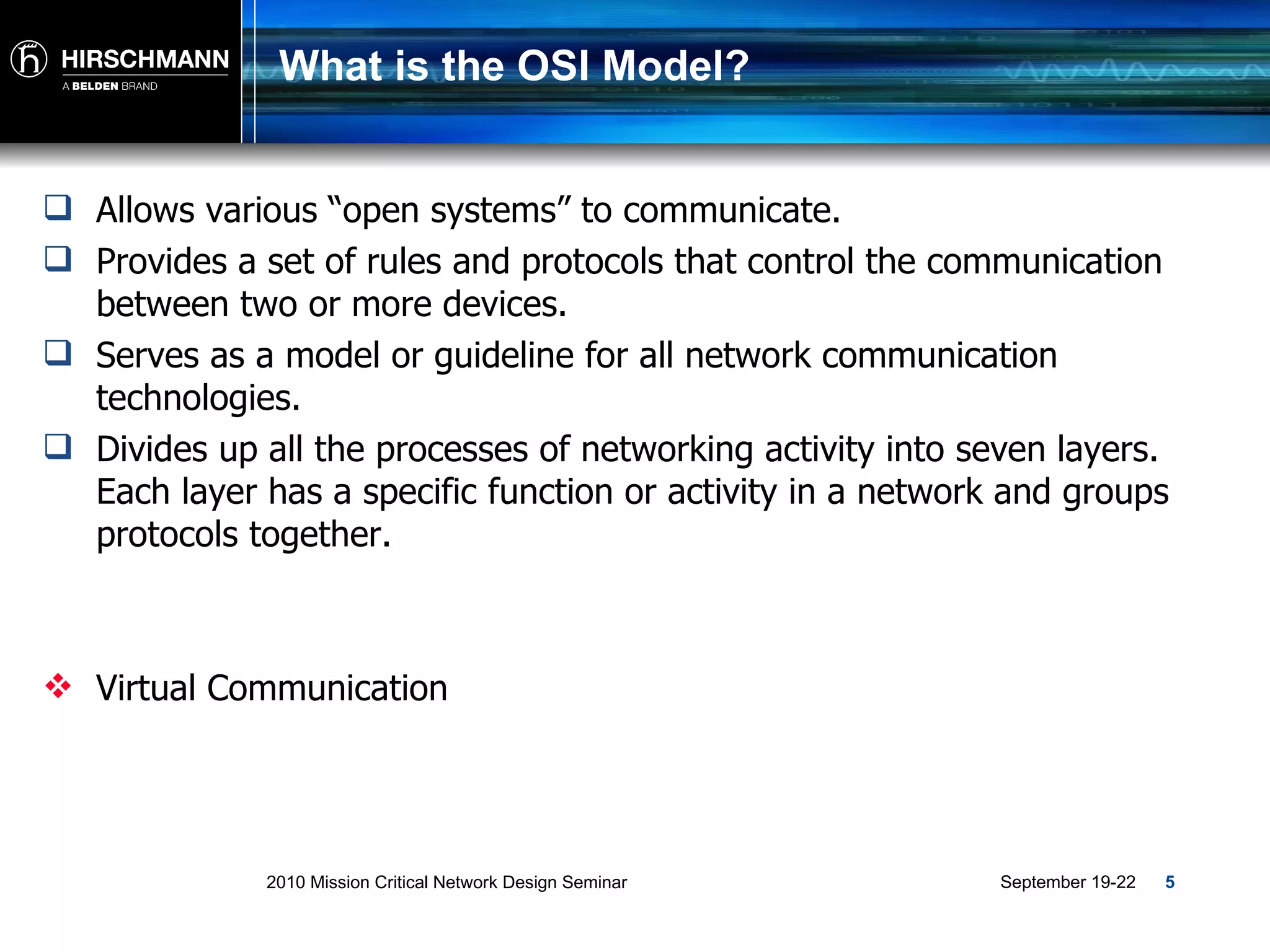
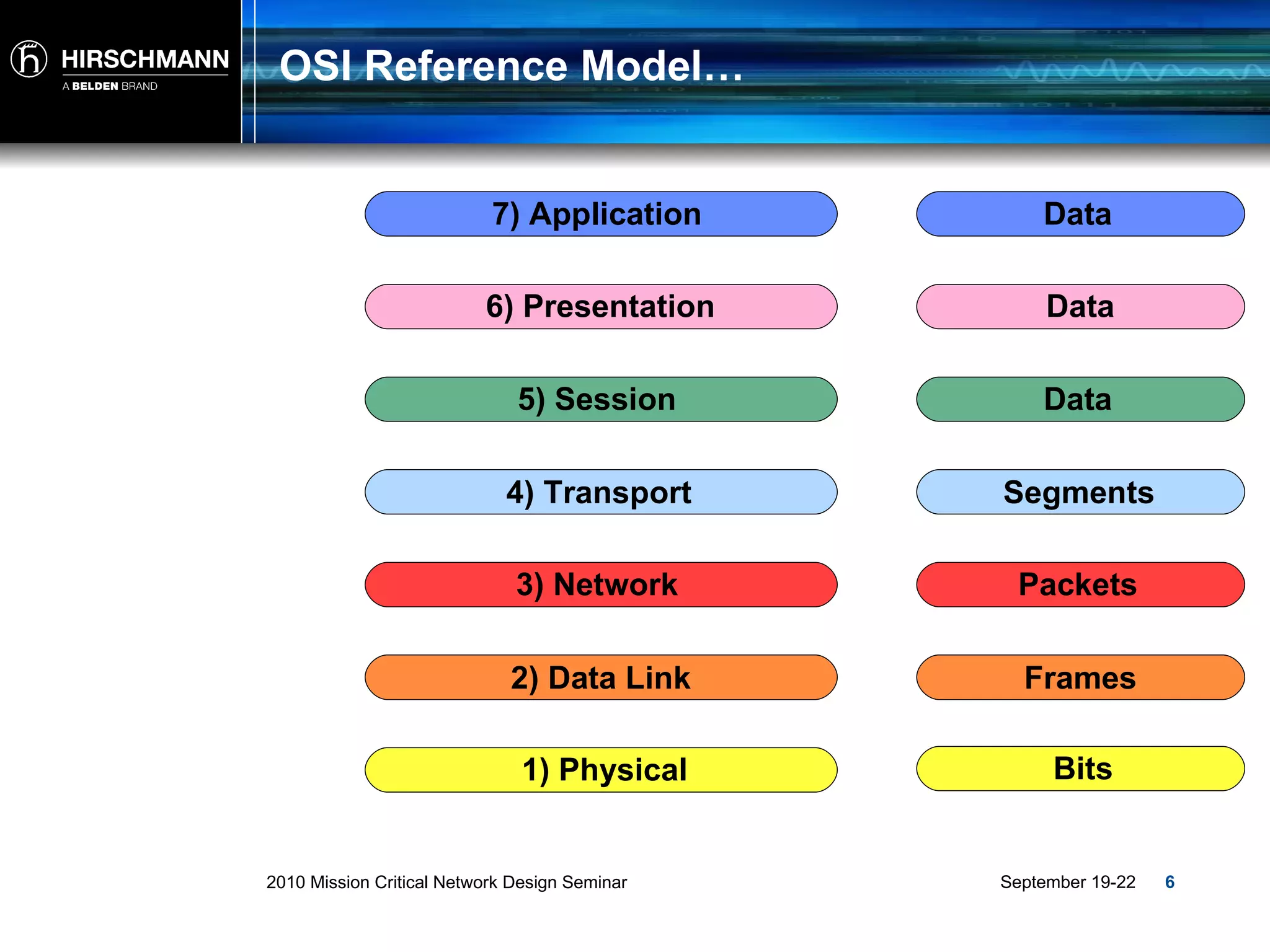
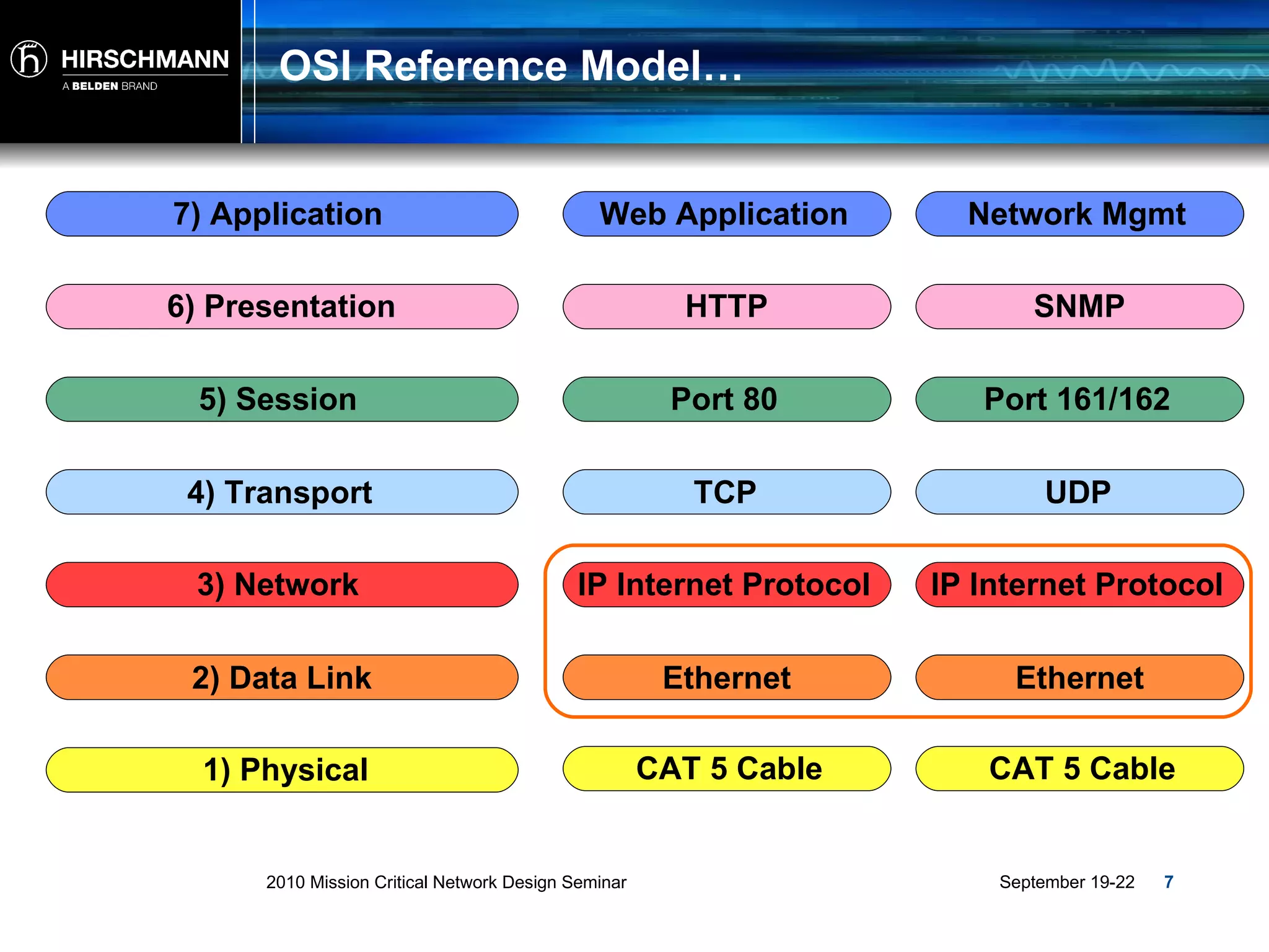
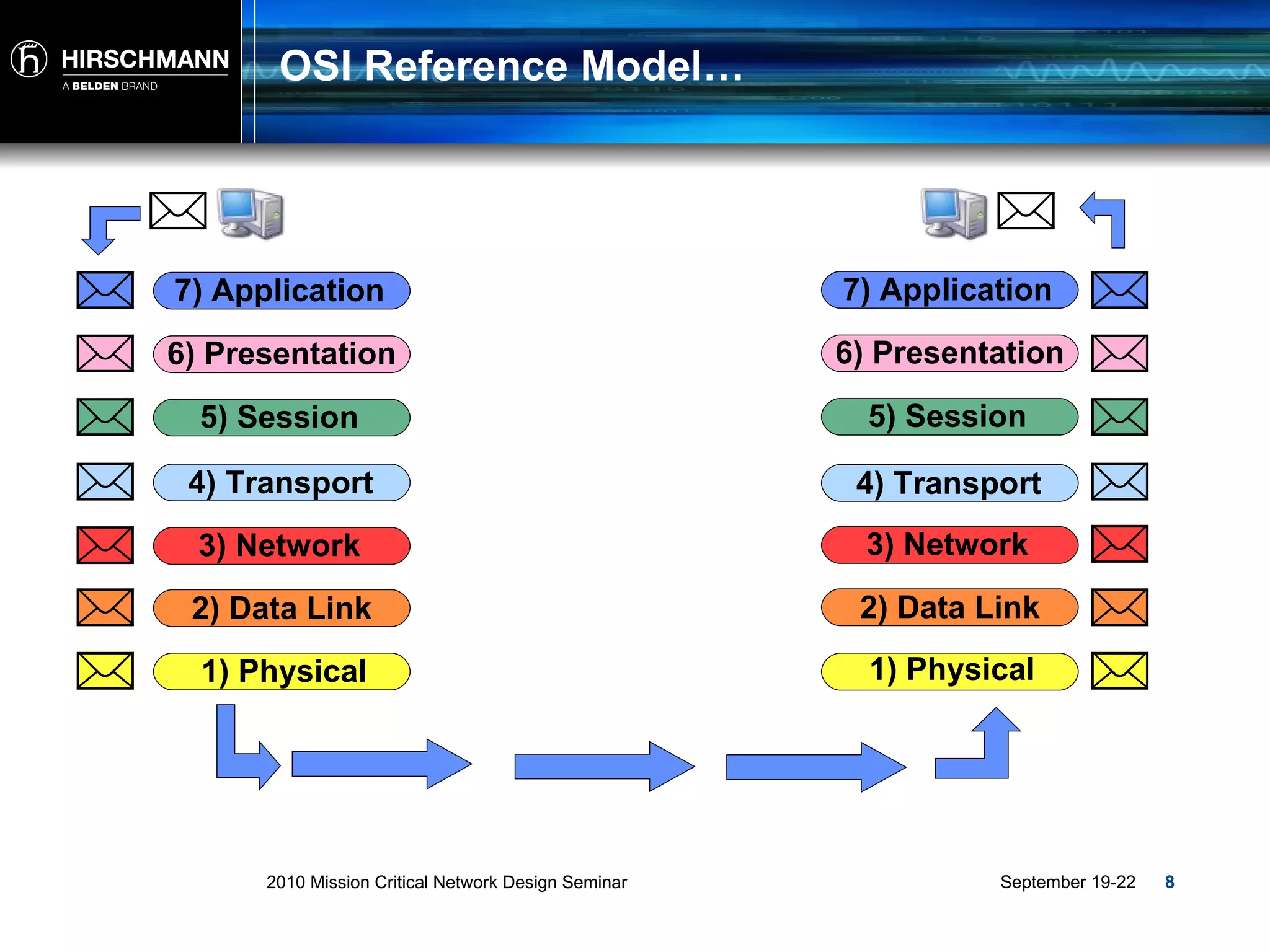
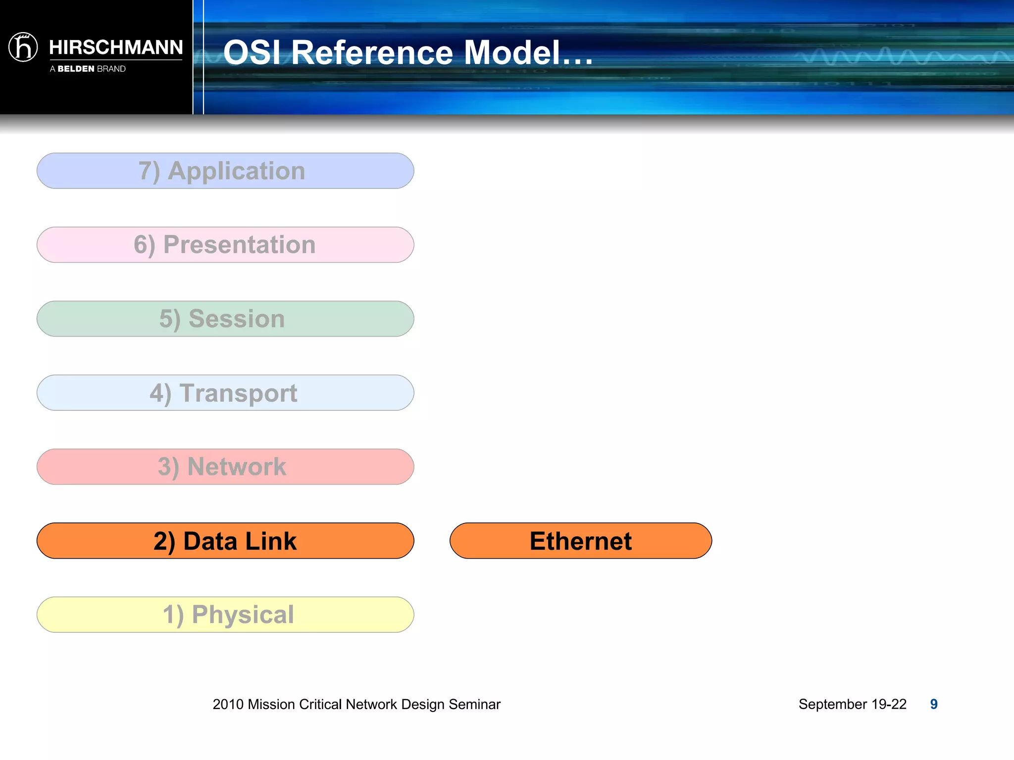
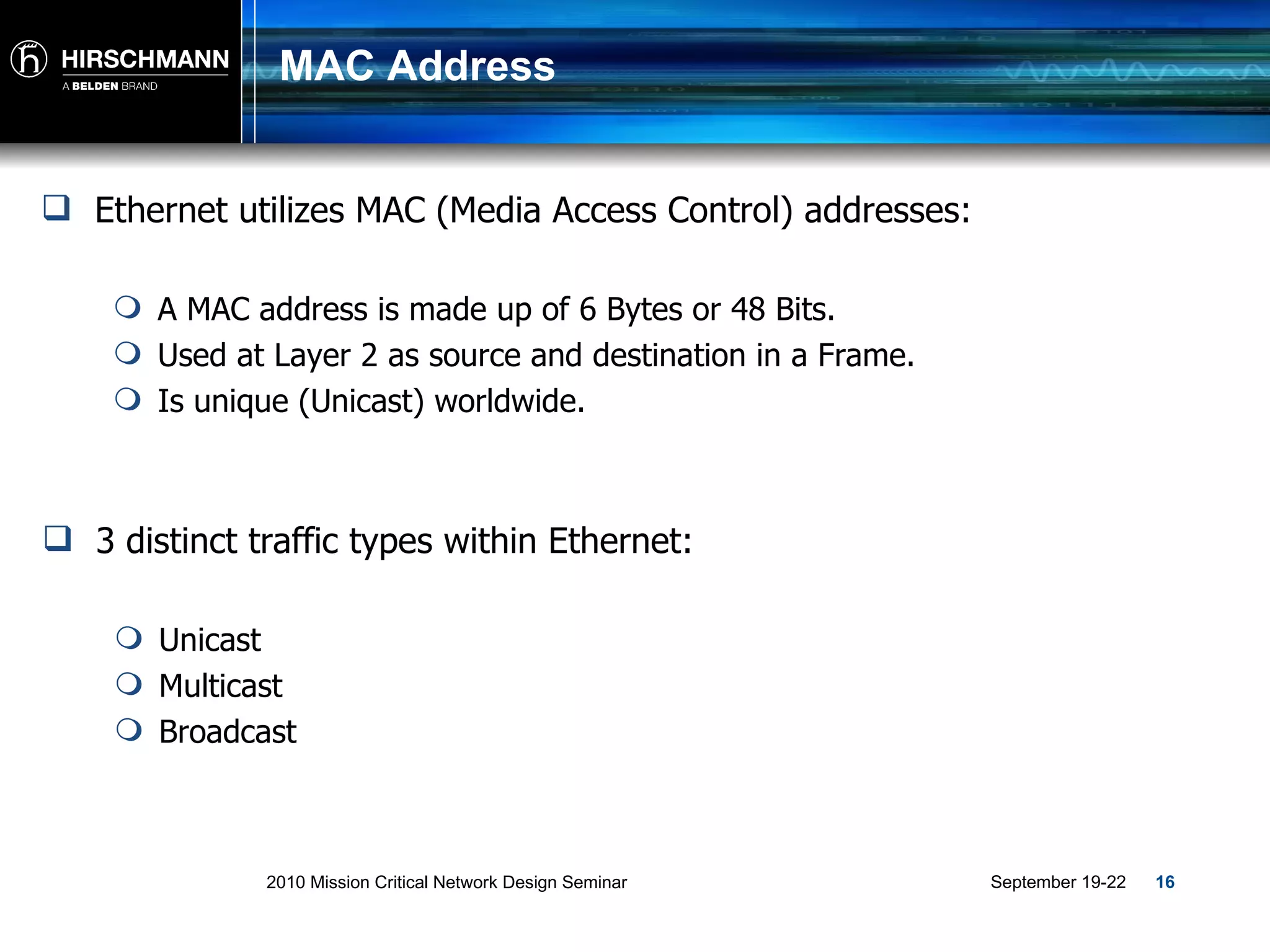
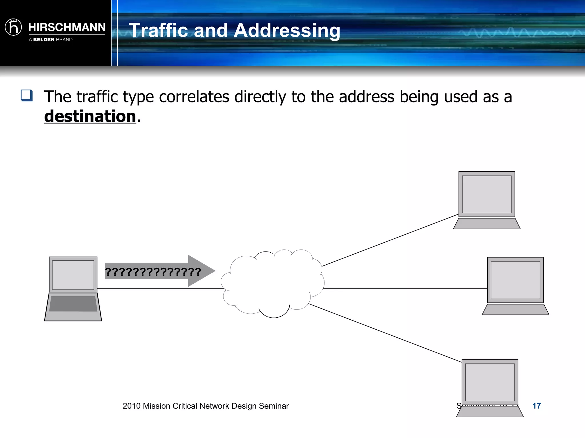
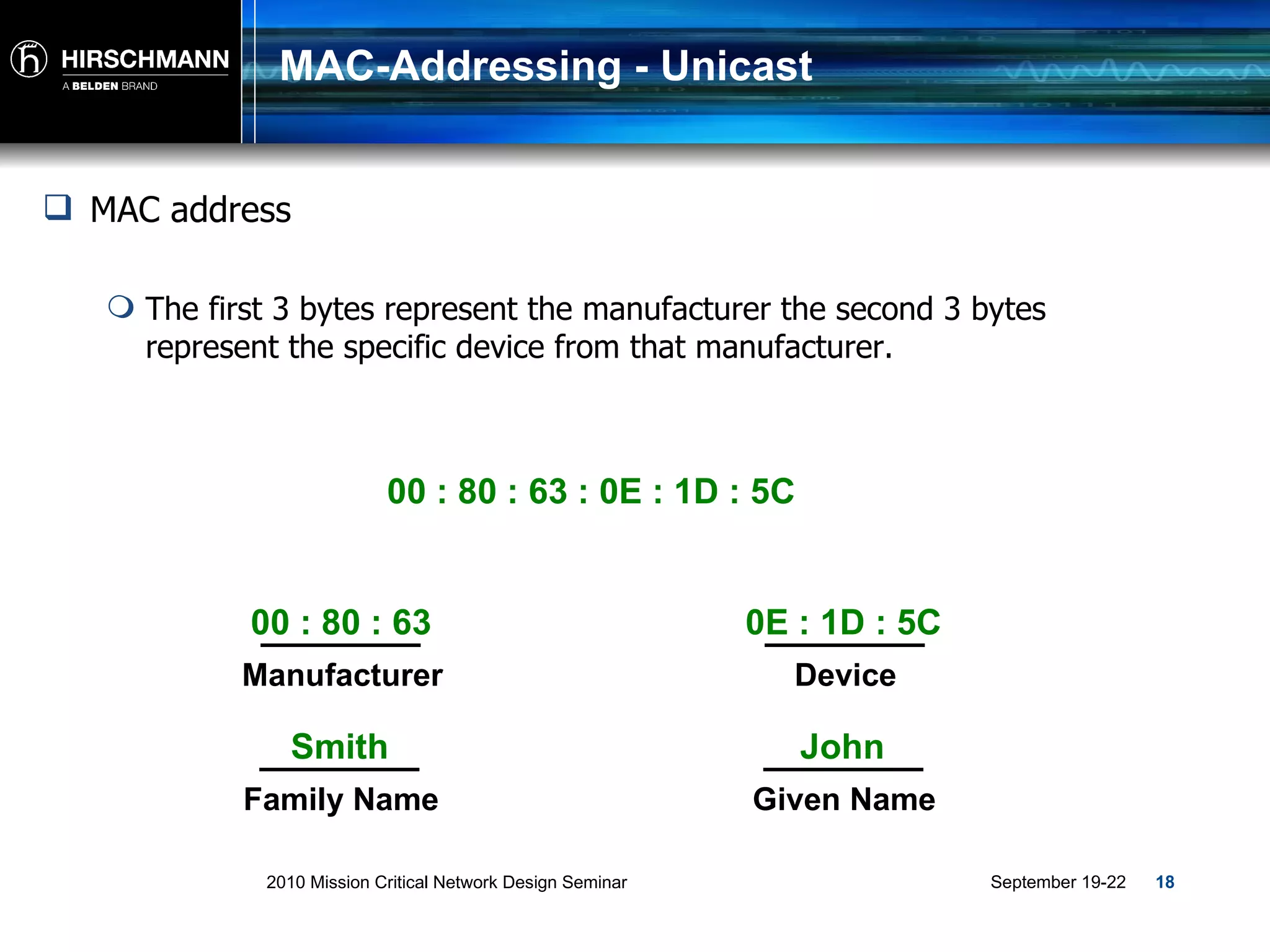
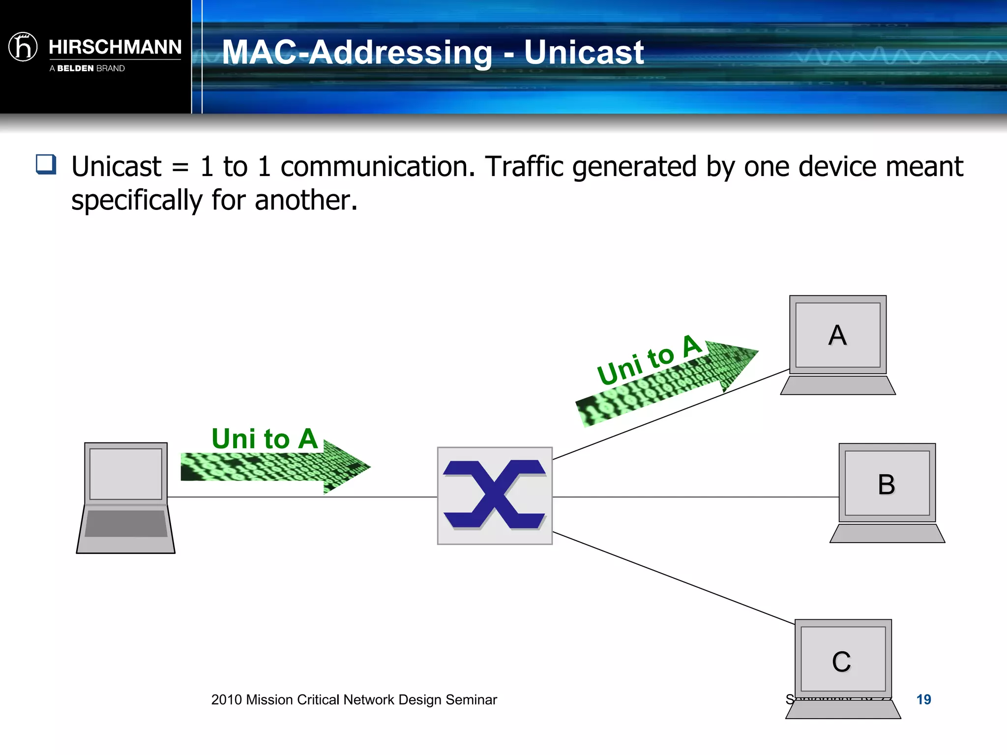
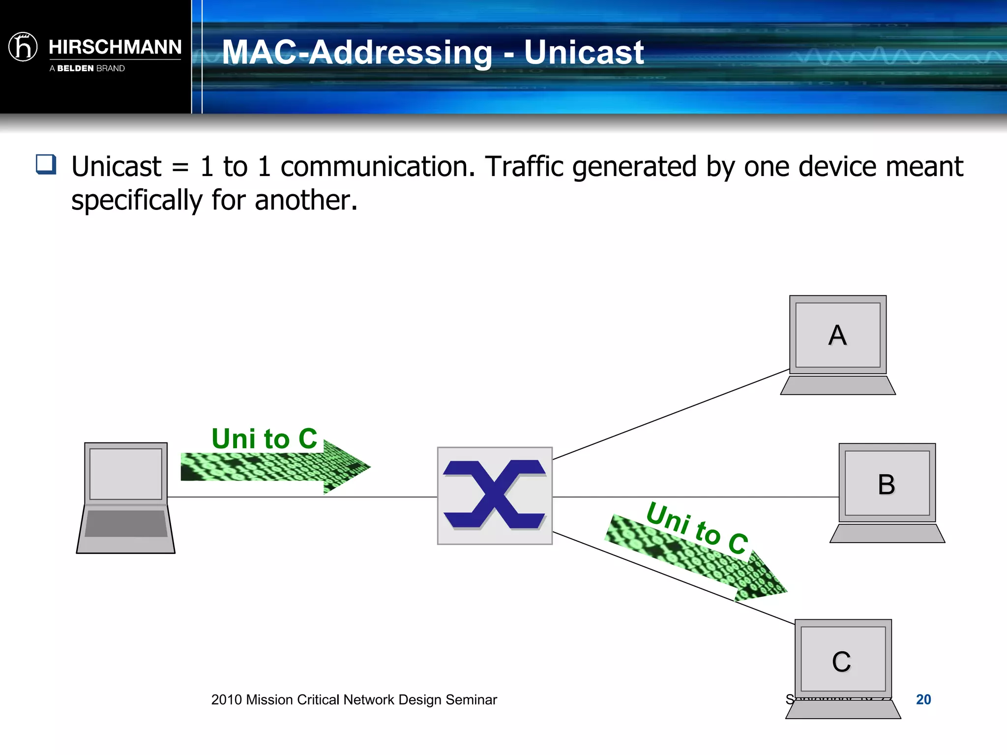
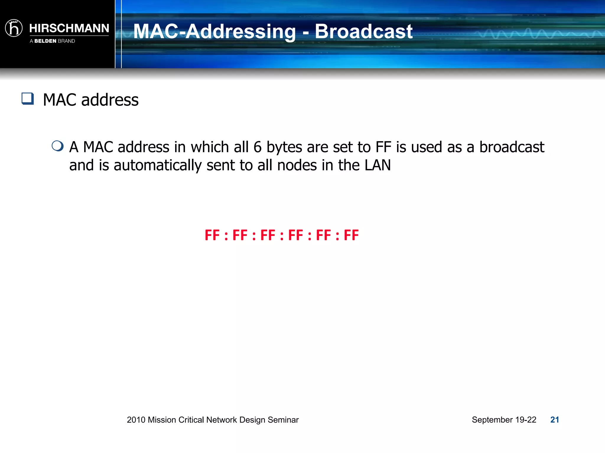
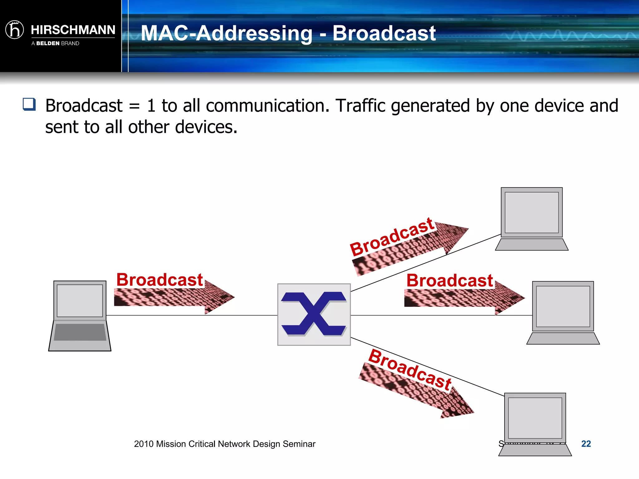
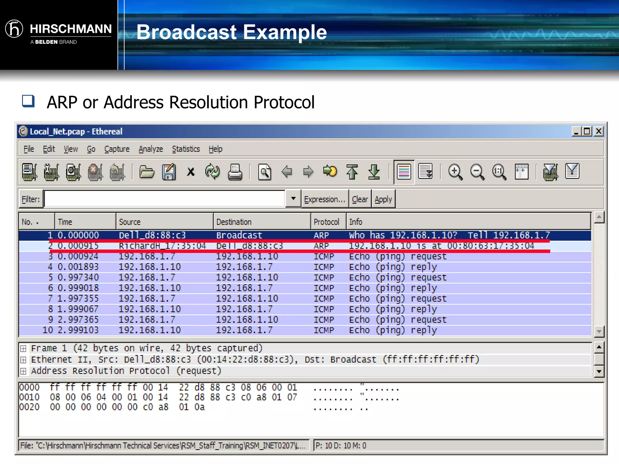
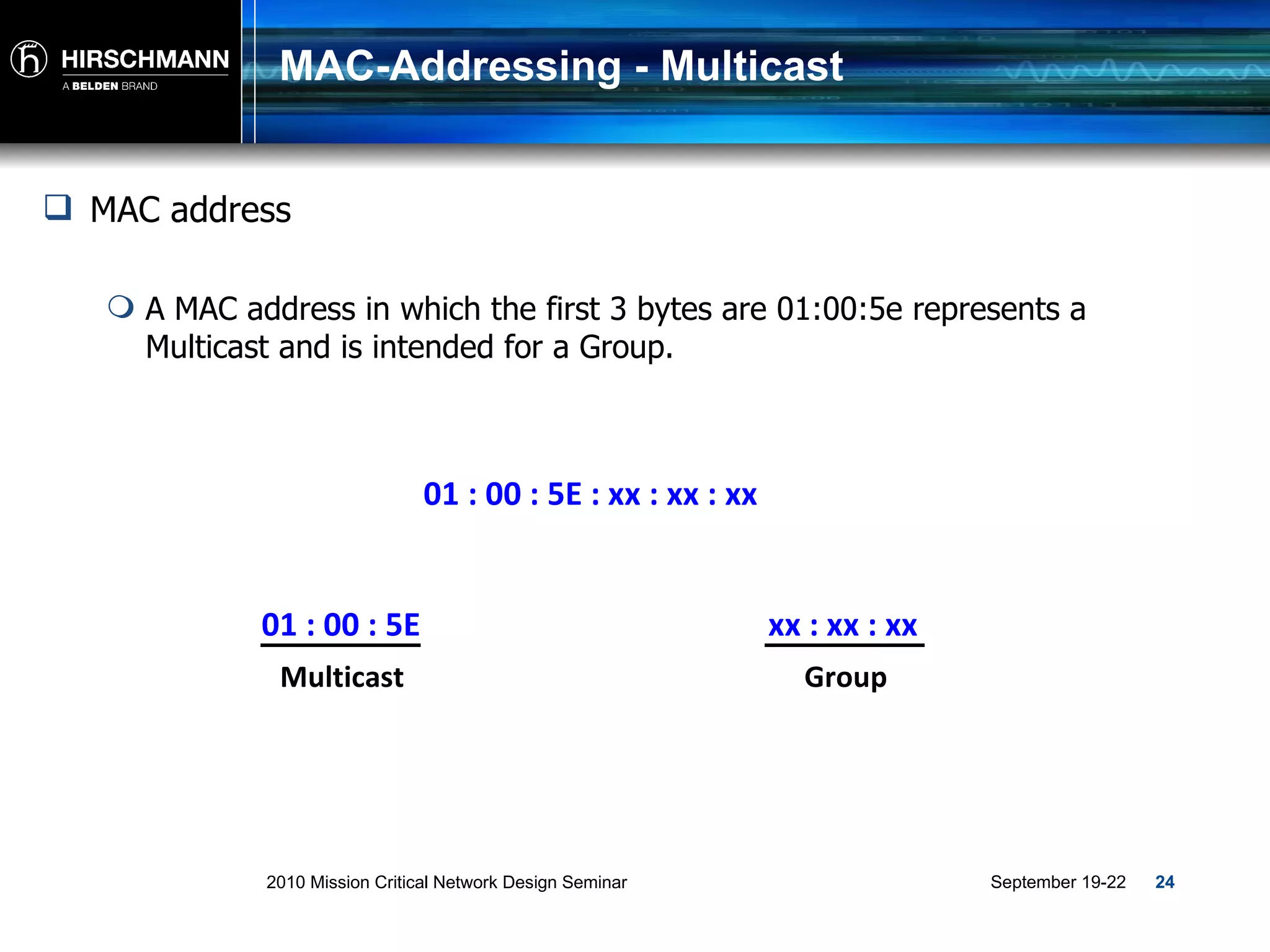
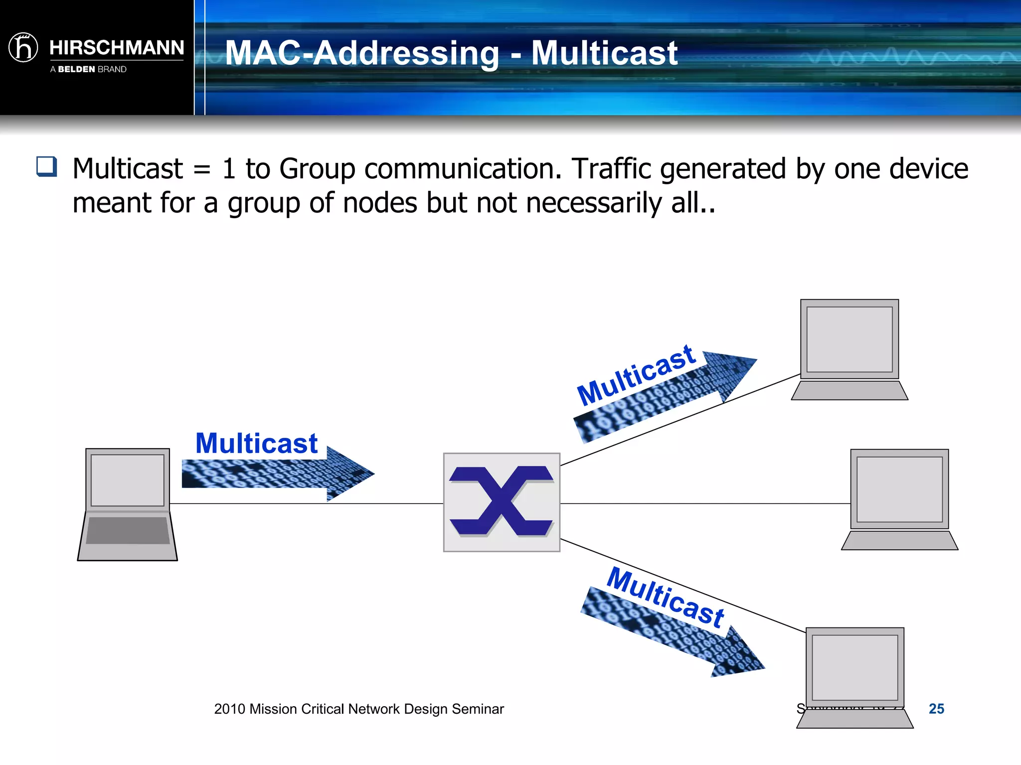
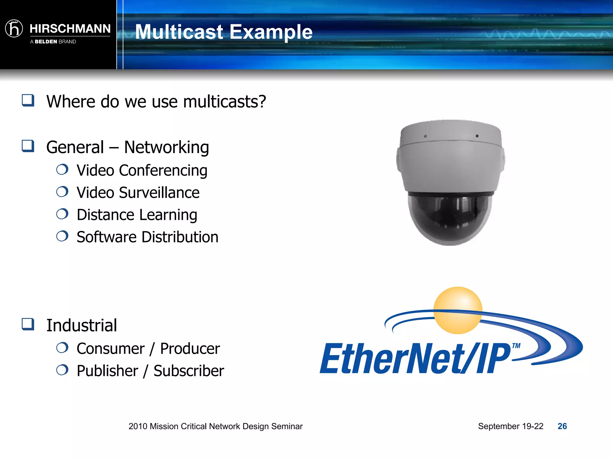
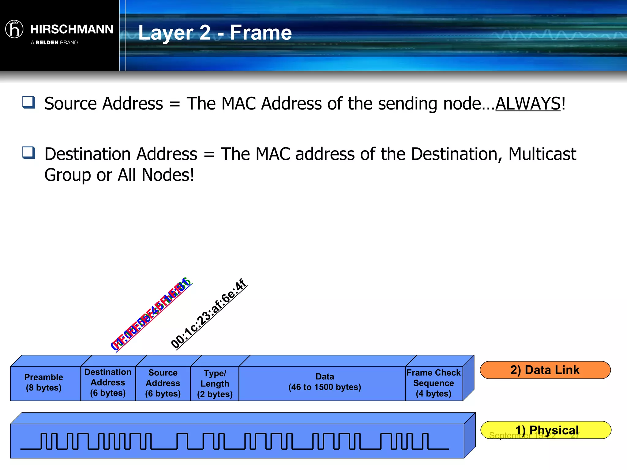
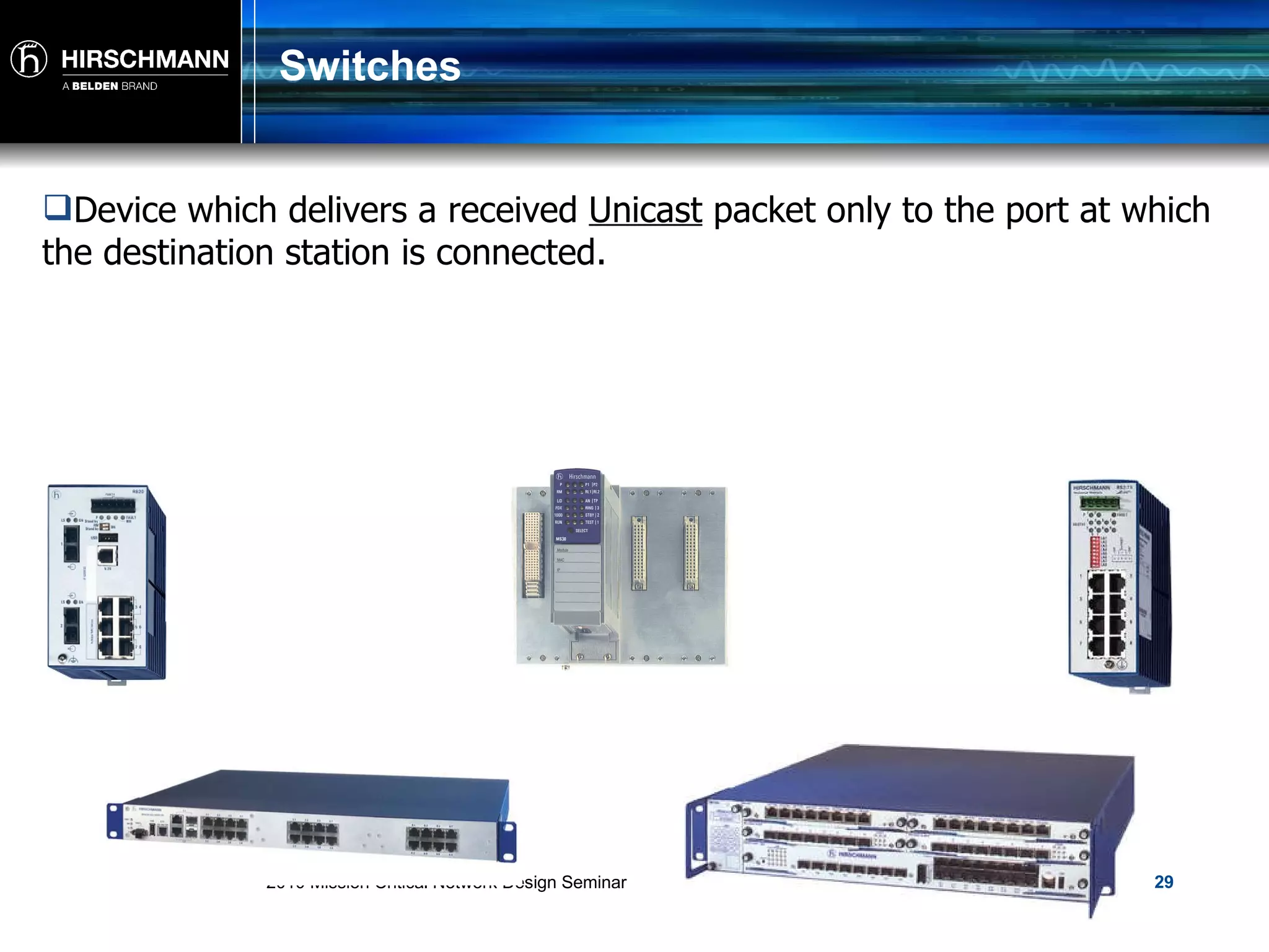
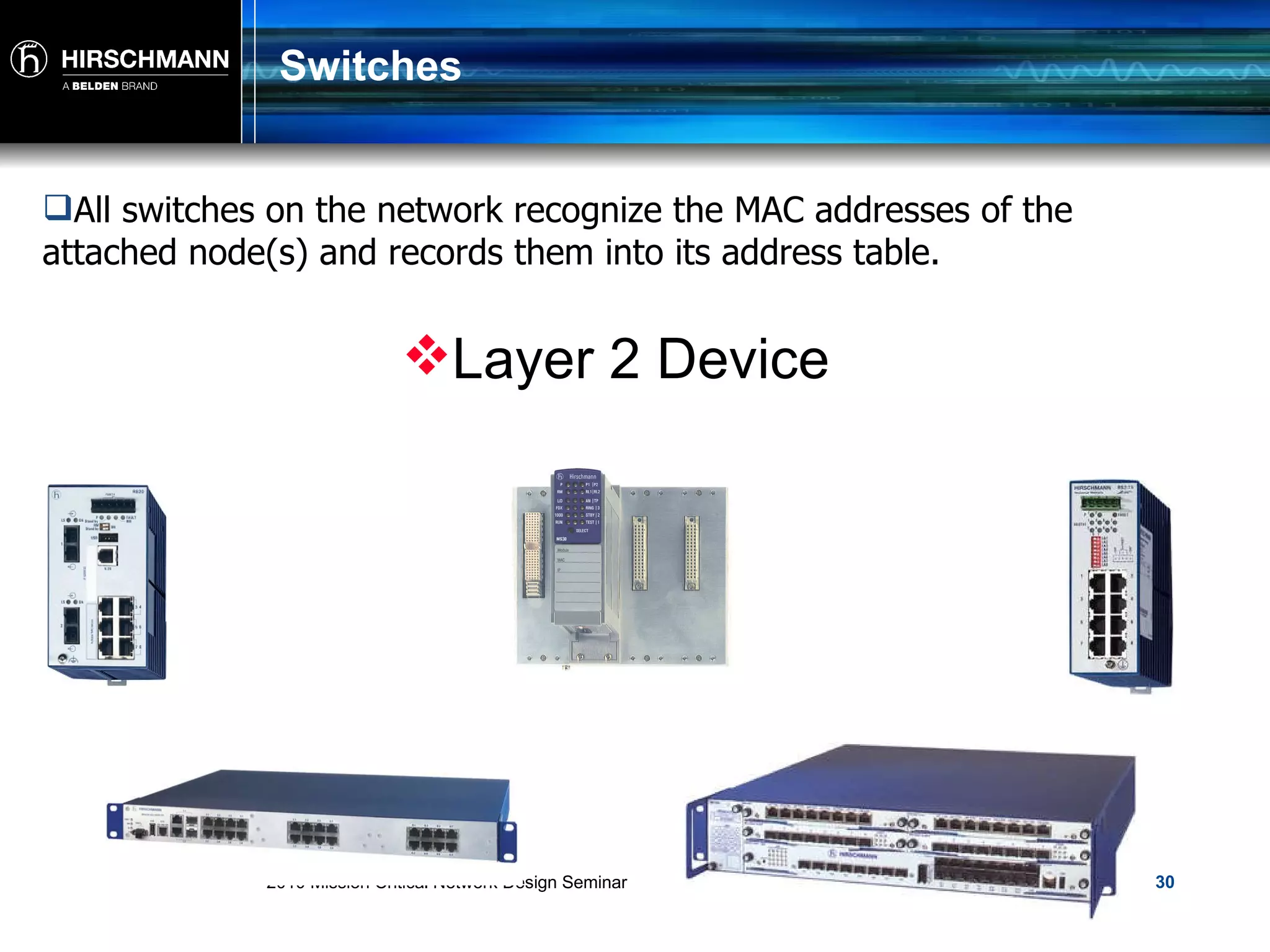
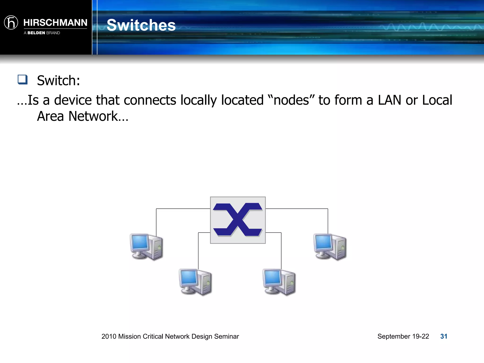
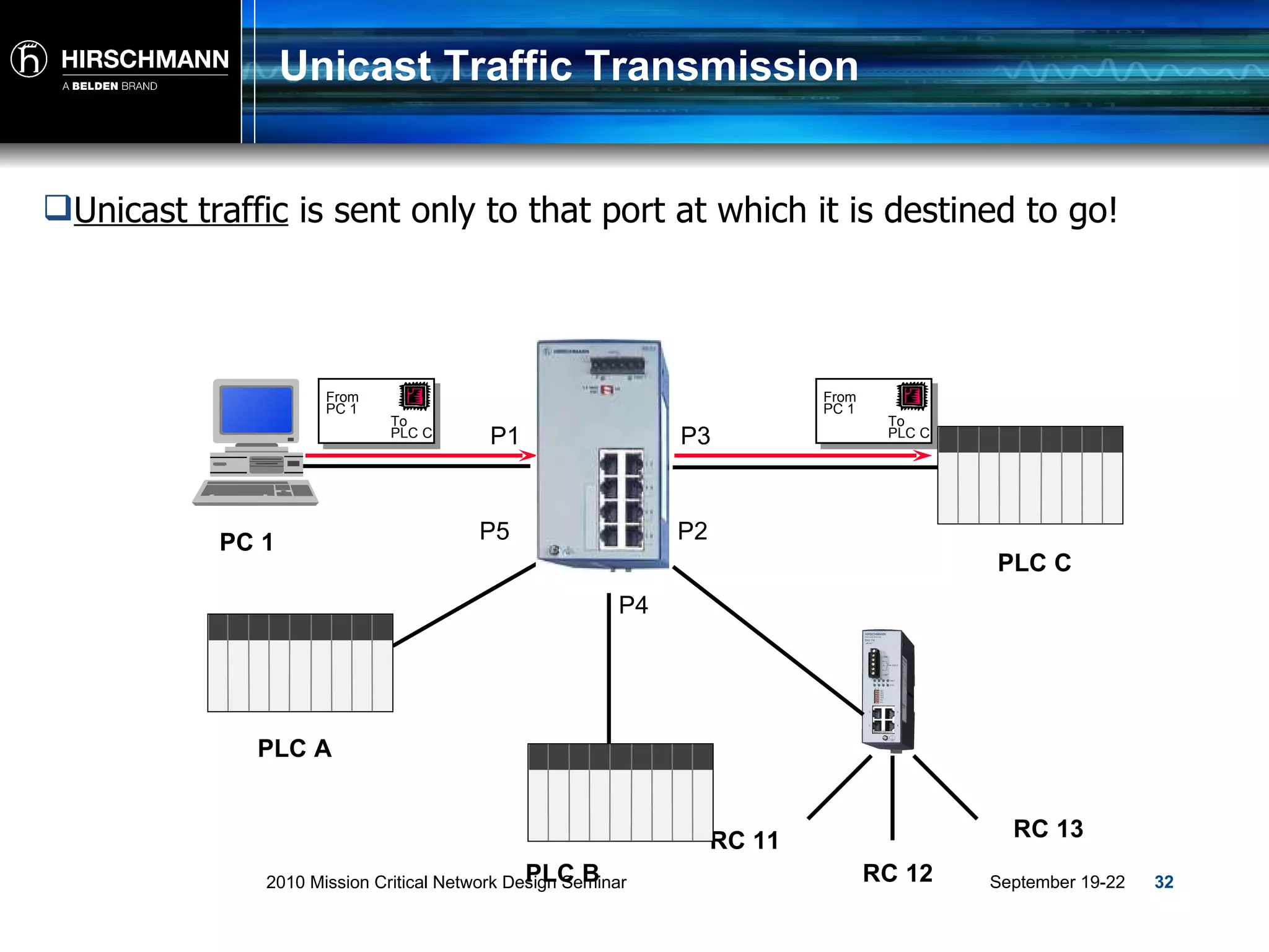
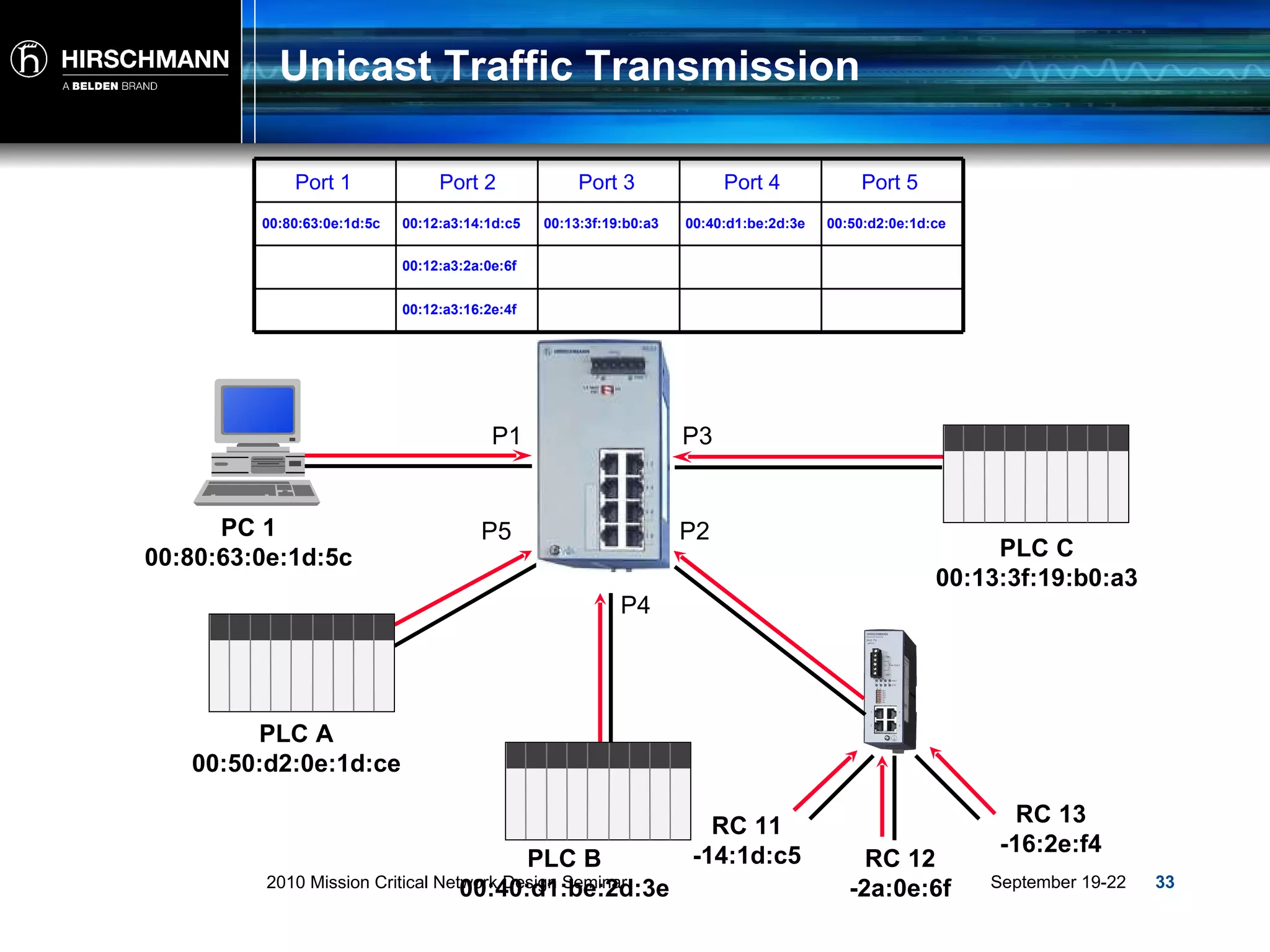
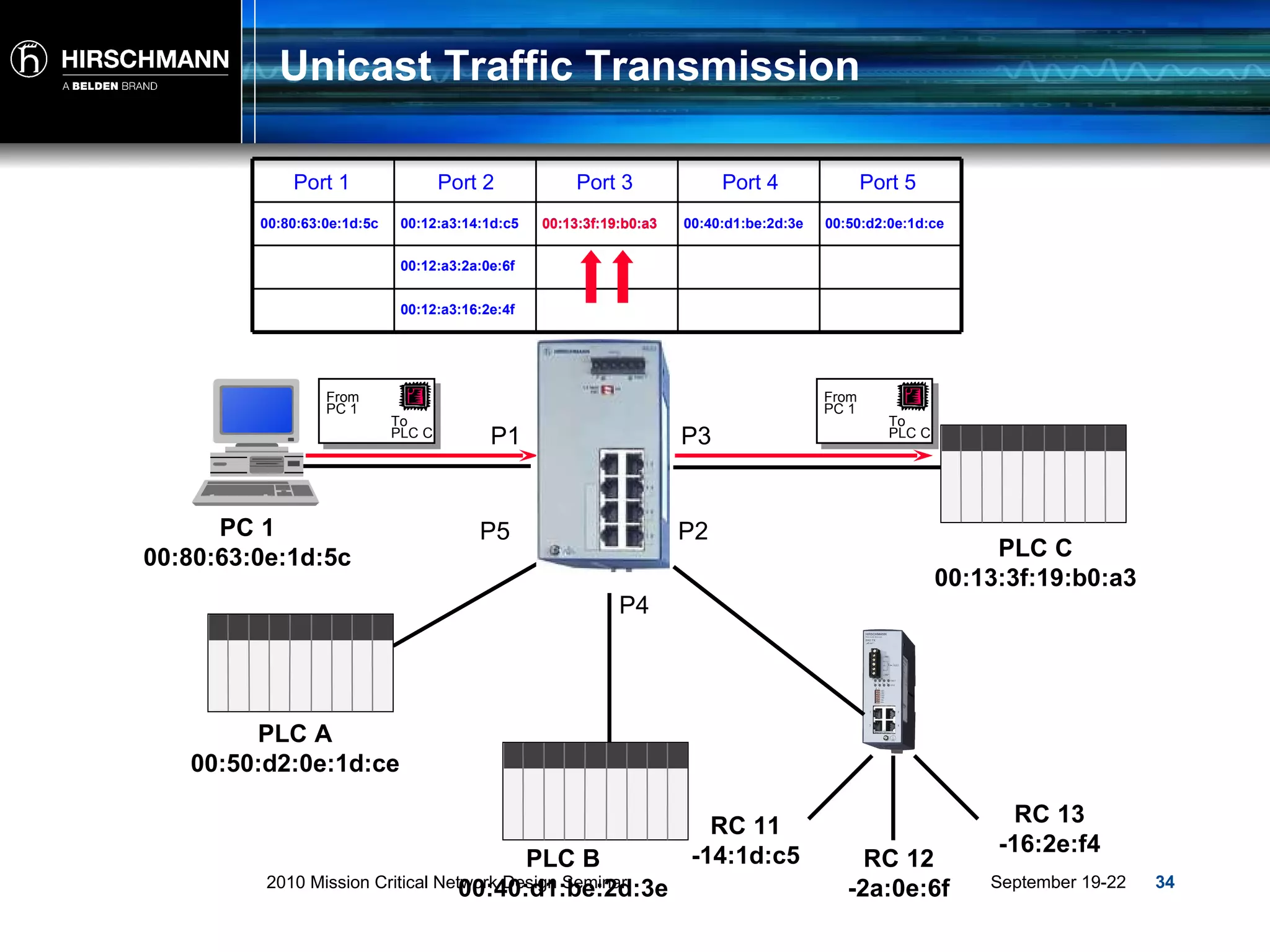
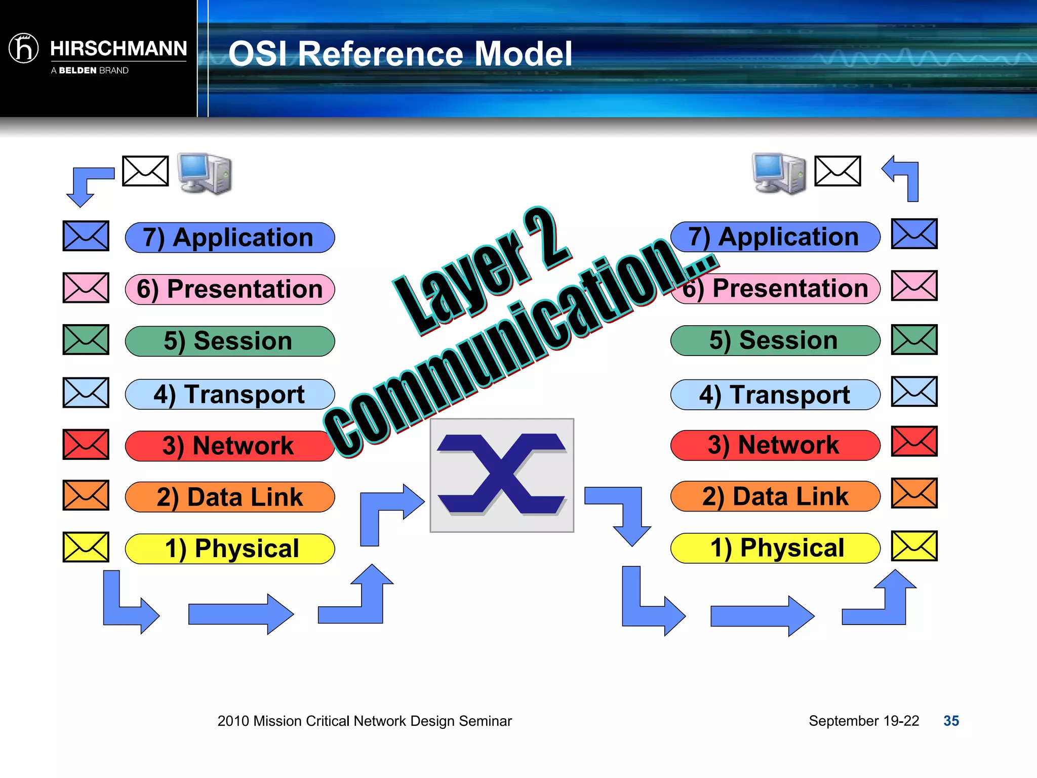
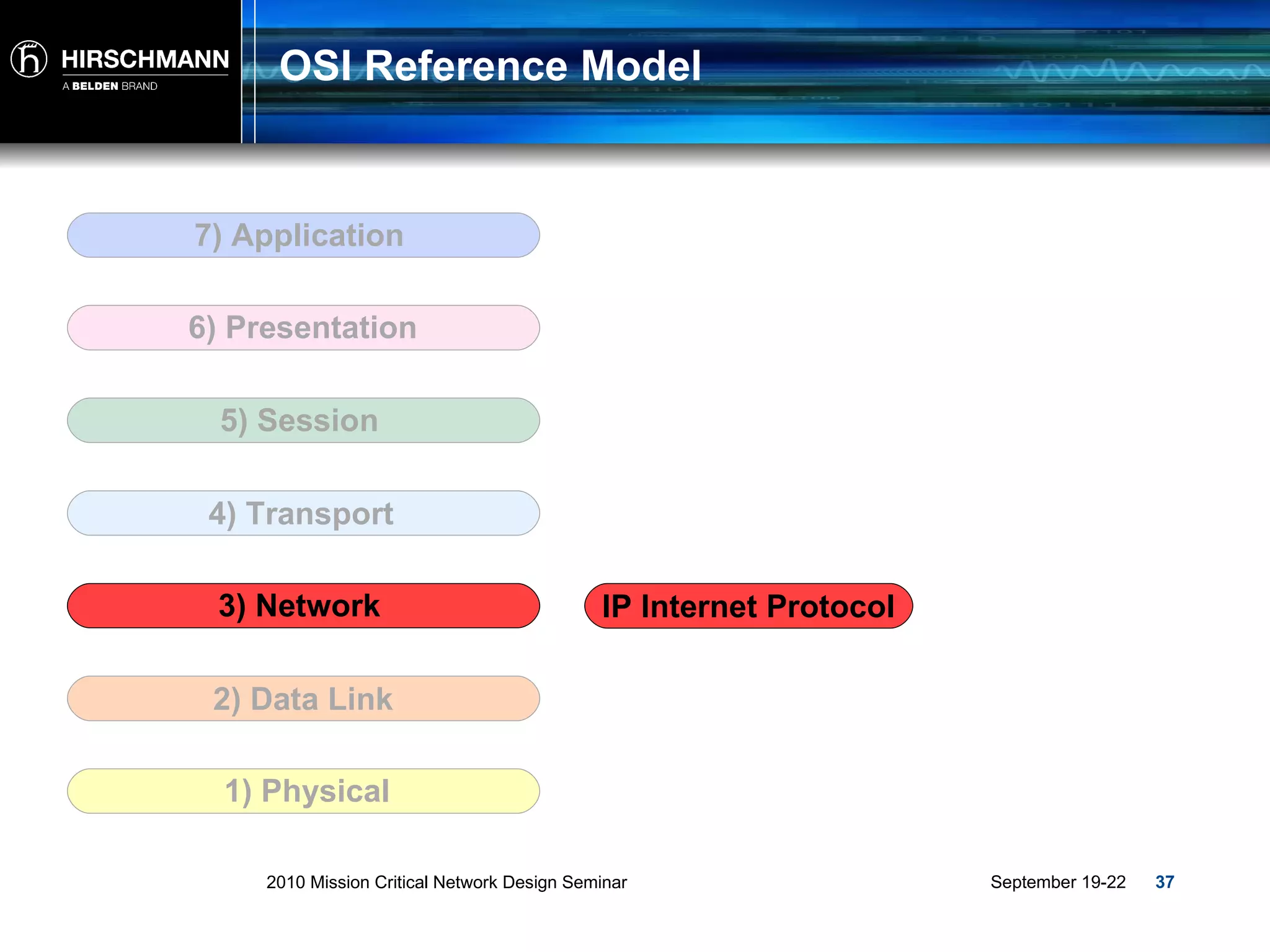
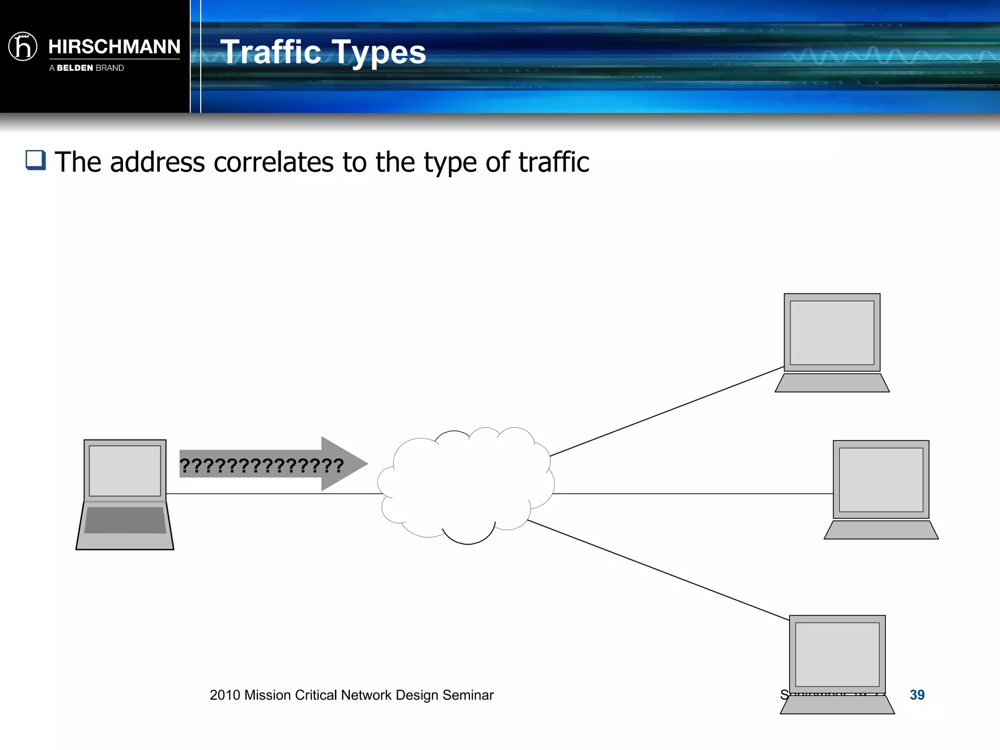
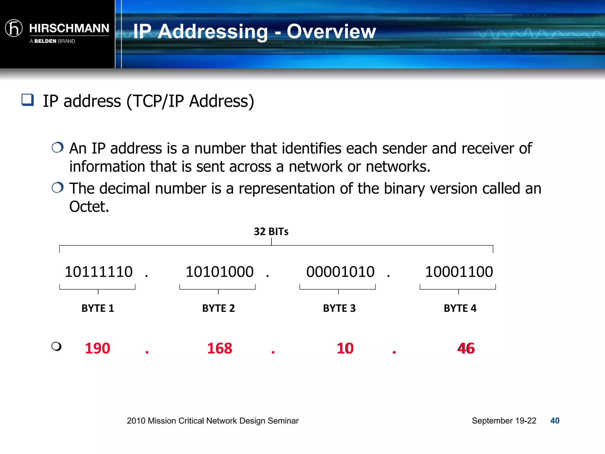
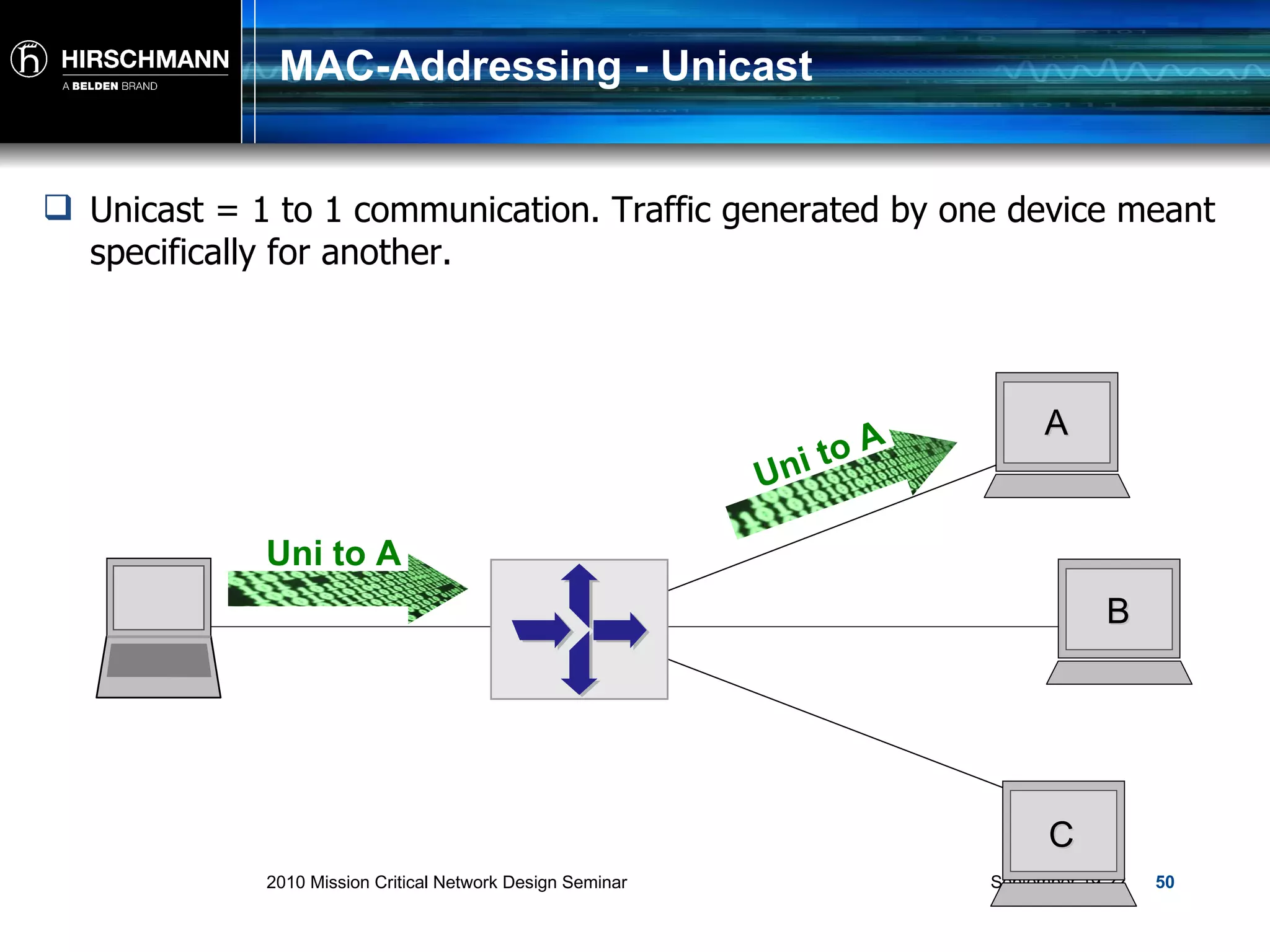
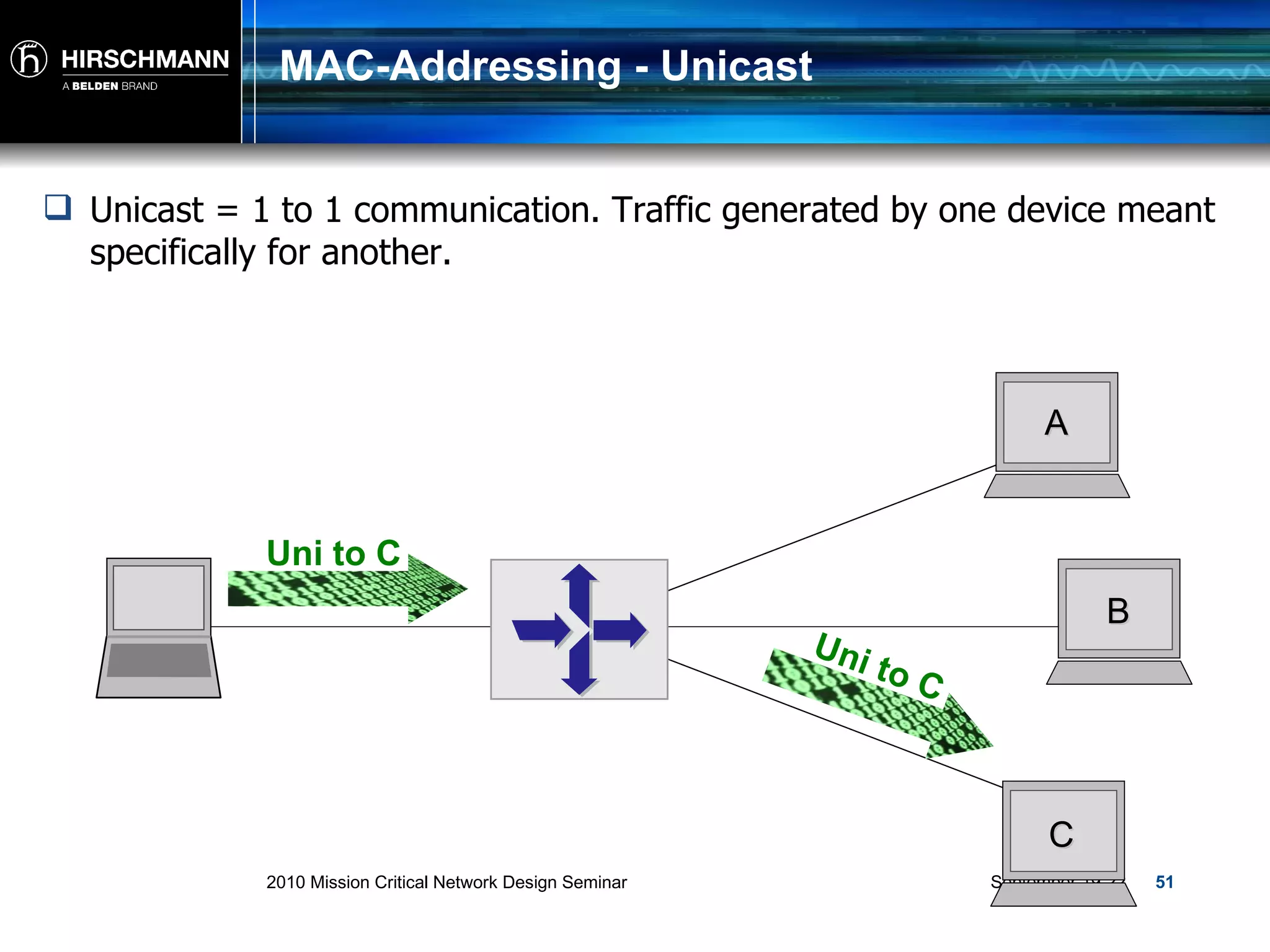
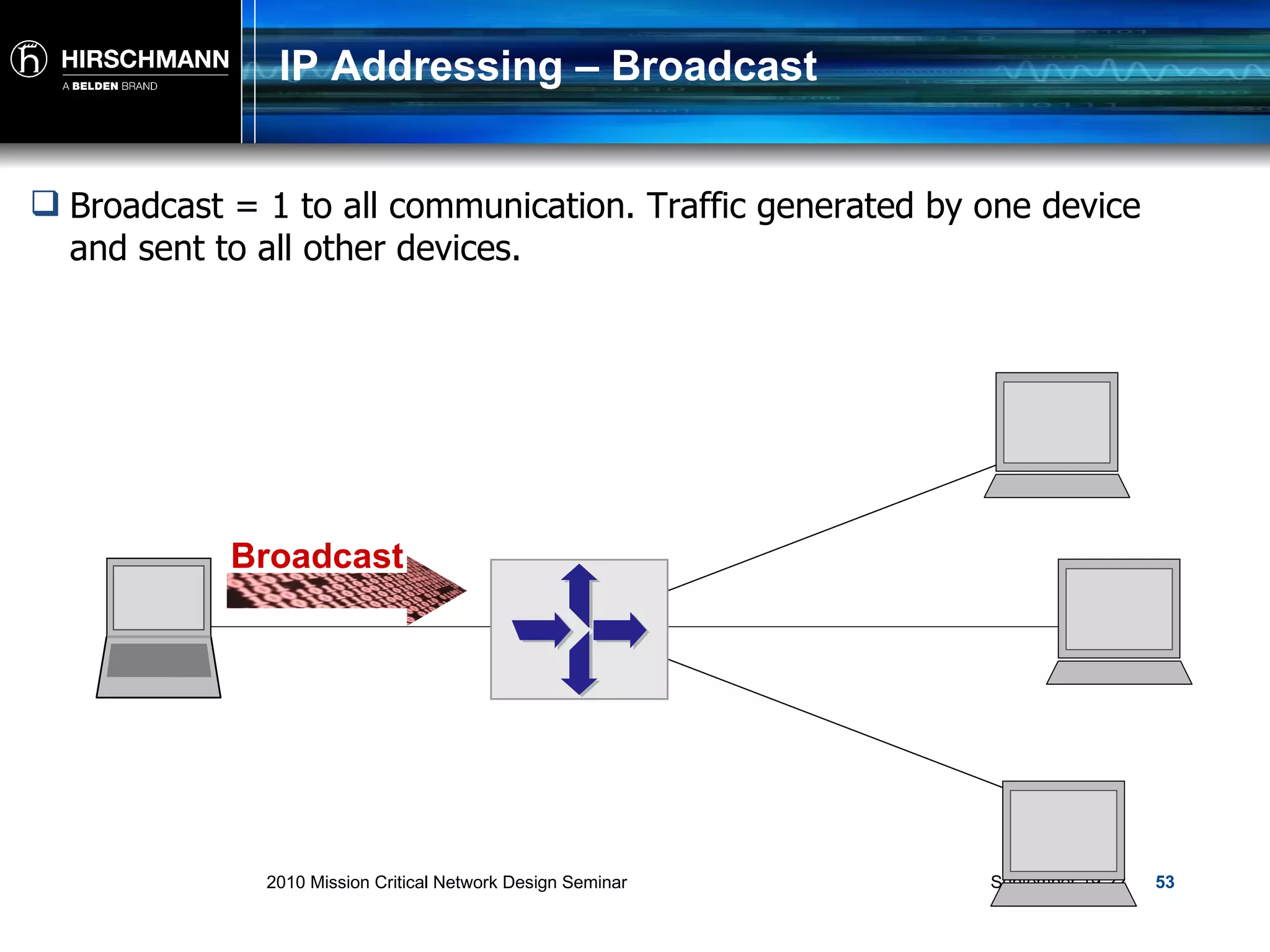
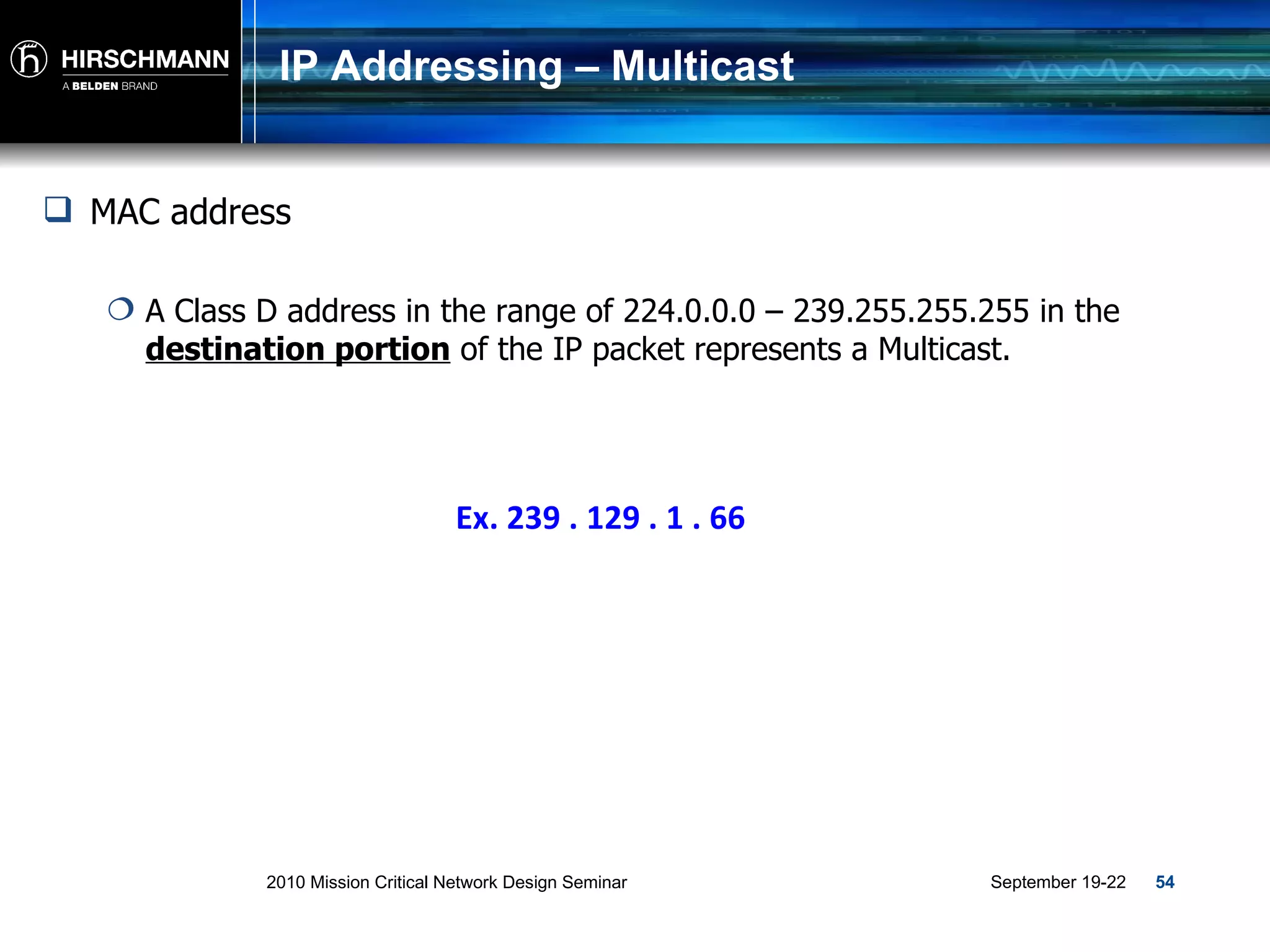
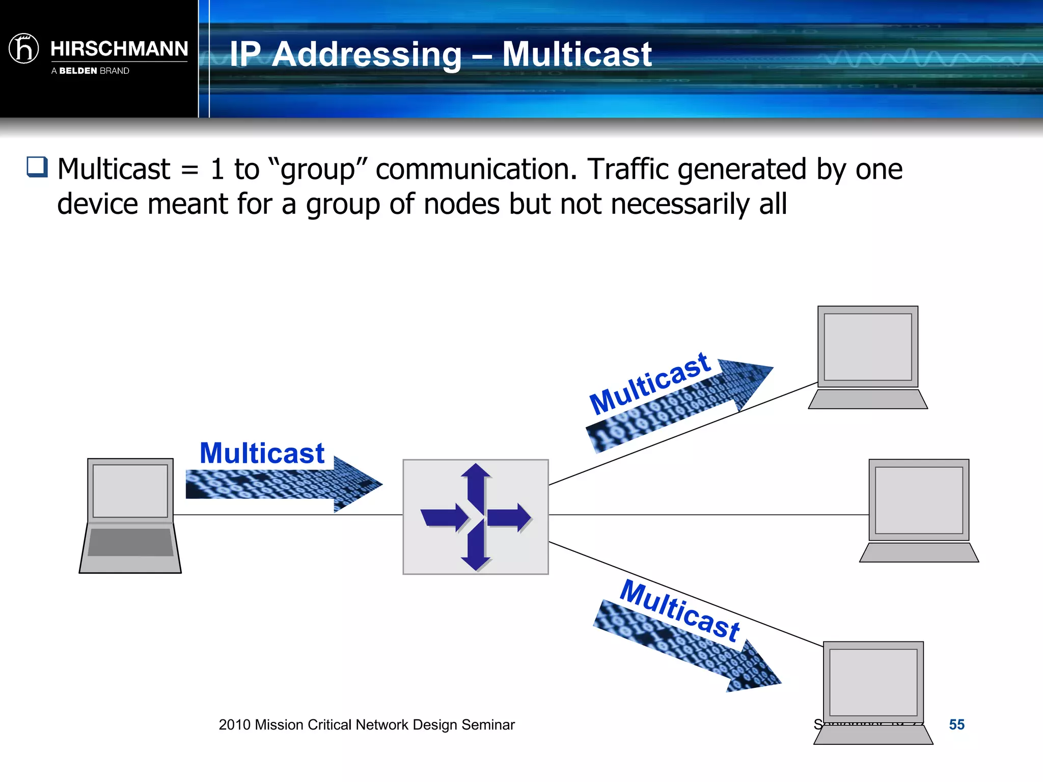
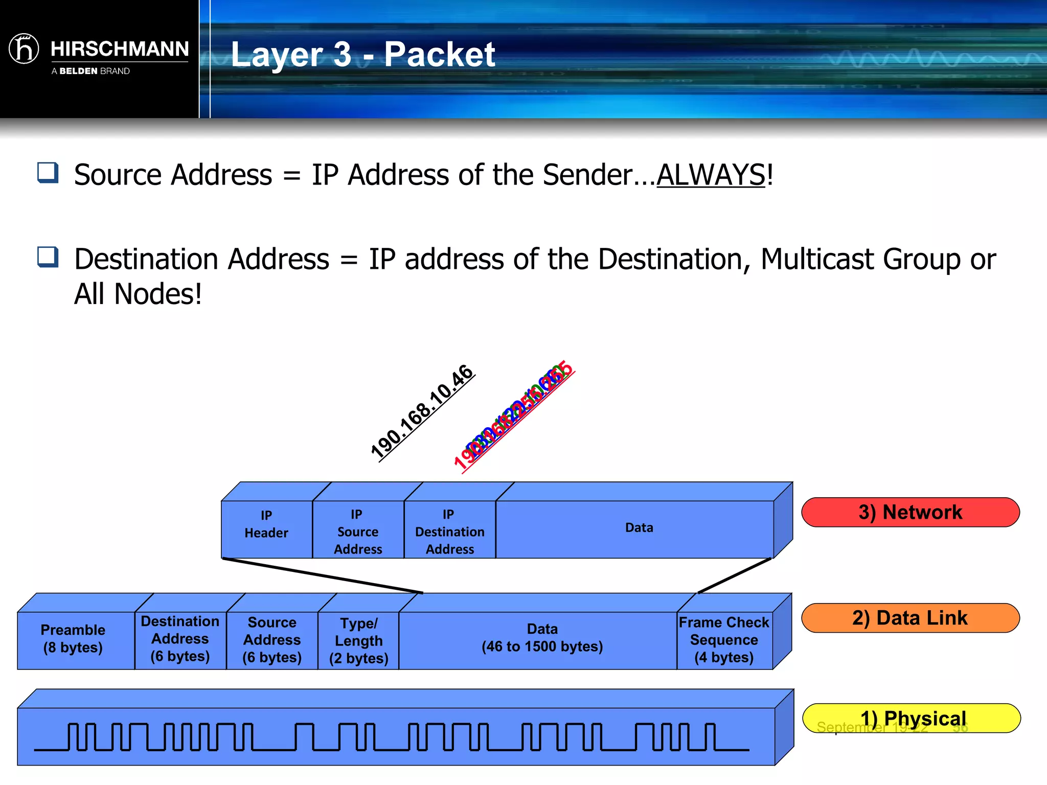
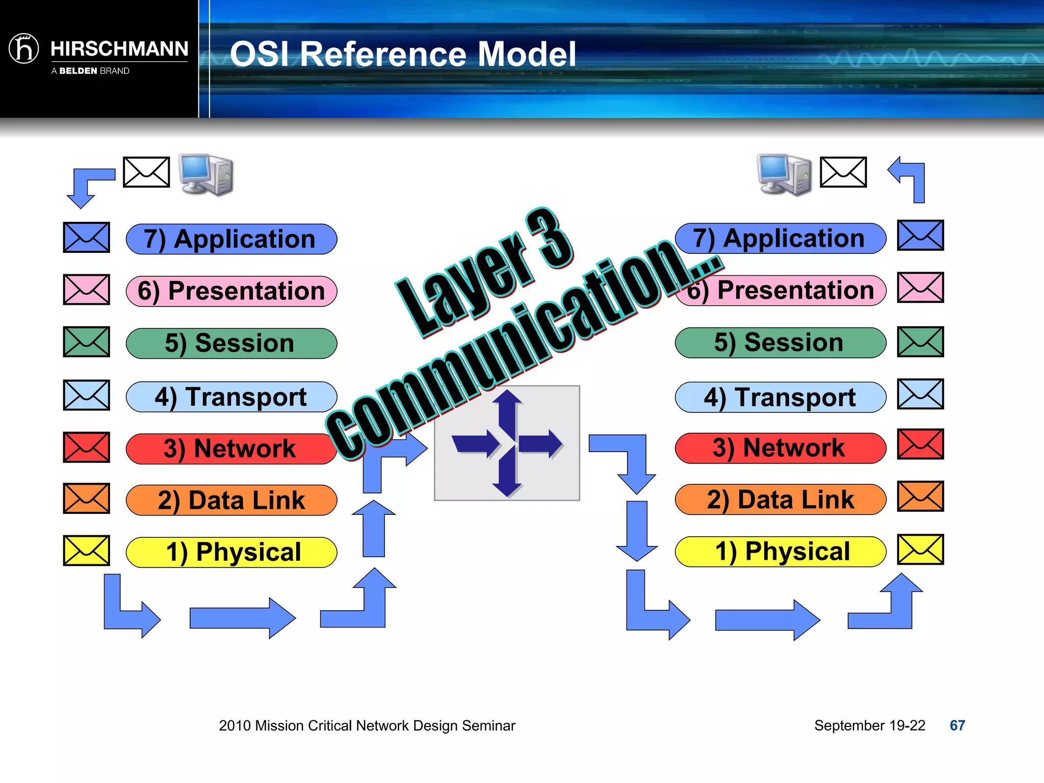
2010 Mission Critical Network Design Seminar TP01:Introduction to Ethernet Networking
Ethernet Fundamentals
What is Ethernet?
What is the OSI Model?
What is the OSI Model? Allows various “open systems” to communicate. Provides a set of rules and protocols that control the communication between two or more devices. Serves as a model or guideline for all network communication technologies. Divides up all the processes of networking activity into seven layers. Each layer has a specific function or activity in a network and groups protocols together. Virtual Communication
OSI Reference Model… 2) Data Link 3) Network 4) Transport 5) Session 6) Presentation 7) Application 1) Physical Frames Packets Segments Data Data Data Bits
OSI Reference Model… 2) Data Link 3) Network 4) Transport 5) Session 6) Presentation 7) Application 1) Physical Ethernet IP Internet Protocol TCP Port 80 HTTP Web Application CAT 5 Cable Ethernet IP Internet Protocol UDP Port 161/162 SNMP Network Mgmt CAT 5 Cable
OSI Reference Model… 1) Physical 1) Physical 2) Data Link 3) Network 4) Transport 5) Session 6) Presentation 7) Application 2) Data Link 3) Network 4) Transport 5) Session 6) Presentation 7) Application
OSI Reference Model… 2) Data Link 3) Network 4) Transport 5) Session 6) Presentation 7) Application 1) Physical Ethernet
What is Ethernet?
What is Ethernet? Ethernet is a standard (IEEE) communications method developed for the building up of LAN’s or Local Area Networks . LAN: Two or more computing devices linked together Network Interface in each device Cable or Radio to connect each device Infrastructure equipment (Switch, Router or Wireless AP) to send network traffic.
What is Ethernet? Simply put, Ethernet is a way of transmitting a signal between two or more devices… ? Server 1 Server 2
What is Ethernet? Ethernet is “Data Transport" and can be compared to a truck in a way. A truck is typically loaded at one location Carries its cargo to another location Then the cargo is unloaded and compared to the manifest Ethernet
What is Ethernet? The “transportation method” for Ethernet is called a frame! A Frame is typically loaded at one location (The source…) Carries its cargo (data) to another location (The destination…) Then the data is unloaded checked for validity Preamble (8 bytes) Destination Address (6 bytes) Source Address (6 bytes) Type/ Length (2 bytes) Data (46 to 1500 bytes) Frame Check Sequence (4 bytes)
Traffic and  Addressing
MAC Address Ethernet utilizes MAC (Media Access Control) addresses: A MAC address is made up of 6 Bytes or 48 Bits. Used at Layer 2 as source and destination in a Frame. Is unique (Unicast) worldwide. 3 distinct traffic types within Ethernet: Unicast Multicast Broadcast
Traffic and Addressing The traffic type correlates directly to the address being used as a  destination . ??????????????
MAC-Addressing - Unicast MAC address The first 3 bytes represent the manufacturer the second 3 bytes represent the specific device from that manufacturer.  00 : 80 : 63 : 0E : 1D : 5C 00 : 80 : 63 Manufacturer 0E : 1D : 5C Device Smith Family Name John Given Name
MAC-Addressing - Unicast Unicast = 1 to 1 communication. Traffic generated by one device meant specifically for another. A B C Uni to A Uni to A
MAC-Addressing - Unicast Unicast = 1 to 1 communication. Traffic generated by one device meant specifically for another. A B C Uni to C Uni to C
MAC-Addressing - Broadcast FF : FF : FF : FF : FF : FF MAC address A MAC address in which all 6 bytes are set to FF is used as a broadcast and is automatically sent to all nodes in the LAN
MAC-Addressing - Broadcast Broadcast = 1 to all communication. Traffic generated by one device and sent to all other devices. Broadcast Broadcast Broadcast Broadcast
Broadcast Example ARP or Address Resolution Protocol
MAC-Addressing - Multicast 01 : 00 : 5E : xx : xx : xx MAC address A MAC address in which the first 3 bytes are 01:00:5e represents a Multicast and is intended for a Group. 01 : 00 : 5E Multicast xx : xx : xx Group
MAC-Addressing - Multicast Multicast = 1 to Group communication. Traffic generated by one device meant for a group of nodes but not necessarily all.. Multicast Multicast Multicast
Multicast Example Where do we use multicasts? General – Networking Video Conferencing Video Surveillance Distance Learning Software Distribution Industrial Consumer / Producer Publisher / Subscriber
Layer 2 - Frame Source Address = The MAC Address of the sending node… ALWAYS ! Destination Address = The MAC address of the Destination, Multicast Group or All Nodes! 00:1c:23:af:6e:4f 00:1d:09:c5:ba:86 01:00:5e:40:10:01 FF:FF:FF:FF:FF Preamble (8 bytes) Destination Address (6 bytes) Source Address (6 bytes) Type/ Length (2 bytes) Data (46 to 1500 bytes) Frame Check Sequence (4 bytes) 1) Physical 2) Data Link
Switches
Switches Device which delivers a received  Unicast  packet only to the port at which the destination station is connected.
Switches All switches on the network recognize the MAC addresses of the attached node(s) and records them into its address table.  Layer 2 Device
Switches Switch:  … Is a device that connects locally located “nodes” to form a LAN or Local Area Network…
Unicast Traffic Transmission Unicast traffic  is sent only to that port at which it is destined to go! P1 P4 P3 P2 P5 PLC A PLC C PLC B RC 13 RC 12 RC 11 PC 1 To PLC C From  PC 1 To PLC C From  PC 1
Unicast Traffic Transmission PLC A 00:50:d2:0e:1d:ce PLC C 00:13:3f:19:b0:a3 PLC B 00:40:d1:be:2d:3e RC 13 -16:2e:f4 RC 12 -2a:0e:6f RC 11 -14:1d:c5 P1 P4 P3 P2 P5 PC 1 00:80:63:0e:1d:5c 00:80:63:0e:1d:5c 00:50:d2:0e:1d:ce 00:12:a3:2a:0e:6f 00:13:3f:19:b0:a3 00:12:a3:16:2e:4f Port 1 00:12:a3:14:1d:c5 00:40:d1:be:2d:3e Port 2 Port 3 Port 4 Port 5
Unicast Traffic Transmission P1 P4 P3 P2 P5 Port 1 Port 2 Port 3 Port 4 Port 5 PLC A 00:50:d2:0e:1d:ce PLC C 00:13:3f:19:b0:a3 PLC B 00:40:d1:be:2d:3e RC 13 -16:2e:f4 RC 12 -2a:0e:6f RC 11 -14:1d:c5 PC 1 00:80:63:0e:1d:5c 00:80:63:0e:1d:5c 00:50:d2:0e:1d:ce 00:12:a3:2a:0e:6f 00:13:3f:19:b0:a3 00:12:a3:16:2e:4f 00:12:a3:14:1d:c5 00:40:d1:be:2d:3e 00:13:3f:19:b0:a3 To PLC C From  PC 1 To PLC C From  PC 1
OSI Reference Model Layer 2 communication... 2) Data Link 3) Network 4) Transport 5) Session 6) Presentation 7) Application 1) Physical 2) Data Link 3) Network 4) Transport 5) Session 6) Presentation 7) Application 1) Physical
Layer 3 Technology
OSI Reference Model 2) Data Link 3) Network 4) Transport 5) Session 6) Presentation 7) Application 1) Physical IP Internet Protocol
Traffic and  Addressing
Traffic Types The address correlates to the type of traffic ??????????????
IP Addressing - Overview IP address (TCP/IP Address) An IP address is a number that identifies each sender and receiver of information that is sent across a network or networks. The decimal number is a representation of the binary version called an Octet. 190  .  168  .  10  .  46 190  .  168  .  10  .  46 10111110  . 10101000  . 00001010  . 10001100 BYTE 1 BYTE 2 BYTE 3 BYTE 4 32 BITs
IP Addressing - Overview IP address Part of the IP Address represents the Network portion and part of the IP Address represents the Host or “Node” portion.  Each “Class” or range contains its own Broadcast element. 190 . 168 . 10 . 46 190 . 168 Network 10 . 46 Node Elm Street 1665 House Number
IP Addressing - Overview IP address Part of the IP Address represents the Network portion and part of the IP Address represents the Host or “Node” portion.  190 . 168 . 10 . 46 How do we define the Network portion and node portion???  190 . 168 Network 10 . 46 Node
IP Addressing – Subnet Mask Subnet Mask  In “Class Oriented” addressing there are default or natural masks that accompany the IP address. The Mask Bits identify which “Octets” represent the Network portion and which Octets represent the Node portion. IP Address – 190 . 168 . 10 . 46 Subnet Mask – 255 . 255 . 0 . 0
IP Addressing - Classes Traditional or "Class Oriented" Addressing: Class A = 1.0.0.0 to 126.255.255.255 Class B = 128.0.0.0 to 191.255.255.255 Class C = 192.0.0.0 to 223.255.255.255 Class D = 224.0.0.0 to 239.255.255.255 Class E = 240.0.0.0 to 255.255.255.255 Used for multicast applications only For experimental purposes Used for network Host/Node addressing
IP Addressing – Subnet Mask Class A = 255.0.0.0 (8 bit mask) Class B = 255.255.0.0 (16 bit mask) Class C = 255.255.255.0 (24 bit mask) Class Oriented addressing – Default or "natural masks": 11111111 .00000000.00000000.00000000 11111111.11111111 .00000000.00000000 11111111.11111111.11111111 .00000000
IP Addressing – Subnet Mask The "Mask" helps identify which portion of the IP address is the network portion and which is the Node portion. The network portion is identified by all "1"s The node portion is identified by all "0"s IP Address: 190.168.10.46 =  10111110.10101000.00001010.00101110 Subnet Mask: 255.255.0.0  =  Network Portion **What else does this tell me??? 11111111.11111111. 00000000.00000000
IP Addressing – Class B Network ID Per the specification: 1 st  and 2 nd  Octets are the "Network ID" This Class B Network (190.168.0.0) gives us two Octets of Node ID 256 * 256 = 65,536 possible addresses Minus 2 = 65,534 usable addresses. Why do subtract 2? 3 rd  and 4 th  Octets are the "Node ID's" Net ID: 190.168.0.0 How many node addresses do we have?
IP Addressing – Class B Broadcast Always subtract 2 from the number of Node ID's Node ID's cannot be all "0"s (Reserved for Network ID) Node ID's cannot be all "1"s (Reserved for Broadcast) The first address in this range: 10111110.10101000. 00000000 . 00000000 190.168. 0 . 0  (Network ID, not to be used) The last address in this range: 10111110.10101000. 11111111 . 11111111 190.168. 255 . 255  (Broadcast ID, not to be used)
IP Addressing – Unicast IP address A Class A, B or C address in the destination field of the IP Packet stipulates a Unicast. Ex. 190 . 168 . 10 . 46
MAC-Addressing - Unicast Unicast = 1 to 1 communication. Traffic generated by one device meant specifically for another. A B C Uni to A Uni to A
MAC-Addressing - Unicast Unicast = 1 to 1 communication. Traffic generated by one device meant specifically for another. A B C Uni to C Uni to C
IP Addressing – Broadcast Ex. 190 . 168 . 255 . 255 IP address Depending on the “Class”, an IP address with the Node portion set to all “1’s” stipulates a Broadcast and is sent to all nodes on the LAN. BROADCAST!!!
IP Addressing – Broadcast Broadcast = 1 to all communication. Traffic generated by one device and sent to all other devices. Broadcast
IP Addressing – Multicast Ex. 239 . 129 . 1 . 66 MAC address A Class D address in the range of 224.0.0.0 – 239.255.255.255 in the  destination portion  of the IP packet represents a Multicast.
IP Addressing – Multicast Multicast = 1 to “group” communication. Traffic generated by one device meant for a group of nodes but not necessarily all Multicast Multicast Multicast
Layer 3 - Packet Source Address = IP Address of the Sender… ALWAYS ! Destination Address = IP address of the Destination, Multicast Group or All Nodes! 190.168.10.46 190.168.10.50 239.129.1.66 190.168.255.255 Preamble (8 bytes) Destination Address (6 bytes) Source Address (6 bytes) Type/ Length (2 bytes) Data (46 to 1500 bytes) Frame Check Sequence (4 bytes) 1) Physical 2) Data Link IP Header IP  Source Address IP  Destination Address Data 3) Network
Mac/IP Relationship Last/Family Name Smith  First/Given Name  John  Street  Elm  House Number  1665 MAC Manufacturers Portion 00:80:63  = MAC Device Portion  00:1d:5c = IP Network Portion  190.168 = IP Host/Node Portion 10.46  =
Routers
Routers Device which interconnects different physical segments or LAN’s via Routes.
Routers Routers either learn dynamically or are told statically where different LAN’s reside and facilitate the transmission of data “Packets” among the networks. Layer 3 Device
Routers Router:  … Is a device that connects LAN’s (Subnets) to form larger networks… LAN A LAN B LAN C LAN D
Routers How does the Network Layer route packets from one device to another? Router
Routers Is the destination "local" to the source node or is it on a remote network? Router 192.168.1.7/24 192.168.1.10/24 10.24.228.109 1 10.24.228.109
Routers If the destination is "local" the source node begins the ARP process to resolve the MAC address of the destination Router 192.168.1.7/24 192.168.1.10/24 10.24.228.109 1
Routers
Routers If the destination is remote, the source node begins the ARP process to resolve the MAC address of the Default Gateway. Router 192.168.1.7/24 192.168.1.7/24 10.24.228.109 10.24.228.109 192.168.1.1/24 Then it repeats the process for every "Hop" until the destination IP is resolved!
OSI Reference Model Layer 3 communication... 2) Data Link 3) Network 4) Transport 5) Session 6) Presentation 7) Application 1) Physical 2) Data Link 3) Network 4) Transport 5) Session 6) Presentation 7) Application 1) Physical
Summary There are three types of traffic within Ethernet Networking, Unicast, Multicast and Broadcast. Frames carry Unicast, Multicast and Broadcast data at Layer 2. Switches interconnect Nodes at Layer 2 allowing communication between them forming LAN’s. Packets carry Unicast, Multicast and Broadcast Data at Layer 3. Routers interconnect LAN’s at Layer 3 allowing communications between networks.
Questions?

Intro to Ethernet

  • 1.
    2010 Mission CriticalNetwork Design Seminar TP01:Introduction to Ethernet Networking
  • 2.
  • 3.
  • 4.
    What is theOSI Model?
  • 5.
    What is theOSI Model? Allows various “open systems” to communicate. Provides a set of rules and protocols that control the communication between two or more devices. Serves as a model or guideline for all network communication technologies. Divides up all the processes of networking activity into seven layers. Each layer has a specific function or activity in a network and groups protocols together. Virtual Communication
  • 6.
    OSI Reference Model…2) Data Link 3) Network 4) Transport 5) Session 6) Presentation 7) Application 1) Physical Frames Packets Segments Data Data Data Bits
  • 7.
    OSI Reference Model…2) Data Link 3) Network 4) Transport 5) Session 6) Presentation 7) Application 1) Physical Ethernet IP Internet Protocol TCP Port 80 HTTP Web Application CAT 5 Cable Ethernet IP Internet Protocol UDP Port 161/162 SNMP Network Mgmt CAT 5 Cable
  • 8.
    OSI Reference Model…1) Physical 1) Physical 2) Data Link 3) Network 4) Transport 5) Session 6) Presentation 7) Application 2) Data Link 3) Network 4) Transport 5) Session 6) Presentation 7) Application
  • 9.
    OSI Reference Model…2) Data Link 3) Network 4) Transport 5) Session 6) Presentation 7) Application 1) Physical Ethernet
  • 10.
  • 11.
    What is Ethernet?Ethernet is a standard (IEEE) communications method developed for the building up of LAN’s or Local Area Networks . LAN: Two or more computing devices linked together Network Interface in each device Cable or Radio to connect each device Infrastructure equipment (Switch, Router or Wireless AP) to send network traffic.
  • 12.
    What is Ethernet?Simply put, Ethernet is a way of transmitting a signal between two or more devices… ? Server 1 Server 2
  • 13.
    What is Ethernet?Ethernet is “Data Transport" and can be compared to a truck in a way. A truck is typically loaded at one location Carries its cargo to another location Then the cargo is unloaded and compared to the manifest Ethernet
  • 14.
    What is Ethernet?The “transportation method” for Ethernet is called a frame! A Frame is typically loaded at one location (The source…) Carries its cargo (data) to another location (The destination…) Then the data is unloaded checked for validity Preamble (8 bytes) Destination Address (6 bytes) Source Address (6 bytes) Type/ Length (2 bytes) Data (46 to 1500 bytes) Frame Check Sequence (4 bytes)
  • 15.
    Traffic and Addressing
  • 16.
    MAC Address Ethernetutilizes MAC (Media Access Control) addresses: A MAC address is made up of 6 Bytes or 48 Bits. Used at Layer 2 as source and destination in a Frame. Is unique (Unicast) worldwide. 3 distinct traffic types within Ethernet: Unicast Multicast Broadcast
  • 17.
    Traffic and AddressingThe traffic type correlates directly to the address being used as a destination . ??????????????
  • 18.
    MAC-Addressing - UnicastMAC address The first 3 bytes represent the manufacturer the second 3 bytes represent the specific device from that manufacturer. 00 : 80 : 63 : 0E : 1D : 5C 00 : 80 : 63 Manufacturer 0E : 1D : 5C Device Smith Family Name John Given Name
  • 19.
    MAC-Addressing - UnicastUnicast = 1 to 1 communication. Traffic generated by one device meant specifically for another. A B C Uni to A Uni to A
  • 20.
    MAC-Addressing - UnicastUnicast = 1 to 1 communication. Traffic generated by one device meant specifically for another. A B C Uni to C Uni to C
  • 21.
    MAC-Addressing - BroadcastFF : FF : FF : FF : FF : FF MAC address A MAC address in which all 6 bytes are set to FF is used as a broadcast and is automatically sent to all nodes in the LAN
  • 22.
    MAC-Addressing - BroadcastBroadcast = 1 to all communication. Traffic generated by one device and sent to all other devices. Broadcast Broadcast Broadcast Broadcast
  • 23.
    Broadcast Example ARPor Address Resolution Protocol
  • 24.
    MAC-Addressing - Multicast01 : 00 : 5E : xx : xx : xx MAC address A MAC address in which the first 3 bytes are 01:00:5e represents a Multicast and is intended for a Group. 01 : 00 : 5E Multicast xx : xx : xx Group
  • 25.
    MAC-Addressing - MulticastMulticast = 1 to Group communication. Traffic generated by one device meant for a group of nodes but not necessarily all.. Multicast Multicast Multicast
  • 26.
    Multicast Example Wheredo we use multicasts? General – Networking Video Conferencing Video Surveillance Distance Learning Software Distribution Industrial Consumer / Producer Publisher / Subscriber
  • 27.
    Layer 2 -Frame Source Address = The MAC Address of the sending node… ALWAYS ! Destination Address = The MAC address of the Destination, Multicast Group or All Nodes! 00:1c:23:af:6e:4f 00:1d:09:c5:ba:86 01:00:5e:40:10:01 FF:FF:FF:FF:FF Preamble (8 bytes) Destination Address (6 bytes) Source Address (6 bytes) Type/ Length (2 bytes) Data (46 to 1500 bytes) Frame Check Sequence (4 bytes) 1) Physical 2) Data Link
  • 28.
  • 29.
    Switches Device whichdelivers a received Unicast packet only to the port at which the destination station is connected.
  • 30.
    Switches All switcheson the network recognize the MAC addresses of the attached node(s) and records them into its address table. Layer 2 Device
  • 31.
    Switches Switch: … Is a device that connects locally located “nodes” to form a LAN or Local Area Network…
  • 32.
    Unicast Traffic TransmissionUnicast traffic is sent only to that port at which it is destined to go! P1 P4 P3 P2 P5 PLC A PLC C PLC B RC 13 RC 12 RC 11 PC 1 To PLC C From PC 1 To PLC C From PC 1
  • 33.
    Unicast Traffic TransmissionPLC A 00:50:d2:0e:1d:ce PLC C 00:13:3f:19:b0:a3 PLC B 00:40:d1:be:2d:3e RC 13 -16:2e:f4 RC 12 -2a:0e:6f RC 11 -14:1d:c5 P1 P4 P3 P2 P5 PC 1 00:80:63:0e:1d:5c 00:80:63:0e:1d:5c 00:50:d2:0e:1d:ce 00:12:a3:2a:0e:6f 00:13:3f:19:b0:a3 00:12:a3:16:2e:4f Port 1 00:12:a3:14:1d:c5 00:40:d1:be:2d:3e Port 2 Port 3 Port 4 Port 5
  • 34.
    Unicast Traffic TransmissionP1 P4 P3 P2 P5 Port 1 Port 2 Port 3 Port 4 Port 5 PLC A 00:50:d2:0e:1d:ce PLC C 00:13:3f:19:b0:a3 PLC B 00:40:d1:be:2d:3e RC 13 -16:2e:f4 RC 12 -2a:0e:6f RC 11 -14:1d:c5 PC 1 00:80:63:0e:1d:5c 00:80:63:0e:1d:5c 00:50:d2:0e:1d:ce 00:12:a3:2a:0e:6f 00:13:3f:19:b0:a3 00:12:a3:16:2e:4f 00:12:a3:14:1d:c5 00:40:d1:be:2d:3e 00:13:3f:19:b0:a3 To PLC C From PC 1 To PLC C From PC 1
  • 35.
    OSI Reference ModelLayer 2 communication... 2) Data Link 3) Network 4) Transport 5) Session 6) Presentation 7) Application 1) Physical 2) Data Link 3) Network 4) Transport 5) Session 6) Presentation 7) Application 1) Physical
  • 36.
  • 37.
    OSI Reference Model2) Data Link 3) Network 4) Transport 5) Session 6) Presentation 7) Application 1) Physical IP Internet Protocol
  • 38.
    Traffic and Addressing
  • 39.
    Traffic Types Theaddress correlates to the type of traffic ??????????????
  • 40.
    IP Addressing -Overview IP address (TCP/IP Address) An IP address is a number that identifies each sender and receiver of information that is sent across a network or networks. The decimal number is a representation of the binary version called an Octet. 190 . 168 . 10 . 46 190 . 168 . 10 . 46 10111110 . 10101000 . 00001010 . 10001100 BYTE 1 BYTE 2 BYTE 3 BYTE 4 32 BITs
  • 41.
    IP Addressing -Overview IP address Part of the IP Address represents the Network portion and part of the IP Address represents the Host or “Node” portion. Each “Class” or range contains its own Broadcast element. 190 . 168 . 10 . 46 190 . 168 Network 10 . 46 Node Elm Street 1665 House Number
  • 42.
    IP Addressing -Overview IP address Part of the IP Address represents the Network portion and part of the IP Address represents the Host or “Node” portion. 190 . 168 . 10 . 46 How do we define the Network portion and node portion??? 190 . 168 Network 10 . 46 Node
  • 43.
    IP Addressing –Subnet Mask Subnet Mask In “Class Oriented” addressing there are default or natural masks that accompany the IP address. The Mask Bits identify which “Octets” represent the Network portion and which Octets represent the Node portion. IP Address – 190 . 168 . 10 . 46 Subnet Mask – 255 . 255 . 0 . 0
  • 44.
    IP Addressing -Classes Traditional or "Class Oriented" Addressing: Class A = 1.0.0.0 to 126.255.255.255 Class B = 128.0.0.0 to 191.255.255.255 Class C = 192.0.0.0 to 223.255.255.255 Class D = 224.0.0.0 to 239.255.255.255 Class E = 240.0.0.0 to 255.255.255.255 Used for multicast applications only For experimental purposes Used for network Host/Node addressing
  • 45.
    IP Addressing –Subnet Mask Class A = 255.0.0.0 (8 bit mask) Class B = 255.255.0.0 (16 bit mask) Class C = 255.255.255.0 (24 bit mask) Class Oriented addressing – Default or "natural masks": 11111111 .00000000.00000000.00000000 11111111.11111111 .00000000.00000000 11111111.11111111.11111111 .00000000
  • 46.
    IP Addressing –Subnet Mask The "Mask" helps identify which portion of the IP address is the network portion and which is the Node portion. The network portion is identified by all "1"s The node portion is identified by all "0"s IP Address: 190.168.10.46 = 10111110.10101000.00001010.00101110 Subnet Mask: 255.255.0.0 = Network Portion **What else does this tell me??? 11111111.11111111. 00000000.00000000
  • 47.
    IP Addressing –Class B Network ID Per the specification: 1 st and 2 nd Octets are the "Network ID" This Class B Network (190.168.0.0) gives us two Octets of Node ID 256 * 256 = 65,536 possible addresses Minus 2 = 65,534 usable addresses. Why do subtract 2? 3 rd and 4 th Octets are the "Node ID's" Net ID: 190.168.0.0 How many node addresses do we have?
  • 48.
    IP Addressing –Class B Broadcast Always subtract 2 from the number of Node ID's Node ID's cannot be all "0"s (Reserved for Network ID) Node ID's cannot be all "1"s (Reserved for Broadcast) The first address in this range: 10111110.10101000. 00000000 . 00000000 190.168. 0 . 0 (Network ID, not to be used) The last address in this range: 10111110.10101000. 11111111 . 11111111 190.168. 255 . 255 (Broadcast ID, not to be used)
  • 49.
    IP Addressing –Unicast IP address A Class A, B or C address in the destination field of the IP Packet stipulates a Unicast. Ex. 190 . 168 . 10 . 46
  • 50.
    MAC-Addressing - UnicastUnicast = 1 to 1 communication. Traffic generated by one device meant specifically for another. A B C Uni to A Uni to A
  • 51.
    MAC-Addressing - UnicastUnicast = 1 to 1 communication. Traffic generated by one device meant specifically for another. A B C Uni to C Uni to C
  • 52.
    IP Addressing –Broadcast Ex. 190 . 168 . 255 . 255 IP address Depending on the “Class”, an IP address with the Node portion set to all “1’s” stipulates a Broadcast and is sent to all nodes on the LAN. BROADCAST!!!
  • 53.
    IP Addressing –Broadcast Broadcast = 1 to all communication. Traffic generated by one device and sent to all other devices. Broadcast
  • 54.
    IP Addressing –Multicast Ex. 239 . 129 . 1 . 66 MAC address A Class D address in the range of 224.0.0.0 – 239.255.255.255 in the destination portion of the IP packet represents a Multicast.
  • 55.
    IP Addressing –Multicast Multicast = 1 to “group” communication. Traffic generated by one device meant for a group of nodes but not necessarily all Multicast Multicast Multicast
  • 56.
    Layer 3 -Packet Source Address = IP Address of the Sender… ALWAYS ! Destination Address = IP address of the Destination, Multicast Group or All Nodes! 190.168.10.46 190.168.10.50 239.129.1.66 190.168.255.255 Preamble (8 bytes) Destination Address (6 bytes) Source Address (6 bytes) Type/ Length (2 bytes) Data (46 to 1500 bytes) Frame Check Sequence (4 bytes) 1) Physical 2) Data Link IP Header IP Source Address IP Destination Address Data 3) Network
  • 57.
    Mac/IP Relationship Last/FamilyName Smith First/Given Name John Street Elm House Number 1665 MAC Manufacturers Portion 00:80:63 = MAC Device Portion 00:1d:5c = IP Network Portion 190.168 = IP Host/Node Portion 10.46 =
  • 58.
  • 59.
    Routers Device whichinterconnects different physical segments or LAN’s via Routes.
  • 60.
    Routers Routers eitherlearn dynamically or are told statically where different LAN’s reside and facilitate the transmission of data “Packets” among the networks. Layer 3 Device
  • 61.
    Routers Router: … Is a device that connects LAN’s (Subnets) to form larger networks… LAN A LAN B LAN C LAN D
  • 62.
    Routers How doesthe Network Layer route packets from one device to another? Router
  • 63.
    Routers Is thedestination "local" to the source node or is it on a remote network? Router 192.168.1.7/24 192.168.1.10/24 10.24.228.109 1 10.24.228.109
  • 64.
    Routers If thedestination is "local" the source node begins the ARP process to resolve the MAC address of the destination Router 192.168.1.7/24 192.168.1.10/24 10.24.228.109 1
  • 65.
  • 66.
    Routers If thedestination is remote, the source node begins the ARP process to resolve the MAC address of the Default Gateway. Router 192.168.1.7/24 192.168.1.7/24 10.24.228.109 10.24.228.109 192.168.1.1/24 Then it repeats the process for every "Hop" until the destination IP is resolved!
  • 67.
    OSI Reference ModelLayer 3 communication... 2) Data Link 3) Network 4) Transport 5) Session 6) Presentation 7) Application 1) Physical 2) Data Link 3) Network 4) Transport 5) Session 6) Presentation 7) Application 1) Physical
  • 68.
    Summary There arethree types of traffic within Ethernet Networking, Unicast, Multicast and Broadcast. Frames carry Unicast, Multicast and Broadcast data at Layer 2. Switches interconnect Nodes at Layer 2 allowing communication between them forming LAN’s. Packets carry Unicast, Multicast and Broadcast Data at Layer 3. Routers interconnect LAN’s at Layer 3 allowing communications between networks.
  • 69.

Editor's Notes

  • #7 The OSI model is a 7 layer model. The OSI model is virtual and used as a guide for networking technology and communication.
  • #10 Moving forward, we will be focusing primarily on Layer 2 (Ethernet) and how communications at this level work!
  • #19 The MAC address (Media Access Control) is the hardware address of network devices (especially network cards) used for unique device identification in the network. The MAC address comprises 48 bits / 6 bytes, and is usually written in hexadecimal format. The Least Significant Bit (LSB) of the first byte indicates whether the address is an individual address ("0"), e.g. the address of a network card, or a multicast address ("1"). Manufacturers of network components can purchase address ranges from the IEEE. The first three bytes of the network address serve as the manufacturer's identifier (also termed OUI - O rganization U nique I dentifier). This must comprise global and individual addresses. The remaining three bytes are assigned individually by the manufacturer for each interface. The MAC address in which all 48 bits are set to 1 is used as a broadcast address sent to all the devices in a LAN.
  • #40 Just like with Layer 2, Layer 3 addresses have a direct correlation to the type of traffic being transmitted! There are however differences between a Layer 2 and Layer 3 Unicast, Multicast and Broadcast addresses.
  • #41 Each 8 BIT binary representation of the IP address is defined as an Octet!
  • #44 The Subnet Mask for each range of addresses help define which portion of the 32 bit address is the Network ID and which portion represents the specific device in that Network!
  • #45 The traditional method of using Class A, B or C contain both the Unicast and Broadcast elements while Class D addresses represent the Multicast Element.
  • #48 From this calculation, we are also able to identify the Broadcast ID of a particular network segment!