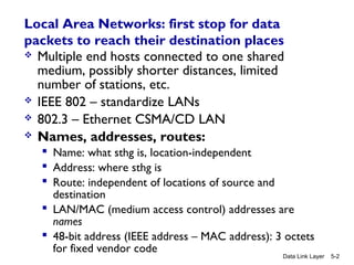
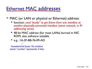
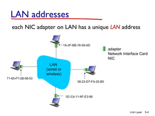
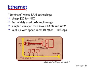
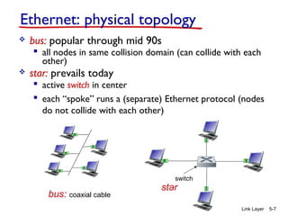
Chapter 5
Link Layer
Computer
Networking: A Top
Down Approach
6th
edition
Jim Kurose, Keith Ross
Addison-Wesley
March 2012
A note on the use of these ppt slides:
We’re making these slides freely available to all (faculty, students, readers).
They’re in PowerPoint form so you see the animations; and can add, modify,
and delete slides (including this one) and slide content to suit your needs.
They obviously represent a lot of work on our part. In return for use, we only
ask the following:
 If you use these slides (e.g., in a class) that you mention their source
(after all, we’d like people to use our book!)
 If you post any slides on a www site, that you note that they are adapted
from (or perhaps identical to) our slides, and note our copyright of this
material.
Thanks and enjoy! JFK/KWR
All material copyright 1996-2012
J.F Kurose and K.W. Ross, All Rights Reserved
Link Layer 5-1
Intro to first lab:
GENI experimentation testbed and MAC-LEARNING
Local Area Networks: first stop for data
packets to reach their destination places
 Multiple end hosts connected to one shared
medium, possibly shorter distances, limited
number of stations, etc.
 IEEE 802 – standardize LANs
 802.3 – Ethernet CSMA/CD LAN
 Names, addresses, routes:
 Name: what sthg is, location-independent
 Address: where sthg is
 Route: independent of locations of source and
destination
 LAN/MAC (medium access control) addresses are
names
 48-bit address (IEEE address – MAC address): 3 octets
for fixed vendor code
Data Link Layer 5-2
Link Layer 5-3
Ethernet MAC addresses
 MAC (or LAN or physical or Ethernet) address:
 function: used ‘locally” to get frame from one interface to
another physically-connected interface (same network, in IP-
addressing sense)
 48 bit MAC address (for most LANs) burned in NIC
ROM, also software settable
 e.g.: 1A-2F-BB-76-09-AD
hexadecimal (base 16) notation
(each “number” represents 4 bits)
Link Layer 5-4
LAN addresses
each NIC adapter on LAN has a unique LAN address
adapter
Network Interface Card
NIC
1A-2F-BB-76-09-AD
58-23-D7-FA-20-B0
0C-C4-11-6F-E3-98
71-65-F7-2B-08-53
LAN
(wired or
wireless)
Link Layer 5-5
LAN addresses (more)
 MAC address allocation administered by IEEE
 manufacturer buys portion of MAC address space
(to assure uniqueness)
 analogy:
 MAC address: like Social Security Number
 IP address: like postal address
 MAC flat address ➜ portability
 can move LAN card from one LAN to another
Link Layer 5-6
Ethernet
“dominant” wired LAN technology:
 cheap $20 for NIC
 first widely used LAN technology
 simpler, cheaper than token LANs and ATM
 kept up with speed race: 10 Mbps – 10 Gbps
Metcalfe’s Ethernet sketch
Link Layer 5-7
Ethernet: physical topology
 bus: popular through mid 90s
 all nodes in same collision domain (can collide with each
other)
 star: prevails today
 active switch in center
 each “spoke” runs a (separate) Ethernet protocol (nodes
do not collide with each other)
switch
bus: coaxial cable
star
Link Layer 5-8
Ethernet frame structure
sending adapter encapsulates IP datagram (or other
network layer protocol packet) in Ethernet frame
preamble:
 7 bytes with pattern 10101010 followed by one
byte with pattern 10101011
 used to synchronize receiver, sender clock rates
dest.
address
source
address
data
(payload) CRCpreamble
type
Link Layer 5-9
Ethernet frame structure (more)
 addresses: 6 byte source, destination MAC addresses
 if adapter receives frame with matching destination
address, or with broadcast address (e.g. ARP packet), it
passes data in frame to network layer protocol
 otherwise, adapter discards frame
 type: indicates higher layer protocol (mostly IP but
others possible, e.g., Novell IPX, AppleTalk)
 CRC: cyclic redundancy check at receiver
 error detected: frame is dropped
dest.
address
source
address
data
(payload) CRCpreamble
type
Link Layer 5-10
Ethernet: unreliable, connectionless
 connectionless: no handshaking between sending and
receiving NICs
 unreliable: receiving NIC doesn’t send acks or nacks
to sending NIC
 data in dropped frames recovered only if initial
sender uses higher layer reliable data transfer
protocols (e.g., TCP), otherwise dropped data lost
 Ethernet’s MAC protocol: unslotted CSMA/CD with
binary backoff algorithm
Link Layer 5-11
802.3 Ethernet standards: link & physical layers
 many different Ethernet standards
 common MAC protocol and frame format
 different speeds: 2 Mbps, 10 Mbps, 100 Mbps, 1Gbps,
10G bps
 different physical layer media: fiber, cable
application
transport
network
link
physical
MAC protocol
and frame format
100BASE-TX
100BASE-T4
100BASE-FX100BASE-T2
100BASE-SX 100BASE-BX
fiber physical layercopper (twister
pair) physical layer
Link Layer 5-12
Link layer, LANs: outline
5.1 introduction, services
5.4 LANs
 switches
 VLANS
Link Layer 5-13
Ethernet switch
 link-layer device: takes an active role
 store, forward Ethernet frames
 examine incoming frame’s destination MAC
address, selectively forward frame to one-or-
more outgoing links when frame is to be
forwarded on segment, uses CSMA/CD to
access segment
 transparent
 hosts are unaware of presence of switches
 plug-and-play, self-learning
 switches do not need to be configured
 MAC learning is automated
Link Layer 5-14
Switch: multiple simultaneous transmissions
 hosts have dedicated, direct
connection to switch
 switches buffer packets
 Ethernet protocol used on each
incoming link, but no collisions;
full duplex
 each link is its own collision
domain
 switching: A-to-D and B-to-E can
transmit simultaneously,
without collisions switch with six interfaces
(1,2,3,4,5,6)
A
D
B
E C
F
1 2
345
6
Link Layer 5-15
Switch forwarding table
Q: how does switch know D
reachable via interface 4, E
reachable via interface 5?
switch with six interfaces
(1,2,3,4,5,6)
A
D
B
E C
F
1 2
345
6 A: each switch has a switch
table, each entry:
 (MAC address of destination host,
interface to reach host, time
stamp)
Q: how are entries created,
maintained in switch table?
 Self-learning
A
D
B
E C
F
1 2
345
6
Link Layer 5-16
Switch: self-learning
 switch learns which hosts
can be reached through
which interfaces only when
a frame is received on an
incoming LAN segment
 records sender/location
pair in switch table
A D
Source: A
Dest: D
MAC addr interface TTL
Switch table
(initially empty)
A 1 60
A
D
B
E C
F
1 2
345
6
Link Layer 5-17
Self-learning, forwarding: example
A D
Source: A
Dest: D
MAC addr interface TTL
switch table
(initially empty)
A 1 60
A DA DA DA DA D
 frame destination, D,
location unknown: flood
D A
 destination A location
known:
D 4 60
selectively send
on just one link
Strategy of the Bridge (Switch)
 Listen promiscuously, receiving every packet transmitted
 For each incoming packet, store the SOURCE address of
the packet in a cache (station cache) + incoming (ingress)
port
 For each packet, look up in station cache to match on the
DESTINATION address of the packet
 No match: forward the packet on all ports except the incoming
port (= flooding)
 Match:
• forward on the port/interface specified in the station cache
• If interface/port is the same as incoming port, DROP
 “Age” each entry in the station cache so they expire after
some time (aging time)
Data Link Layer 5-18
GENI experimentation testbed
and self-LEARning
FIRST LAB
Data Link Layer 5-19

Lecture2 mac learning

  • 1.
    Chapter 5 Link Layer Computer Networking:A Top Down Approach 6th edition Jim Kurose, Keith Ross Addison-Wesley March 2012 A note on the use of these ppt slides: We’re making these slides freely available to all (faculty, students, readers). They’re in PowerPoint form so you see the animations; and can add, modify, and delete slides (including this one) and slide content to suit your needs. They obviously represent a lot of work on our part. In return for use, we only ask the following:  If you use these slides (e.g., in a class) that you mention their source (after all, we’d like people to use our book!)  If you post any slides on a www site, that you note that they are adapted from (or perhaps identical to) our slides, and note our copyright of this material. Thanks and enjoy! JFK/KWR All material copyright 1996-2012 J.F Kurose and K.W. Ross, All Rights Reserved Link Layer 5-1 Intro to first lab: GENI experimentation testbed and MAC-LEARNING
  • 2.
    Local Area Networks:first stop for data packets to reach their destination places  Multiple end hosts connected to one shared medium, possibly shorter distances, limited number of stations, etc.  IEEE 802 – standardize LANs  802.3 – Ethernet CSMA/CD LAN  Names, addresses, routes:  Name: what sthg is, location-independent  Address: where sthg is  Route: independent of locations of source and destination  LAN/MAC (medium access control) addresses are names  48-bit address (IEEE address – MAC address): 3 octets for fixed vendor code Data Link Layer 5-2
  • 3.
    Link Layer 5-3 EthernetMAC addresses  MAC (or LAN or physical or Ethernet) address:  function: used ‘locally” to get frame from one interface to another physically-connected interface (same network, in IP- addressing sense)  48 bit MAC address (for most LANs) burned in NIC ROM, also software settable  e.g.: 1A-2F-BB-76-09-AD hexadecimal (base 16) notation (each “number” represents 4 bits)
  • 4.
    Link Layer 5-4 LANaddresses each NIC adapter on LAN has a unique LAN address adapter Network Interface Card NIC 1A-2F-BB-76-09-AD 58-23-D7-FA-20-B0 0C-C4-11-6F-E3-98 71-65-F7-2B-08-53 LAN (wired or wireless)
  • 5.
    Link Layer 5-5 LANaddresses (more)  MAC address allocation administered by IEEE  manufacturer buys portion of MAC address space (to assure uniqueness)  analogy:  MAC address: like Social Security Number  IP address: like postal address  MAC flat address ➜ portability  can move LAN card from one LAN to another
  • 6.
    Link Layer 5-6 Ethernet “dominant”wired LAN technology:  cheap $20 for NIC  first widely used LAN technology  simpler, cheaper than token LANs and ATM  kept up with speed race: 10 Mbps – 10 Gbps Metcalfe’s Ethernet sketch
  • 7.
    Link Layer 5-7 Ethernet:physical topology  bus: popular through mid 90s  all nodes in same collision domain (can collide with each other)  star: prevails today  active switch in center  each “spoke” runs a (separate) Ethernet protocol (nodes do not collide with each other) switch bus: coaxial cable star
  • 8.
    Link Layer 5-8 Ethernetframe structure sending adapter encapsulates IP datagram (or other network layer protocol packet) in Ethernet frame preamble:  7 bytes with pattern 10101010 followed by one byte with pattern 10101011  used to synchronize receiver, sender clock rates dest. address source address data (payload) CRCpreamble type
  • 9.
    Link Layer 5-9 Ethernetframe structure (more)  addresses: 6 byte source, destination MAC addresses  if adapter receives frame with matching destination address, or with broadcast address (e.g. ARP packet), it passes data in frame to network layer protocol  otherwise, adapter discards frame  type: indicates higher layer protocol (mostly IP but others possible, e.g., Novell IPX, AppleTalk)  CRC: cyclic redundancy check at receiver  error detected: frame is dropped dest. address source address data (payload) CRCpreamble type
  • 10.
    Link Layer 5-10 Ethernet:unreliable, connectionless  connectionless: no handshaking between sending and receiving NICs  unreliable: receiving NIC doesn’t send acks or nacks to sending NIC  data in dropped frames recovered only if initial sender uses higher layer reliable data transfer protocols (e.g., TCP), otherwise dropped data lost  Ethernet’s MAC protocol: unslotted CSMA/CD with binary backoff algorithm
  • 11.
    Link Layer 5-11 802.3Ethernet standards: link & physical layers  many different Ethernet standards  common MAC protocol and frame format  different speeds: 2 Mbps, 10 Mbps, 100 Mbps, 1Gbps, 10G bps  different physical layer media: fiber, cable application transport network link physical MAC protocol and frame format 100BASE-TX 100BASE-T4 100BASE-FX100BASE-T2 100BASE-SX 100BASE-BX fiber physical layercopper (twister pair) physical layer
  • 12.
    Link Layer 5-12 Linklayer, LANs: outline 5.1 introduction, services 5.4 LANs  switches  VLANS
  • 13.
    Link Layer 5-13 Ethernetswitch  link-layer device: takes an active role  store, forward Ethernet frames  examine incoming frame’s destination MAC address, selectively forward frame to one-or- more outgoing links when frame is to be forwarded on segment, uses CSMA/CD to access segment  transparent  hosts are unaware of presence of switches  plug-and-play, self-learning  switches do not need to be configured  MAC learning is automated
  • 14.
    Link Layer 5-14 Switch:multiple simultaneous transmissions  hosts have dedicated, direct connection to switch  switches buffer packets  Ethernet protocol used on each incoming link, but no collisions; full duplex  each link is its own collision domain  switching: A-to-D and B-to-E can transmit simultaneously, without collisions switch with six interfaces (1,2,3,4,5,6) A D B E C F 1 2 345 6
  • 15.
    Link Layer 5-15 Switchforwarding table Q: how does switch know D reachable via interface 4, E reachable via interface 5? switch with six interfaces (1,2,3,4,5,6) A D B E C F 1 2 345 6 A: each switch has a switch table, each entry:  (MAC address of destination host, interface to reach host, time stamp) Q: how are entries created, maintained in switch table?  Self-learning
  • 16.
    A D B E C F 1 2 345 6 LinkLayer 5-16 Switch: self-learning  switch learns which hosts can be reached through which interfaces only when a frame is received on an incoming LAN segment  records sender/location pair in switch table A D Source: A Dest: D MAC addr interface TTL Switch table (initially empty) A 1 60
  • 17.
    A D B E C F 1 2 345 6 LinkLayer 5-17 Self-learning, forwarding: example A D Source: A Dest: D MAC addr interface TTL switch table (initially empty) A 1 60 A DA DA DA DA D  frame destination, D, location unknown: flood D A  destination A location known: D 4 60 selectively send on just one link
  • 18.
    Strategy of theBridge (Switch)  Listen promiscuously, receiving every packet transmitted  For each incoming packet, store the SOURCE address of the packet in a cache (station cache) + incoming (ingress) port  For each packet, look up in station cache to match on the DESTINATION address of the packet  No match: forward the packet on all ports except the incoming port (= flooding)  Match: • forward on the port/interface specified in the station cache • If interface/port is the same as incoming port, DROP  “Age” each entry in the station cache so they expire after some time (aging time) Data Link Layer 5-18
  • 19.
    GENI experimentation testbed andself-LEARning FIRST LAB Data Link Layer 5-19