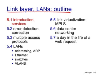
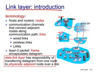
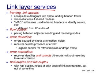
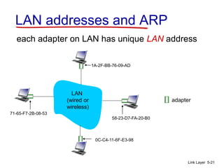
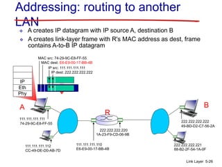
The document provides an overview of the link layer. It discusses the goals and services of the link layer, including error detection, correction, and sharing access to broadcast channels through multiple access protocols. It describes various link layer technologies like Ethernet, switches, and VLANs. It also covers topics like link layer addressing using MAC addresses, the Address Resolution Protocol (ARP) for mapping IP addresses to MAC addresses, and examples of multiple access protocols including Carrier Sense Multiple Access with Collision Detection (CSMA/CD) used in Ethernet networks.
This document discusses the link layer and local area networks. It begins with an introduction to link layer services including framing, link access, reliable delivery, flow control, and error detection and correction. It then covers topics like multiple access protocols, including random access protocols like ALOHA and CSMA, and controlled access protocols. Local area network technologies are discussed next, focusing on Ethernet, switches, and addressing protocols like ARP. The document concludes with sections on link virtualization using MPLS and data center networking.
The document discusses data link layer protocols and multiple access protocols. It describes several protocols for sharing a broadcast channel, including slotted ALOHA, CSMA, CSMA/CD, and token passing. It also discusses error detection techniques like parity checking and cyclic redundancy checks used at the data link layer. The goal of the data link layer is to reliably transfer data frames between adjacent nodes over a link using addressing, error detection, flow control and other services.
“MPLS is that it’s a technique, not a service.”
The fundamental concept behind MPLS is that of labeling packets. In a traditional routed IP network,
each router makes an independent forwarding decision for each packet based solely on the packet’s
network-layer header. Thus, every time a packet arrives at a router, the router has to “think through”
where to send the packet next.
This document contains slides summarizing key concepts about network layer control planes from the textbook "Computer Networking: A Top Down Approach". The slides cover traditional routing algorithms like link state (e.g. Dijkstra's algorithm) and distance vector (e.g. Bellman-Ford), as well as software defined networking control planes. Specific routing protocols discussed include OSPF, BGP, OpenFlow and SDN controllers. The document also mentions ICMP and network management using SNMP.
The document provides an overview of MPLS (Multi-Protocol Label Switching) concepts and components. It discusses how MPLS separates routing from forwarding by using labels to forward packets based on the label rather than the IP address. It describes MPLS components like edge label switching routers (ELSR or PE), label switching routers (LSR or P), and the label distribution protocol (LDP). It also provides examples of MPLS forwarding and MPLS VPN operation.
this pdf contain simple method to install one of important MPLS service MPLS L3VPN and explain how mpls distribute labels
use simple routing protocol with customer (static route) to initiate L3VPN
This document provides an overview of Point-to-Point Protocol (PPP) including how it is used to encapsulate TCP/IP and other network layer protocols over dial-up connections. PPP uses the Link Control Protocol (LCP) to establish and configure connections, and the Network Control Protocol (NCP) to establish specific network layer protocols. The document discusses how to configure PPP encapsulation on an interface and assign IP addresses to remote users. It also covers PPP authentication using PAP and CHAP as well as other PPP features negotiated by LCP such as compression and Multilink PPP.
The document summarizes key concepts about the data link layer. It discusses the goals and services of the data link layer, including error detection and correction, sharing broadcast channels through multiple access protocols, link layer addressing, and reliable data transfer and flow control. It also provides an overview of common link layer technologies and implementation through instantiation of various data link layer protocols.
AODV (Ad hoc On-demand Distance Vector) VS AOMDV (Ad hoc On-demand Multipath ...Ann Joseph
The document discusses Ad hoc On-demand Multipath Distance Vector (AOMDV), which is a multipath extension of the AODV routing protocol for mobile ad hoc networks. AOMDV discovers multiple loop-free and disjoint paths between source and destination nodes in a single route discovery to improve fault tolerance. It provides benefits like lower end-to-end delay, higher throughput, and reduced route discovery operations compared to AODV, which is a single path routing protocol.
Tutorial about MPLS Implementation with Cisco Router, this second of two chapter discuss about MPLS Configuration, LDP Configuration, VPN Services, L2VPN (VLL & VPLS) and L3VPN (VPRN).
it also contain case study and implementation of VLL, VPLS, and VPRN
- MPLS stands for Multi-Protocol Label Switching and was originally introduced to improve router forwarding speeds and meet bandwidth management requirements in IP networks.
- MPLS uses labels to forward packets based on their destination rather than long IP addresses. Label Edge Routers assign labels and interface with external networks, while Label Switch Routers in the core switch packets based on their labels.
- MPLS establishes Label Switched Paths between ingress and egress routers to efficiently route packets through the network based on forwarding tables that map incoming to outgoing labels. This allows traffic engineering and quality of service control.
Multi-Protocol Label Switching has become by far one of the most important Internet technologies of the last 15 years. From humble beginnings back in 1996-97, it is literally the defacto standard in a large majority of service provider networks today. This presentation, delivered to executives at MTNL, Mumbai (a large regional carrier in India), explains the key operational principles behind MPLS, and its significant applications.
This document provides an overview and agenda for a presentation on VXLAN BGP EVPN technology. It begins with an introduction to VXLAN and EVPN concepts. It then outlines the agenda which includes explaining VXLAN configuration, EVPN configuration, underlay configuration, overlay configuration, and EVPN VXLAN service configuration. It also provides a sample migration from a legacy device configuration to a VXLAN BGP EVPN configuration. Various networking acronyms related to VXLAN and EVPN are defined. Sample vendor supported data center technologies and a VXLAN test topology are shown.
Overview of the MPLS backbone transmission technology.
MPLS (MultiProtocol Layer Switching) is a layer 2.5 technology that combines the virtues of IP routing and fast layer 2 packet switching.
IP packet forwarding is not suited for high-speed forwarding due to the need to evaluate multiple routes for each IP packet in order to find the optimal route, i.e. the route with the longest prefix match.
However, Internet Protocol routing provides global reachability through the IP address and through IP routing protocols like BGP or OSPF.
Layer 2 packet switching has complementary characteristics in that it does not provide global reachability through globally unique addresses but allows fast packet forwarding in hardware through the use of small and direct layer 2 lookup addresses.
MPLS combines IP routing and layer 2 switching by establishing layer 2 forwarding paths based on routes received through IP routing protocols like BGP or OSPF.
Thus the control plane of an MPLS capable device establishes layer 2 forwarding paths while the data plane then performs packet forwarding, often in hardware.
MPLS is not a layer 2 technology itself, i.e. it does not define a layer 2 protocol but rather makes use of existing layer 2 technologies like Ethernet, ATM or Frame Relay.
- This chapter discusses switching and VLANs, including Fast Ethernet, full- and half-duplex Ethernet operations, LAN switching methods like cut-through and store-and-forward, and the Spanning Tree Protocol. It also defines virtual LANs (VLANs) and how they segment networks logically without changing the physical configuration. VLAN trunking protocols are used to communicate VLAN information between switches.
The document discusses medium access control (MAC) protocols for wireless ad-hoc networks. It describes several MAC protocols including the Five Phase Reservation Protocol (FPRP) and Distributed Wireless Ordering Protocol (DWOP). FPRP uses a five phase process for distributed reservation of time slots. DWOP aims to provide fair channel access that approximates a first-in-first-out scheduling order by sharing packet arrival times between nodes. The document evaluates these protocols and discusses their advantages in providing quality of service guarantees and fair scheduling in wireless ad-hoc networks.
The document discusses several topics related to computer network models and protocols. It describes the OSI model which consists of seven layers and was developed by ISO to ensure worldwide data communication. It also discusses the TCP/IP model. The network layer is described in detail, covering functions like routing packets between networks and logical to physical address translation. Store-and-forward packet switching is explained. The transport layer provides services like port addressing, segmentation and reassembly, and connection-oriented and connectionless transmission. IP addressing schemes like classful and classless are summarized. Network protocols such as ARP, DHCP, ICMP, and RIP are also mentioned briefly.
1) MPLS introduces labels that are prefixed to packet headers and allows forwarding based on these labels instead of long IP addresses, enabling traffic engineering.
2) Labels are assigned based on forward equivalence classes which group packets that should follow the same path. This path is called a label switched path (LSP).
3) Generalized MPLS (GMPLS) extends MPLS to support a wider range of network types and interfaces beyond IP routers, including support for optical and time-division multiplexing networks. It enhances signaling protocols and introduces hierarchical LSP setup.
Tutorial about MPLS Implementation with Cisco Router, this first of two chapter discuss about What is MPLS, Network Design, P, PE, and CE Router Description, Case Study of IP MPLS Implementation, IP and OSPF Routing Configuration
1) The document describes the Ad Hoc On-Demand Distance Vector (AODV) routing protocol. AODV is a reactive protocol that discovers routes on-demand using a route discovery process.
2) When a node needs to send a packet to an unknown destination, it broadcasts a route request (RREQ) to its neighbors. Neighbors set up reverse paths and rebroadcast the RREQ until it reaches the destination node.
3) The destination or intermediate nodes with a route can send a unicast route reply (RREP) back to the source node using the reverse path. This sets up a forward path from source to destination for data packets.
Fast Ethernet increased the bandwidth of standard Ethernet from 10 Mbps to 100 Mbps. It used the same CSMA/CD access method and frame format as standard Ethernet but with some changes to address the higher speed. Fast Ethernet was implemented over twisted pair cables using 100BASE-TX or over fiber optic cables using 100BASE-FX. The increased speed enabled Fast Ethernet to compete with other high-speed LAN technologies of the time like FDDI.
PPP and HDLC are point-to-point protocols used at the data link layer. PPP provides connection management, parameter negotiation, and supports multiple network layer protocols. It is commonly used for dial-up and broadband connections. HDLC also supports point-to-point and multi-point connections with frame formatting and error detection. Both protocols provide reliable data transfer through mechanisms like sequence numbers, acknowledgments, and error checking.
Frame Relay uses virtual circuits to connect devices over a connection-oriented network. It operates at the data link layer of the OSI model and can use various physical layer protocols. Frame Relay maps network layer addresses like IP addresses to data-link connection identifiers (DLCIs) which are used to forward frames through the Frame Relay network.
The document summarizes several routing protocols used in wireless networks. It discusses both table-driven protocols like DSDV and on-demand protocols like AODV. It provides details on how each protocol performs routing and maintains routes. It also outlines some advantages and disadvantages of protocols like DSDV, AODV, DSR, and TORA.
The document discusses the link layer and provides an overview of its goals and services including error detection, multiple access protocols, and local area networks. It outlines the topics that will be covered in the chapter including error detection and correction, multiple access protocols like CSMA/CD, addressing in LANs, Ethernet, switches, and VLANs. The slides are being made freely available for educational use provided proper attribution is given.
Medium Access PROTOCOL b yENGR. FAWAD KHAN UET BANNU KP PAKISTANirfan sami
1. The document discusses medium access control (MAC) protocols for shared broadcast links at the link layer. It covers three main classes of MAC protocols: channel partitioning, random access, and "taking turns" protocols.
2. Channel partitioning protocols like TDMA and FDMA divide the channel into time or frequency slots and allocate slots to nodes. Random access protocols like ALOHA, CSMA, and CSMA/CD allow nodes to transmit randomly and include mechanisms to detect and handle collisions. "Taking turns" protocols such as polling and token passing coordinate channel access by having nodes take turns transmitting.
3. The ideal MAC protocol allows single or multiple nodes to transmit at the maximum channel rate, is fully decentralized, requires
The document discusses the link layer and provides an overview of its services and functions. It describes multiple access protocols for shared mediums including ALOHA, slotted ALOHA, CSMA, CSMA/CD. CSMA/CD is used in Ethernet and detects collisions to reduce wasted bandwidth. The document outlines error detection methods like parity checking, cyclic redundancy checks, and discusses how the link layer is implemented in network interface cards.
This document discusses the link layer and provides an overview of its services and context. It describes how the link layer is implemented in network interface cards and how these cards encapsulate datagrams into frames. It also outlines the topics to be covered, including error detection and correction, multiple access protocols, local area networks, and link virtualization.
Data centers architecture and design guideMattPeci
Data center architecture, as an architectural design that establishes connections between switches and servers, is typically created during the data center design and construction phases
This document discusses data center network architectures. It begins by noting that data centers contain tens to hundreds of thousands of closely coupled hosts in close proximity, posing challenges around load management and avoiding bottlenecks. It then describes common data center network components like server racks, top-of-rack switches, core switches, and load balancers. Load balancers direct external client requests and hide the internal data center structure. The network uses a rich interconnection of switches and racks for increased throughput and redundancy. Broad questions are raised around networking massive numbers of machines, virtualization resource management, and reducing operational costs like power.
The document discusses link layer concepts including link layer addressing, MAC addresses, ARP, Ethernet frames, CSMA/CD, hubs, and switches. It explains that MAC addresses are used to deliver frames within a local area network, while IP addresses are used between networks. ARP is used to map IP addresses to MAC addresses on the same network. Ethernet uses CSMA/CD for media access and frames include source and destination MAC addresses. Hubs operate at the physical layer while switches operate at the data link layer and can reduce collisions by isolating segments.
The document discusses link layer protocols and multiple access protocols. It provides examples of channel partitioning protocols like TDMA and FDMA that divide the channel into time slots or frequency bands. It also discusses random access protocols like ALOHA, slotted ALOHA, and CSMA/CD that do not partition the channel and can result in collisions. CSMA/CD improves on CSMA by allowing nodes to detect collisions and abort transmissions to reduce wasted bandwidth. "Taking turns" protocols like polling and token passing allocate channel access by turning to control which node can transmit.
Lecture 25 Link Layer - Error detection and Multiple Access.pptxHanzlaNaveed1
The document discusses principles of link layer services including error detection, correction, and sharing a broadcast channel through multiple access protocols. It provides an overview of topics like link layer addressing, local area networks including Ethernet and VLANs. Specific link layer services covered are error detection using techniques like parity checking and cyclic redundancy check (CRC). The document also distinguishes between point-to-point and broadcast links, and describes multiple access protocols for shared broadcast channels including TDMA, FDMA, and random access protocols like slotted ALOHA and CSMA.
The document discusses the link layer and its services. It introduces key link layer concepts like framing, link access, error detection, flow control, and multiple access protocols. It describes different types of multiple access protocols including channel partitioning protocols like TDMA and FDMA as well as random access protocols like ALOHA and CSMA. It also discusses error detection techniques like parity checking, checksums, and cyclic redundancy checks (CRCs). The document provides examples and comparisons of protocols to convey their tradeoffs and how they address the challenges of sharing communication channels.
This document provides an overview and outline of topics to be covered in a chapter about the link layer and local area networks (LANs). It discusses the goals of understanding link layer services like error detection and correction as well as sharing bandwidth on a broadcast channel. It also outlines the key sections to be covered, including multiple access protocols, LAN addressing, Ethernet, switches, and virtual LANs. Sample slides are provided on topics like link layer services, error detection techniques, and multiple access protocols. The document is intended for educational use and asks that the source be cited if used for teaching.
This document provides an overview and summary of a chapter on link layers and local area networks (LANs) from the textbook "Computer Networking: A Top-Down Approach". It discusses the goals of understanding link layer services and technologies. It also provides an outline of the chapter topics which include error detection and correction, multiple access protocols, LAN addressing, Ethernet, switches, and virtual LANs. The document is intended for educational use and free modification with attribution required.
Local area networks can use different topologies and transmission mediums. Common topologies include bus, ring, and star. Transmission mediums include twisted pair cable, coaxial cable, and fiber optic cable. Bridges connect different LANs and repeat frames between them in a transparent manner. Spanning tree protocols allow bridges to dynamically establish loop-free routes between LANs. Layer 2 switches improve performance over shared bus and hub architectures by providing dedicated bandwidth to each connected device.
The document discusses broadcast networks and medium access control (MAC) protocols. It introduces the concepts of broadcast networks, where a single shared medium allows all connected devices to receive messages. This leads to potential conflicts when multiple devices try to transmit simultaneously. MAC protocols are needed to coordinate transmissions and resolve conflicts. Common MAC protocols discussed include ALOHA, CSMA, CSMA/CD (Ethernet), and token passing (Token Ring). LAN standards like IEEE 802.3 that define MAC sublayer functions for CSMA/CD networks are also summarized briefly.
An e-market, or electronic market, is a virtual marketplace where buyers and sellers can engage in transactions through the use of digital platforms, such as websites, mobile apps, or social media. E-markets have become increasingly popular in recent years due to their convenience, accessibility, and global reach.
E-markets differ from traditional markets in several ways:
Global reach: E-markets have a global reach, allowing buyers and sellers to connect from anywhere in the world. This means that businesses can access new markets and reach customers that they may not have been able to reach through traditional channels.
Convenience: E-markets offer a high degree of convenience, allowing customers to shop from the comfort of their homes or on the go using mobile devices. This convenience factor can lead to higher customer satisfaction and loyalty.
Lower overhead costs: E-markets typically have lower overhead costs than traditional markets, as they do not require physical storefronts, inventory storage, or other infrastructure. This can result in lower prices for customers and higher profit margins for businesses.
24/7 availability: E-markets are available 24/7, allowing customers to shop at any time of the day or night. This can be particularly advantageous for businesses that operate in multiple time zones or that cater to customers with varying schedules.
Greater competition: E-markets can be highly competitive, with many businesses vying for the attention and loyalty of customers. This can result in lower prices, higher quality products, and better customer service as businesses compete for market share.
The document compares MAC protocols in wired and wireless systems. In wired systems, protocols like Ethernet use CSMA/CD, allowing nodes to detect collisions. In wireless systems, hidden and exposed terminal problems occur, requiring protocols like MACA, MACAW, and 802.11 CSMA/CA to use RTS/CTS handshaking or polling to avoid interference between transmissions. The IEEE 802.11 standard defines distributed and point coordination function MAC methods for wireless LANs.
Ethernet is a family of local area network (LAN) protocols that was first developed in 1976. It uses bus or star topologies and supports data transfer rates of 10/100/1000 Mbps. Fast Ethernet was developed to support higher speeds of 100 Mbps, while Gigabit Ethernet supports 1000 Mbps. Ethernet uses CSMA/CD to handle simultaneous transmission demands in half-duplex mode, while full-duplex mode allows simultaneous transmission in both directions. Token ring is another common LAN protocol that uses a token passing mechanism to control access instead of CSMA/CD.
This document summarizes key topics from Chapter 5 of the textbook "Computer Networking: A Top Down Approach". It discusses:
- The link layer, which encapsulates datagrams into frames and transfers them between adjacent nodes. Different link layer protocols may be used on different links.
- Link layer services like framing, reliable delivery between nodes, error detection, flow control, and more. These services are implemented in network interface cards.
- Multiple access protocols that coordinate access to shared broadcast links, including TDMA, FDMA, ALOHA, and CSMA.
- Switches, which examine frame addresses and selectively forward frames to the correct outgoing link, avoiding collisions. Switches learn node
Tocci chapter 13 applications of programmable logic devices extendedcairo university
The document discusses the family tree of digital systems, including standard logic, ASICs, microprocessors, DSPs, and different types of programmable logic devices like PLDs, CPLDs, and FPGAs. It covers the architectures of early PLDs like PROM, PAL, and FPLA, which have programmable AND and OR gates, as well as the different programming technologies for modern PLDs like SRAM, flash memory, EPROM, and antifuse.
The document discusses various types of memory devices and technologies. It covers topics like memory terminology, ROM, EPROM, EEPROM, and flash memory. Key points include that ROM is read-only memory that can be mask-programmed or one-time programmable, while EPROM, EEPROM and flash memory use floating-gate MOS transistors and can be electrically erased and reprogrammed in bulk or individually.
This document covers MSI (medium-scale integration) logic circuits. It discusses decoders, multiplexers, encoders, and other digital logic components. Decoders take binary inputs and activate one of multiple outputs. Multiplexers select one of several inputs to output based on a digital select code. Encoders convert coded inputs to binary outputs. The document provides circuit diagrams and explanations of common MSI components like decoders, multiplexers, priority encoders, and code converters. It also discusses applications such as seven-segment displays, LCDs, and digital systems.
This document discusses various types of counters and registers, including asynchronous (ripple) counters, synchronous (parallel) counters, decade counters, BCD counters, shift registers, ring counters, and Johnson counters. It provides details on their structure, operation, and applications. Key topics covered include propagation delay in ripple counters, the advantages of synchronous counters, designing counters with different mod numbers, decoding counter states, and using counters for functions like stepper motor control.
Tocci ch 6 digital arithmetic operations and circuitscairo university
The document discusses digital arithmetic operations and circuits, including binary addition, representing signed numbers, addition and subtraction in the two's complement system, multiplication and division of binary numbers, BCD addition, hexadecimal arithmetic, and arithmetic circuits. It describes how an ALU performs arithmetic operations by accepting data from memory and executing instructions from the control unit, using adders, registers, and control signals to perform addition and subtraction.
Tocci ch 3 5 boolean algebra, logic gates, combinational circuits, f fs, - re...cairo university
This document contains lecture slides on logic gates and Boolean algebra. It covers topics like De Morgan's theorem, sum of products and product of sums, logic gate representations including NAND and NOR gates, flip flops including JK and D flip flops. Circuit diagrams and truth tables are provided for latching circuits and different types of flip flops. The document is copyrighted and appears to be from a course on logic gates and Boolean algebra taught by Muhammad A M Islam.
The document discusses latches and flip-flops, basic memory circuits. It describes the latch, SR flip-flop, CMOS enabled SR flip-flop, and CMOS SRAM memory cell. It also discusses a one-transistor dynamic RAM cell. The document focuses on the circuit designs and operations of various basic memory components.
A14 sedra ch 14 advanced mos and bipolar logic circuitscairo university
This document discusses advanced logic circuits including pseudo-NMOS logic, pass-transistor logic, dynamic MOS logic, emitter-coupled logic (ECL), and BiCMOS digital circuits. Pseudo-NMOS logic uses one transistor per input instead of two to reduce area and delay. Pass-transistor logic builds logic functions using NMOS or transmission gate switches. Dynamic MOS logic uses precharge and evaluate phases to reduce static power at the cost of increased sensitivity to noise. ECL uses differential pairs for noise immunity and constant current sources. BiCMOS combines CMOS and BJTs to achieve high performance with lower power than ECL.
This document discusses CMOS digital logic circuits. It covers special characteristics like fan-out, power dissipation, and propagation delay. It then describes the basic CMOS inverter circuit. The inverter uses complementary NMOS and PMOS transistors for the pull-down and pull-up networks. When the input is low, the NMOS transistor is on and the PMOS is off, pulling the output high. When the input is high, the opposite occurs. This allows the output to switch between 0V and the supply voltage with very low static power dissipation.
The document discusses the high-frequency response of common-emitter (CE) amplifiers. It first examines the CE amplifier circuit and its mid-band behavior when the capacitors are short circuits. It then explores how each internal capacitor (CB, CC, CE) affects the frequency response as it blocks signal flow at lower frequencies. The document also considers the Miller effect, which multiplies the input capacitance seen at the base due to feedback through the amplifier. Overall, the internal capacitances lower the amplifier's bandwidth as frequency decreases.
This document describes the structure and operation of MOS field-effect transistors (MOSFETs). It covers topics such as device structure, current-voltage characteristics, MOSFET circuits at DC, and large-signal equivalent circuit models. Examples are provided to illustrate how to analyze MOSFET circuits and calculate current and voltage values. The document also discusses the physical mechanisms involved in MOSFET operation such as creation of a channel for current flow and derivation of current-voltage relationships.
This document discusses MOS field-effect transistors (MOSFETs) and includes the following topics:
1. It outlines the structure and operation of MOSFET devices, including creating a channel for current flow and deriving the iD-vDS relationship.
2. It covers current-voltage characteristics of MOSFETs such as the iD-vDS, iD-vGS curves and their different operating regions.
3. It provides examples of solving for unknown variables in MOSFET circuits operating in different regions, such as the triode and saturation regions.
This document discusses MOS field-effect transistors (MOSFETs) and their operation. It covers MOSFET device structure and physical operation, current-voltage characteristics, MOSFET circuits at DC, applying MOSFETs in amplifier design, small signal operations and models, and other related topics. The document contains diagrams and equations to illustrate MOSFET characteristics and circuit analysis. It provides an overview of the key concepts and applications of MOSFET devices.
This document discusses coordinate systems and vector calculus concepts needed for electromagnetic field theory. It introduces Cartesian, cylindrical, and spherical coordinate systems. It explains that vector integration requires defining appropriate differential elements (length, area, volume) that vary based on the coordinate system. It also introduces concepts of gradient, divergence, and curl - vector operators used to take derivatives of vector fields. The gradient represents the maximum rate of change, divergence measures flux, and curl represents rotational nature. Expressions for these operators are given in the three coordinate systems.
The document discusses the interaction of electromagnetic fields (EMFs) with biological systems. It notes that the topic is studied to assess potential health hazards, enable applications in biology and medicine, and optimize the design of EM devices. The document outlines various effects of EMF exposure at different frequencies, therapeutic and diagnostic EMF applications, and the need to model human exposure and effects through governing equations and human body models. Key areas covered include dosimetry, various human body models, RF applications like keyless entry and MRI, hyperthermia modeling, and diagnostic applications such as endoscopic capsules.
1. The document discusses various electromagnetic boundary conditions including:
- Electric and magnetic field boundary conditions between dielectric-dielectric interfaces where the normal component of B and tangential component of E are continuous.
- Conductor-dielectric boundary conditions where the surface charge density is related to the normal electric field component.
2. Faraday's law relates the rate of change of magnetic flux through a loop to the induced electromotive force around the loop. Lenz's law states that the induced current will flow such that it creates a magnetic field opposing the original change in flux.
3. The plane wave solution for electromagnetic waves in free space represents the electric and magnetic fields as propagating sinusoidal functions of space and time with
Electrical stimulation can be used for many applications including vision restoration, epilepsy control, tremor control, cardiac pacing, and more. Magnetic fields are generated by moving electric charges. The Biot-Savart law describes the magnetic field generated by a current element, while Ampere's law relates the magnetic field to the current passing through a closed loop. Materials respond differently to magnetic fields based on properties like diamagnetism, paramagnetism, and ferromagnetism. Ferromagnetic materials have domains that can align with an external magnetic field, allowing the material to retain magnetization.
Here are some examples of FDA-approved therapeutic devices that use direct current (DC) electric fields:
- Bone growth stimulators - Use pulsed electromagnetic fields or capacitively coupled electric fields to promote bone healing of fractures that are not healing on their own.
- Transcutaneous electrical nerve stimulators (TENS) - Apply electric currents to stimulate nerves for pain relief and muscle rehabilitation.
- Iontophoresis devices - Use low-level electrical currents to drive ionized drug molecules through the skin for local drug delivery.
- Cardioversion/defibrillation devices - Apply controlled electric shocks to the heart to treat irregular heart rhythms like atrial fibrillation or ventricular fibrillation.
The document provides an overview of the Silicon Labs C8051F020 microcontroller. It describes the microcontroller's CPU, memory organization, I/O ports, analog and digital peripherals such as ADCs, DACs, and comparators. It also discusses the microcontroller's special function registers used to control and interface with its various peripherals.
Lecture 1 (course overview and 8051 architecture) rv01cairo university
This document provides an overview and syllabus for a course on the 8051 microcontroller architecture. The course covers the 8051 architecture, instruction set, programming using assembly and C languages, peripherals, interrupts, timers, serial communication, analog-to-digital converters, and more. The goals are for students to understand the 8051 architecture, develop skills in programming 8051 microcontrollers using different languages, and interface the microcontroller to external components. The course consists of lectures, tutorials, and labs using the Silicon Labs C8051F020 development board.
The CBC machine is a common diagnostic tool used by doctors to measure a patient's red blood cell count, white blood cell count and platelet count. The machine uses a small sample of the patient's blood, which is then placed into special tubes and analyzed. The results of the analysis are then displayed on a screen for the doctor to review. The CBC machine is an important tool for diagnosing various conditions, such as anemia, infection and leukemia. It can also help to monitor a patient's response to treatment.
International Conference on NLP, Artificial Intelligence, Machine Learning an...gerogepatton
International Conference on NLP, Artificial Intelligence, Machine Learning and Applications (NLAIM 2024) offers a premier global platform for exchanging insights and findings in the theory, methodology, and applications of NLP, Artificial Intelligence, Machine Learning, and their applications. The conference seeks substantial contributions across all key domains of NLP, Artificial Intelligence, Machine Learning, and their practical applications, aiming to foster both theoretical advancements and real-world implementations. With a focus on facilitating collaboration between researchers and practitioners from academia and industry, the conference serves as a nexus for sharing the latest developments in the field.
Software Engineering and Project Management - Introduction, Modeling Concepts...Prakhyath Rai
Introduction, Modeling Concepts and Class Modeling: What is Object orientation? What is OO development? OO Themes; Evidence for usefulness of OO development; OO modeling history. Modeling
as Design technique: Modeling, abstraction, The Three models. Class Modeling: Object and Class Concept, Link and associations concepts, Generalization and Inheritance, A sample class model, Navigation of class models, and UML diagrams
Building the Analysis Models: Requirement Analysis, Analysis Model Approaches, Data modeling Concepts, Object Oriented Analysis, Scenario-Based Modeling, Flow-Oriented Modeling, class Based Modeling, Creating a Behavioral Model.
Advanced control scheme of doubly fed induction generator for wind turbine us...IJECEIAES
This paper describes a speed control device for generating electrical energy on an electricity network based on the doubly fed induction generator (DFIG) used for wind power conversion systems. At first, a double-fed induction generator model was constructed. A control law is formulated to govern the flow of energy between the stator of a DFIG and the energy network using three types of controllers: proportional integral (PI), sliding mode controller (SMC) and second order sliding mode controller (SOSMC). Their different results in terms of power reference tracking, reaction to unexpected speed fluctuations, sensitivity to perturbations, and resilience against machine parameter alterations are compared. MATLAB/Simulink was used to conduct the simulations for the preceding study. Multiple simulations have shown very satisfying results, and the investigations demonstrate the efficacy and power-enhancing capabilities of the suggested control system.
Redefining brain tumor segmentation: a cutting-edge convolutional neural netw...IJECEIAES
Medical image analysis has witnessed significant advancements with deep learning techniques. In the domain of brain tumor segmentation, the ability to
precisely delineate tumor boundaries from magnetic resonance imaging (MRI)
scans holds profound implications for diagnosis. This study presents an ensemble convolutional neural network (CNN) with transfer learning, integrating
the state-of-the-art Deeplabv3+ architecture with the ResNet18 backbone. The
model is rigorously trained and evaluated, exhibiting remarkable performance
metrics, including an impressive global accuracy of 99.286%, a high-class accuracy of 82.191%, a mean intersection over union (IoU) of 79.900%, a weighted
IoU of 98.620%, and a Boundary F1 (BF) score of 83.303%. Notably, a detailed comparative analysis with existing methods showcases the superiority of
our proposed model. These findings underscore the model’s competence in precise brain tumor localization, underscoring its potential to revolutionize medical
image analysis and enhance healthcare outcomes. This research paves the way
for future exploration and optimization of advanced CNN models in medical
imaging, emphasizing addressing false positives and resource efficiency.
Batteries -Introduction – Types of Batteries – discharging and charging of battery - characteristics of battery –battery rating- various tests on battery- – Primary battery: silver button cell- Secondary battery :Ni-Cd battery-modern battery: lithium ion battery-maintenance of batteries-choices of batteries for electric vehicle applications.
Fuel Cells: Introduction- importance and classification of fuel cells - description, principle, components, applications of fuel cells: H2-O2 fuel cell, alkaline fuel cell, molten carbonate fuel cell and direct methanol fuel cells.
CHINA’S GEO-ECONOMIC OUTREACH IN CENTRAL ASIAN COUNTRIES AND FUTURE PROSPECTjpsjournal1
The rivalry between prominent international actors for dominance over Central Asia's hydrocarbon
reserves and the ancient silk trade route, along with China's diplomatic endeavours in the area, has been
referred to as the "New Great Game." This research centres on the power struggle, considering
geopolitical, geostrategic, and geoeconomic variables. Topics including trade, political hegemony, oil
politics, and conventional and nontraditional security are all explored and explained by the researcher.
Using Mackinder's Heartland, Spykman Rimland, and Hegemonic Stability theories, examines China's role
in Central Asia. This study adheres to the empirical epistemological method and has taken care of
objectivity. This study analyze primary and secondary research documents critically to elaborate role of
china’s geo economic outreach in central Asian countries and its future prospect. China is thriving in trade,
pipeline politics, and winning states, according to this study, thanks to important instruments like the
Shanghai Cooperation Organisation and the Belt and Road Economic Initiative. According to this study,
China is seeing significant success in commerce, pipeline politics, and gaining influence on other
governments. This success may be attributed to the effective utilisation of key tools such as the Shanghai
Cooperation Organisation and the Belt and Road Economic Initiative.
CHINA’S GEO-ECONOMIC OUTREACH IN CENTRAL ASIAN COUNTRIES AND FUTURE PROSPECT
Ch5 data layer network
1. Link Layer 5-1
Chapter 5: Link layer
our goals:
understand principles behind link layer
services:
error detection, correction
sharing a broadcast channel: multiple access
link layer addressing
local area networks: Ethernet, VLANs
instantiation, implementation of various
link layer technologies
2. Link Layer 5-2
Link layer, LANs: outline
5.1 introduction,
services
5.2 error detection,
correction
5.3 multiple access
protocols
5.4 LANs
addressing, ARP
Ethernet
switches
VLANS
5.5 link virtualization:
MPLS
5.6 data center
networking
5.7 a day in the life of a
web request
3. Link Layer 5-3
Link layer: introduction
terminology:
hosts and routers: nodes
communication channels
that connect adjacent
nodes along
communication path: links
wired links
wireless links
LANs
layer-2 packet: frame,
encapsulates datagram
data-link layer has responsibility of
transferring datagram from one node
to physically adjacent node over a link
global ISP
4. Link Layer 5-4
Link layer services
framing, link access:
encapsulate datagram into frame, adding header, trailer
channel access if shared medium
“MAC” addresses used in frame headers to identify source,
dest
• different from IP address!
flow control:
pacing between adjacent sending and receiving nodes
error detection:
errors caused by signal attenuation, noise.
receiver detects presence of errors:
• signals sender for retransmission or drops frame
error correction:
receiver identifies and corrects bit error(s) without resorting
to retransmission
half-duplex and full-duplex
with half duplex, nodes at both ends of link can transmit, but
not at same time
5. Link Layer 5-5
Where is the link layer
implemented?
in each and every host
link layer implemented in “adaptor”
( network interface card NIC)
Ethernet card, 802.11 card;
Ethernet chipset
implements link, physical layer
6. Link Layer 5-6
Link layer, LANs: outline
5.1 introduction,
services
5.2 error detection,
correction
5.3 multiple access
protocols
5.4 LANs
addressing, ARP
Ethernet
switches
VLANS
5.5 link virtualization:
MPLS
5.6 data center
networking
5.7 a day in the life of a
web request
7. Link Layer 5-7
Multiple access links, protocols
two types of “links”:
point-to-point
PPP for dial-up access
point-to-point link between Ethernet switch, host
broadcast (shared wire or medium)
old-fashioned Ethernet
upstream HFC
802.11 wireless LAN
shared wire (e.g.,
cabled Ethernet)
shared RF
(e.g., 802.11 WiFi)
shared RF
(satellite)
8. Link Layer 5-8
Multiple access protocols
single shared broadcast channel
two or more simultaneous transmissions by nodes:
interference
collision if node receives two or more signals at the
same time
multiple access protocol
distributed algorithm that determines how nodes share
channel, i.e., determine when node can transmit
communication about channel sharing must use channel
itself!
no out-of-band channel for coordination
9. Link Layer 5-9
MAC protocols: taxonomy
three broad classes:
channel partitioning
divide channel into smaller “pieces” (time slots, frequency,
code)
allocate piece to node for exclusive use
random access
channel not divided, allow collisions
“recover” from collisions
“taking turns”
nodes take turns, but nodes with more to send can take
longer turns
10. Link Layer 5-10
Channel partitioning MAC protocols:
TDMA
TDMA: time division multiple access
access to channel in "rounds"
each station gets fixed length slot (length =
pkt trans time) in each round
unused slots go idle
example: 6-station LAN, 1,3,4 have pkt, slots
2,5,6 idle
1 3 4 1 3 4
6-slot
frame
6-slot
frame
11. Link Layer 5-11
FDMA: frequency division multiple access
channel spectrum divided into frequency bands
each station assigned fixed frequency band
unused transmission time in frequency bands go idle
example: 6-station LAN, 1,3,4 have pkt, frequency bands
2,5,6 idle
frequencybands
FDM cable
Channel partitioning MAC protocols:
FDMA
12. Link Layer 5-12
Random access protocols
when node has packet to send
transmit at full channel data rate R.
no a priori coordination among nodes
two or more transmitting nodes ➜ “collision”,
random access MAC protocol specifies:
how to detect collisions
how to recover from collisions (e.g., via delayed
retransmissions)
examples of random access MAC protocols:
slotted ALOHA
ALOHA
CSMA, CSMA/CD, CSMA/CA
13. Link Layer 5-13
CSMA (carrier sense multiple
access)
CSMA: listen before transmit:
if channel sensed idle: transmit entire frame
if channel sensed busy, defer transmission
CSMA collisions
•collisions can still occur: propagation delay means two
nodes may not hear each other’s transmission
•collision: entire packet transmission time wasted
distance & propagation delay play role in determining collision
probability
14. Link Layer 5-14
CSMA/CD (collision detection)
CSMA/CD: carrier sensing, deferral as in CSMA
collisions detected within short time
colliding transmissions aborted, reducing channel
wastage
collision detection:
easy in wired LANs: measure signal strengths,
compare transmitted, received signals
difficult in wireless LANs: received signal strength
overwhelmed by local transmission strength
15. Link Layer 5-15
Ethernet CSMA/CD algorithm
1. NIC receives datagram
from network layer,
creates frame
2. If NIC senses channel
idle, starts frame
transmission. If NIC
senses channel busy,
waits until channel idle,
then transmits.
3. If NIC transmits entire
frame without detecting
another transmission,
NIC is done with frame
!
4. If NIC detects another
transmission while
transmitting, aborts
and sends jam signal
5. After aborting, NIC
enters binary
(exponential) backoff:
after mth collision,
NIC chooses K at
random from {0,1,2,
…, 2m-1}. NIC waits
K·512 bit times,
returns to Step 2
longer backoff interval
with more collisions
16. Link Layer 5-16
CSMA/CD efficiency
Tprop = max prop delay between 2 nodes in LAN
ttrans = time to transmit max-size frame
efficiency goes to 1
as tprop goes to 0
as ttrans goes to infinity
better performance than ALOHA: and simple, cheap,
decentralized!
transprop /tt
efficiency
51
1
17. Link Layer 5-17
“Taking turns” MAC protocols
channel partitioning MAC protocols:
share channel efficiently and fairly at high load
inefficient at low load: delay in channel access,
1/N bandwidth allocated even if only 1 active
node!
random access MAC protocols
efficient at low load: single node can fully utilize
channel
high load: collision overhead
“taking turns” protocols
look for best of both worlds!
18. Link Layer 5-18
Summary of MAC protocols
channel partitioning, by time, frequency or code
Time Division, Frequency Division
random access (dynamic),
ALOHA, S-ALOHA, CSMA, CSMA/CD
carrier sensing: easy in some technologies (wire),
hard in others (wireless)
CSMA/CD used in Ethernet
CSMA/CA used in 802.11
taking turns
polling from central site, token passing
bluetooth, FDDI, token ring
19. Link Layer 5-19
Link layer, LANs: outline
5.1 introduction,
services
5.2 error detection,
correction
5.3 multiple access
protocols
5.4 LANs
addressing, ARP
Ethernet
switches
VLANS
5.5 link virtualization:
MPLS
5.6 data center
networking
5.7 a day in the life of a
web request
20. Link Layer 5-20
MAC addresses and ARP
32-bit IP address:
network-layer address for interface
used for layer 3 (network layer) forwarding
MAC (or LAN or physical or Ethernet) address:
function: used ‘locally” to get frame from one interface
to another physically-connected interface (same
network, in IP-addressing sense)
48 bit MAC address (for most LANs) burned in NIC
ROM, also sometimes software settable
e.g.: 1A-2F-BB-76-09-AD
hexadecimal (base 16) notation
(each “number” represents 4 bits)
21. Link Layer 5-21
LAN addresses and ARP
each adapter on LAN has unique LAN address
adapter
1A-2F-BB-76-09-AD
58-23-D7-FA-20-B0
0C-C4-11-6F-E3-98
71-65-F7-2B-08-53
LAN
(wired or
wireless)
22. Link Layer 5-22
LAN addresses (more)
MAC address allocation administered by
IEEE
manufacturer buys portion of MAC address
space (to assure uniqueness)
analogy:
MAC address: like Social Security Number
IP address: like postal address
MAC flat address ➜ portability
can move LAN card from one LAN to another
IP hierarchical address not portable
address depends on IP subnet to which node is
attached
23. Link Layer 5-23
ARP: address resolution protocol
ARP table: each IP node
(host, router) on LAN has
table
IP/MAC address
mappings for some
LAN nodes:
< IP address; MAC address;
TTL>
TTL (Time To Live):
time after which
address mapping will
be forgotten (typically
20 min)
Question: how to determine
interface’s MAC address,
knowing its IP address?
1A-2F-BB-76-09-AD
58-23-D7-FA-20-B0
0C-C4-11-6F-E3-98
71-65-F7-2B-08-53
LAN
137.196.7.23
137.196.7.78
137.196.7.14
137.196.7.88
24. Link Layer 5-24
ARP protocol: same LAN
A wants to send
datagram to B
B’s MAC address not in
A’s ARP table.
A broadcasts ARP
query packet,
containing B's IP
address
dest MAC address = FF-
FF-FF-FF-FF-FF
all nodes on LAN receive
ARP query
B receives ARP packet,
replies to A with its (B's)
MAC address
frame sent to A’s MAC
address (unicast)
A caches (saves) IP-to-
MAC address pair in its
ARP table until
information becomes
old (times out)
soft state: information
that times out (goes
away) unless refreshed
ARP is “plug-and-play”:
nodes create their ARP
tables without
intervention from net
administrator
25. Link Layer 5-25
walkthrough: send datagram from A to B via R
focus on addressing – at IP (datagram) and MAC layer
(frame)
assume A knows B’s IP address
assume A knows IP address of first hop router, R (how?)
assume A knows R’s MAC address (how?)
Addressing: routing to another
LAN
R
1A-23-F9-CD-06-9B
222.222.222.220
111.111.111.110
E6-E9-00-17-BB-4BCC-49-DE-D0-AB-7D
111.111.111.112
111.111.111.111
74-29-9C-E8-FF-55
A
222.222.222.222
49-BD-D2-C7-56-2A
222.222.222.221
88-B2-2F-54-1A-0F
B
31. Link Layer 5-31
Link layer, LANs: outline
5.1 introduction,
services
5.2 error detection,
correction
5.3 multiple access
protocols
5.4 LANs
addressing, ARP
Ethernet
switches
VLANS
5.5 link virtualization:
MPLS
5.6 data center
networking
5.7 a day in the life of a
web request
32. Link Layer 5-32
Ethernet: physical topology
bus: popular through mid 90s
all nodes in same collision domain (can collide with
each other)
star: prevails today
active switch in center
each “spoke” runs a (separate) Ethernet protocol
(nodes do not collide with each other)
switch
bus: coaxial cable
star
33. Link Layer 5-33
Ethernet frame structure
sending adapter encapsulates IP datagram (or
other network layer protocol packet) in
Ethernet frame
preamble:
7 bytes with pattern 10101010 followed by
one byte with pattern 10101011
used to synchronize receiver, sender clock
rates
dest.
address
source
address
data
(payload) CRCpreamble
type
34. Link Layer 5-34
Ethernet: unreliable, connectionless
connectionless: no handshaking between
sending and receiving NICs
unreliable: receiving NIC doesnt send acks or
nacks to sending NIC
data in dropped frames recovered only if initial
sender uses higher layer rdt (e.g., TCP),
otherwise dropped data lost
Ethernet’s MAC protocol: unslotted CSMA/CD
wth binary backoff
35. Link Layer 5-35
802.3 Ethernet standards: link & physical
layers
many different Ethernet standards
common MAC protocol and frame format
different speeds: 2 Mbps, 10 Mbps, 100 Mbps,
1Gbps, 10G bps
different physical layer media: fiber, cable
application
transport
network
link
physical
MAC protocol
and frame format
100BASE-TX
100BASE-T4
100BASE-FX100BASE-T2
100BASE-SX 100BASE-BX
fiber physical layercopper (twister
pair) physical layer
36. Link Layer 5-36
Link layer, LANs: outline
5.1 introduction,
services
5.2 error detection,
correction
5.3 multiple access
protocols
5.4 LANs
addressing, ARP
Ethernet
switches
VLANS
5.5 link virtualization:
MPLS
5.6 data center
networking
5.7 a day in the life of a
web request
37. Link Layer 5-37
Ethernet switch
link-layer device: takes an active role
store, forward Ethernet frames
examine incoming frame’s MAC address,
selectively forward frame to one-or-more
outgoing links when frame is to be forwarded
on segment, uses CSMA/CD to access
segment
transparent
hosts are unaware of presence of switches
plug-and-play, self-learning
switches do not need to be configured
38. Link Layer 5-38
Switch: multiple simultaneous
transmissions
hosts have dedicated, direct
connection to switch
switches buffer packets
Ethernet protocol used on
each incoming link, but no
collisions; full duplex
each link is its own
collision domain
switching: A-to-A’ and B-to-
B’ can transmit
simultaneously, without
collisions
switch with six interfaces
(1,2,3,4,5,6)
A
A’
B
B’ C
C’
1 2
345
6
39. Link Layer 5-39
Switch forwarding table
Q: how does switch know A’
reachable via interface 4, B’
reachable via interface 5?
switch with six interfaces
(1,2,3,4,5,6)
A
A’
B
B’ C
C’
1 2
345
6 A: each switch has a
switch table, each entry:
(MAC address of host,
interface to reach host, time
stamp)
looks like a routing table!
Q: how are entries created,
maintained in switch table?
something like a routing
protocol?
40. A
A’
B
B’ C
C’
1 2
345
6
Link Layer 5-40
Switch: self-learning
switch learns which
hosts can be reached
through which interfaces
when frame received,
switch “learns”
location of sender:
incoming LAN
segment
records
sender/location pair in
switch table
A A’
Source: A
Dest: A’
MAC addr interface TTL
Switch table
(initially empty)
A 1 60
41. Link Layer 5-41
Switch: frame filtering/forwarding
when frame received at switch:
1. record incoming link, MAC address of sending host
2. index switch table using MAC destination address
3. if entry found for destination
then {
if destination on segment from which frame arrived
then drop frame
else forward frame on interface indicated by
entry
}
else flood /* forward on all interfaces except
arriving
interface */
42. A
A’
B
B’ C
C’
1 2
345
6
Link Layer 5-42
Self-learning, forwarding: example
A A’
Source: A
Dest: A’
MAC addr interface TTL
switch table
(initially empty)
A 1 60
A A’A A’A A’A A’A A’
frame destination, A’,
locaton unknown:flood
A’ A
destination A location
known:
A’ 4 60
selectively
send
on just one link
43. Link Layer 5-43
Interconnecting switches
switches can be connected together
Q: sending from A to G - how does S1 know to
forward frame destined to F via S4 and S3?
A: self learning! (works exactly the same as in
single-switch case!)
A
B
S1
C D
E
F
S2
S4
S3
H
I
G
44. Link Layer 5-44
Self-learning multi-switch
example
Suppose C sends frame to I, I responds to C
Q: show switch tables and packet forwarding in S1,
S2, S3, S4
A
B
S1
C D
E
F
S2
S4
S3
H
I
G
46. Link Layer 5-46
Switches vs. routers
both are store-and-forward:
routers: network-layer
devices (examine
network-layer headers)
switches: link-layer
devices (examine link-
layer headers)
both have forwarding
tables:
routers: compute tables
using routing algorithms,
IP addresses
switches: learn
forwarding table using
flooding, learning, MAC
addresses
application
transport
network
link
physical
network
link
physical
link
physical
switch
datagram
application
transport
network
link
physical
frame
frame
frame
datagram