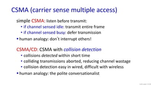
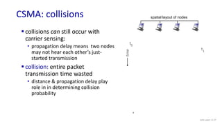
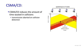
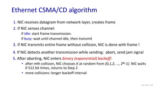
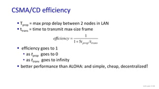
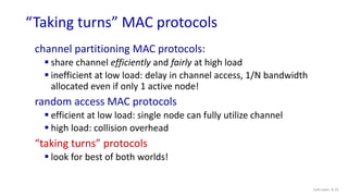
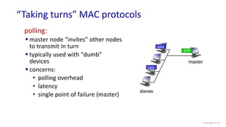
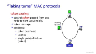
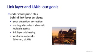
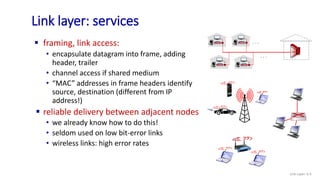
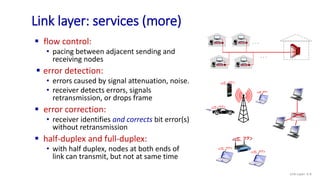
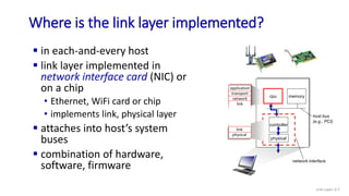
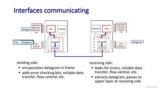
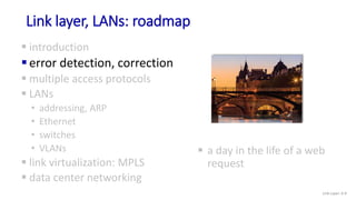
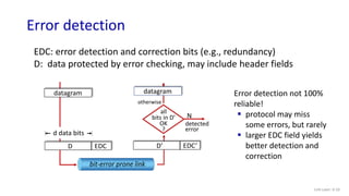
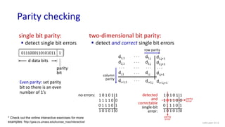
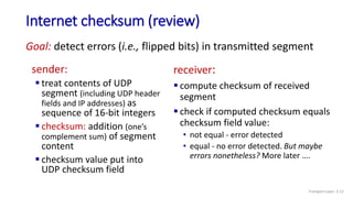
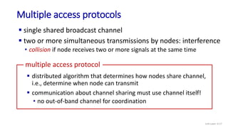
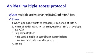
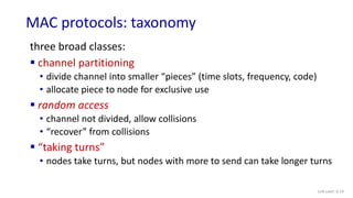
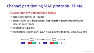
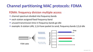
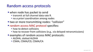
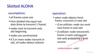
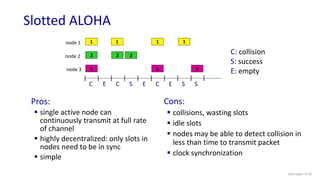
The document discusses principles of link layer services including error detection, correction, and sharing a broadcast channel through multiple access protocols. It provides an overview of topics like link layer addressing, local area networks including Ethernet and VLANs. Specific link layer services covered are error detection using techniques like parity checking and cyclic redundancy check (CRC). The document also distinguishes between point-to-point and broadcast links, and describes multiple access protocols for shared broadcast channels including TDMA, FDMA, and random access protocols like slotted ALOHA and CSMA.
![Link Layer: 6-14
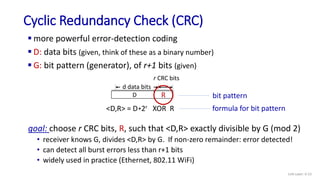
Cyclic Redundancy Check (CRC): example
We want:
D.2r XOR R = nG
* Check out the online interactive exercises for more examples: http://gaia.cs.umass.edu/kurose_ross/interactive/
D.2r
G
R = remainder [ ]
or equivalently:
D.2r = nG XOR R
or equivalently:
if we divide D.2r by G, want
remainder R to satisfy:
1 0 0 1
1 0 1 0
1 0 1
0 0 0
1 0 0 1
1 0 0 1
1 0 0 1
0 0 0
1 1 0
1 1 0 0
1 0 1 0
0 1 1
0 1 1
D
R
1 0 0 1
G
0 0 0
1 0 1 1 1 0
2r
*
1 0 1](https://image.slidesharecdn.com/lecture25linklayer-errordetectionandmultipleaccess-221225134931-6c96e2ea/85/Lecture-25-Link-Layer-Error-detection-and-Multiple-Access-pptx-14-320.jpg)
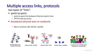
![Pure ALOHA
Link Layer: 6-25
unslotted Aloha: simpler, no synchronization
• when frame first arrives: transmit immediately
collision probability increases with no synchronization:
• frame sent at t0 collides with other frames sent in [t0-1,t0+1]
t0 + 1
t0 - 1 t0
will overlap
with end of
i’s frame
will overlap
with start of
i’s frame
pure Aloha efficiency: 18% !](https://image.slidesharecdn.com/lecture25linklayer-errordetectionandmultipleaccess-221225134931-6c96e2ea/85/Lecture-25-Link-Layer-Error-detection-and-Multiple-Access-pptx-25-320.jpg)