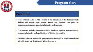
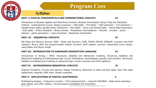
This document outlines the syllabus for a course on digital electronics. It includes:
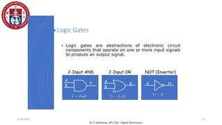
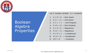
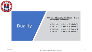
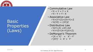
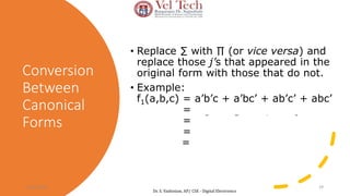
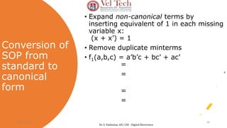
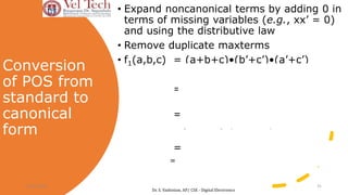
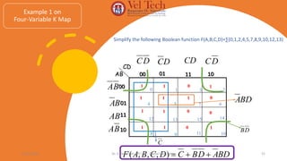
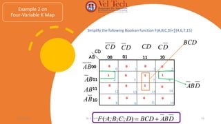
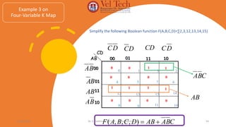
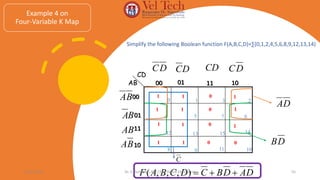
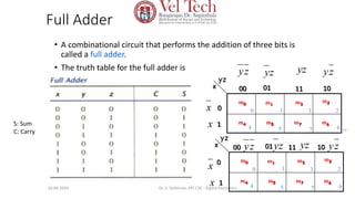
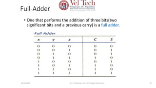
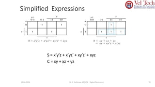
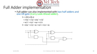
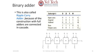
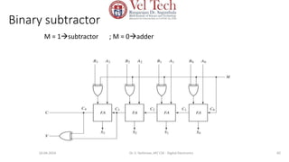
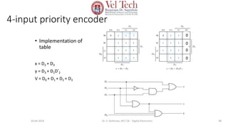
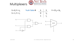
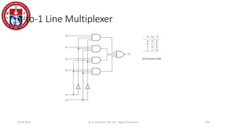
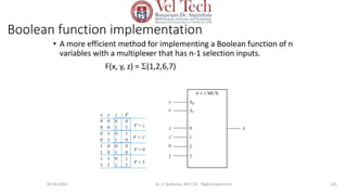
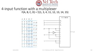
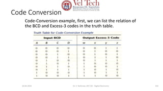
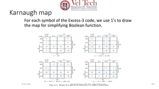
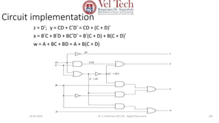
1) An introduction to Boolean algebra and switching functions, as well as combinational logic circuits like adders, subtractors, decoders, and multiplexers.
2) Sequential circuits like flip flops, counters, and shift registers.
3) Hardware description languages like Verilog and VHDL for designing digital circuits.
4) Asynchronous sequential circuits and their analysis.
5) Applications of digital electronics in areas like displays, frequency counters, and analog-to-digital converters.
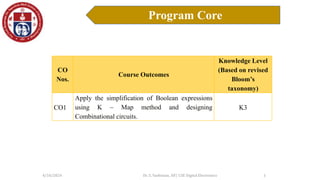
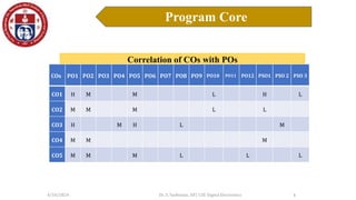
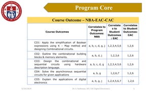
Recommended textbooks, references, and online resources are also provided, along with course outcomes correlated to program outcomes from NBA