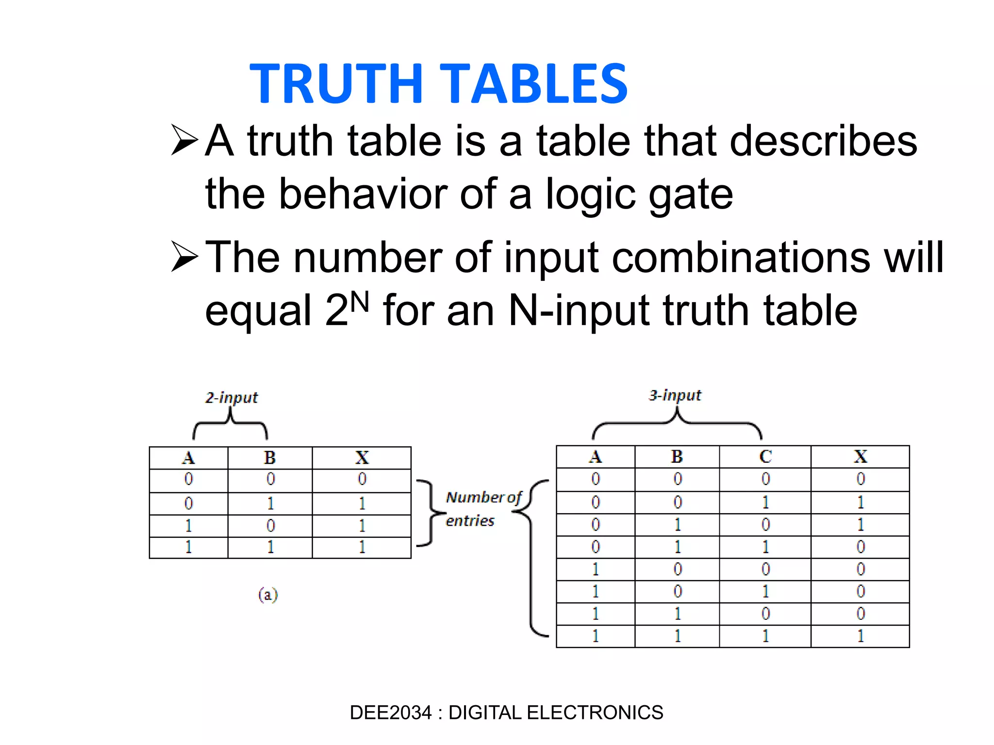
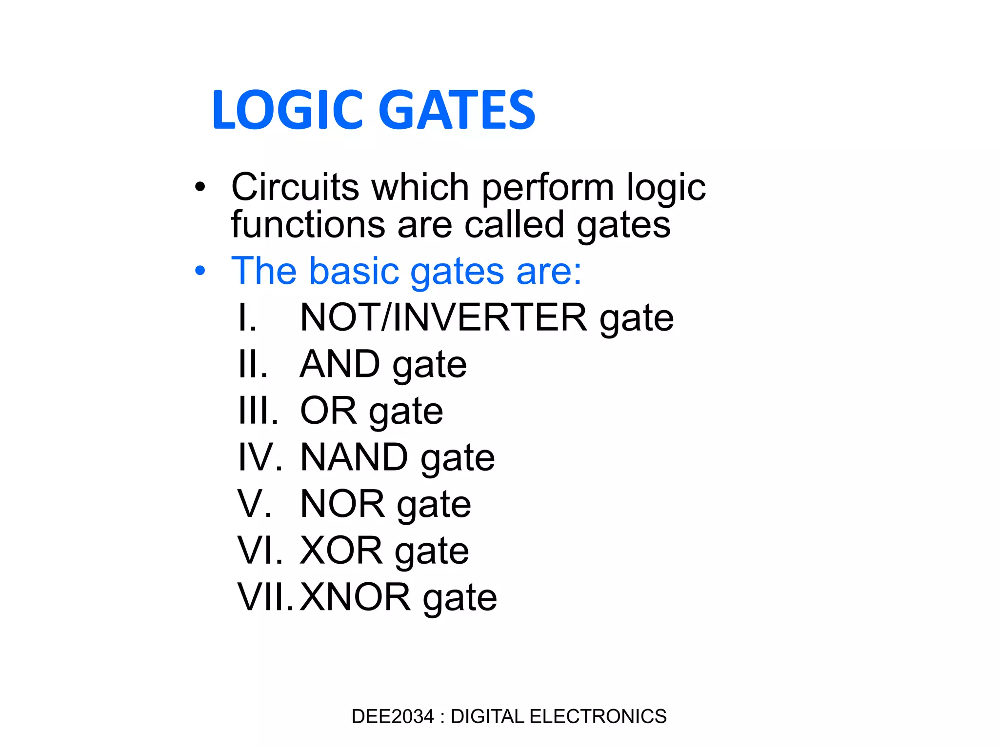
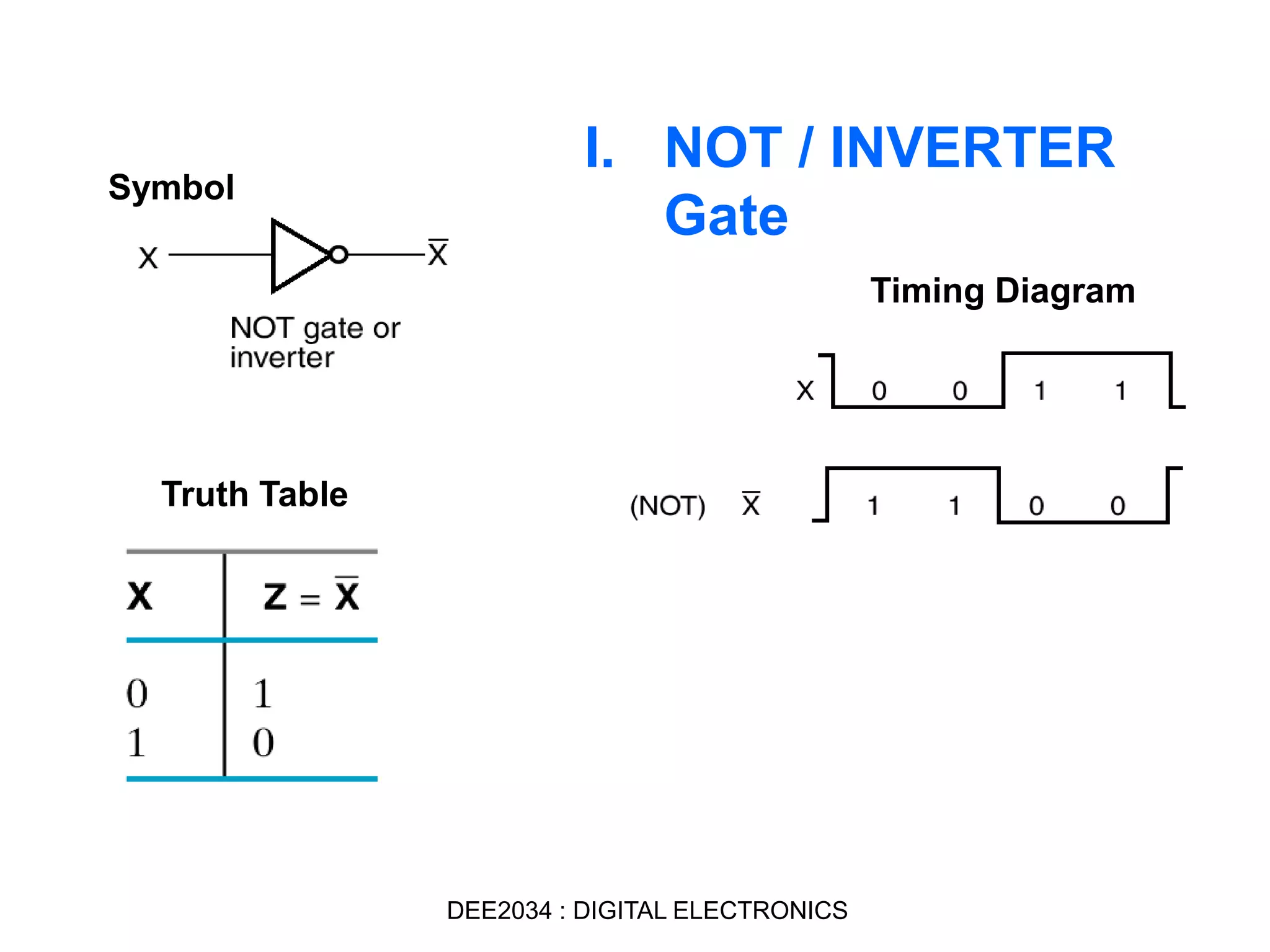
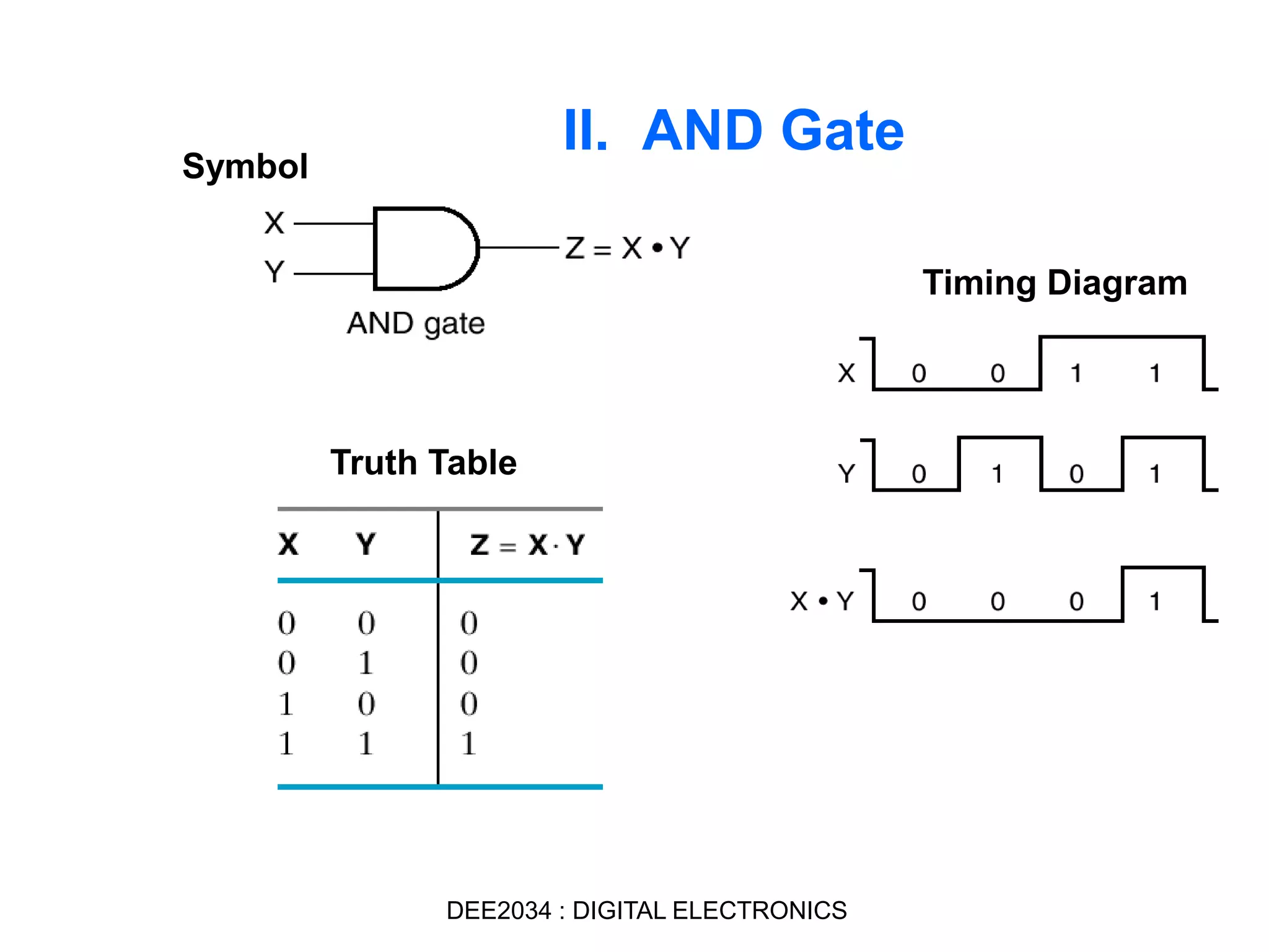
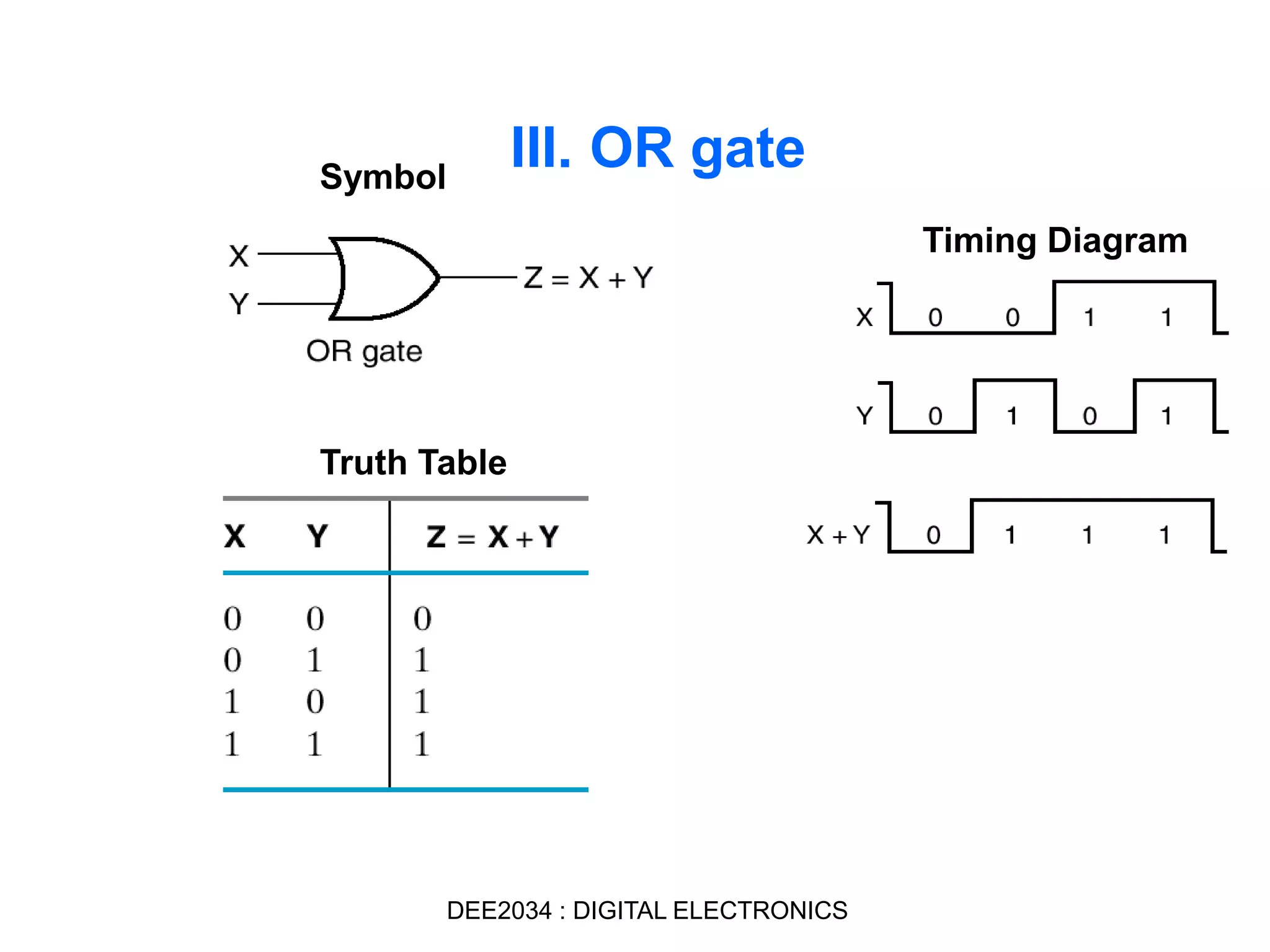
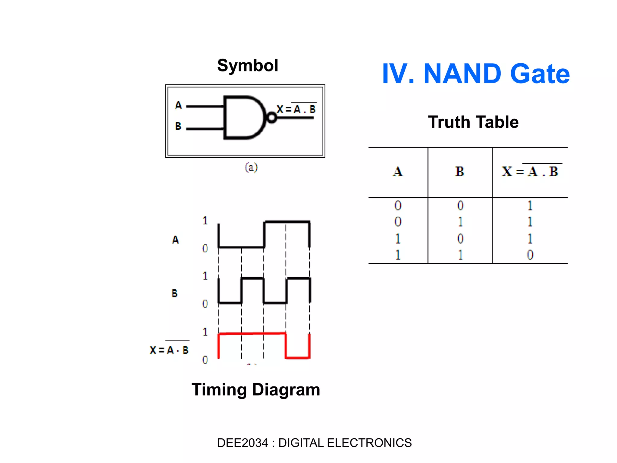
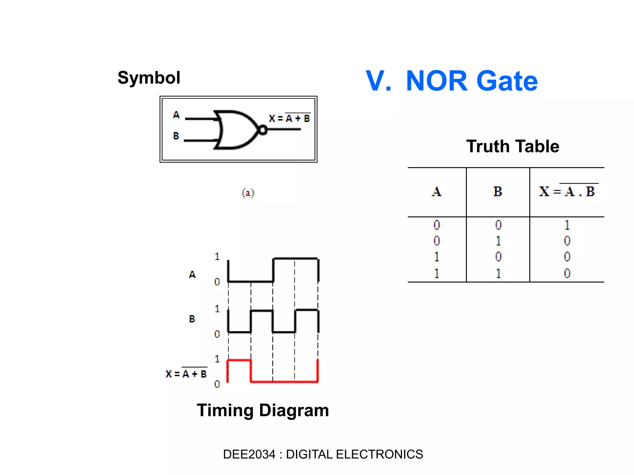
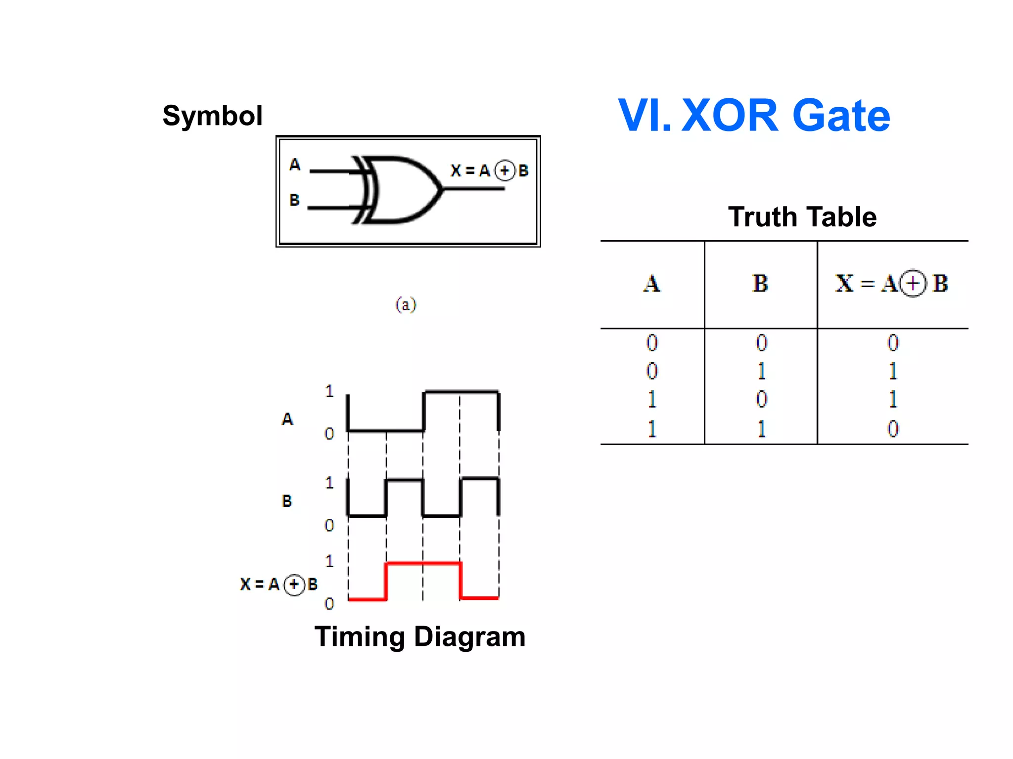
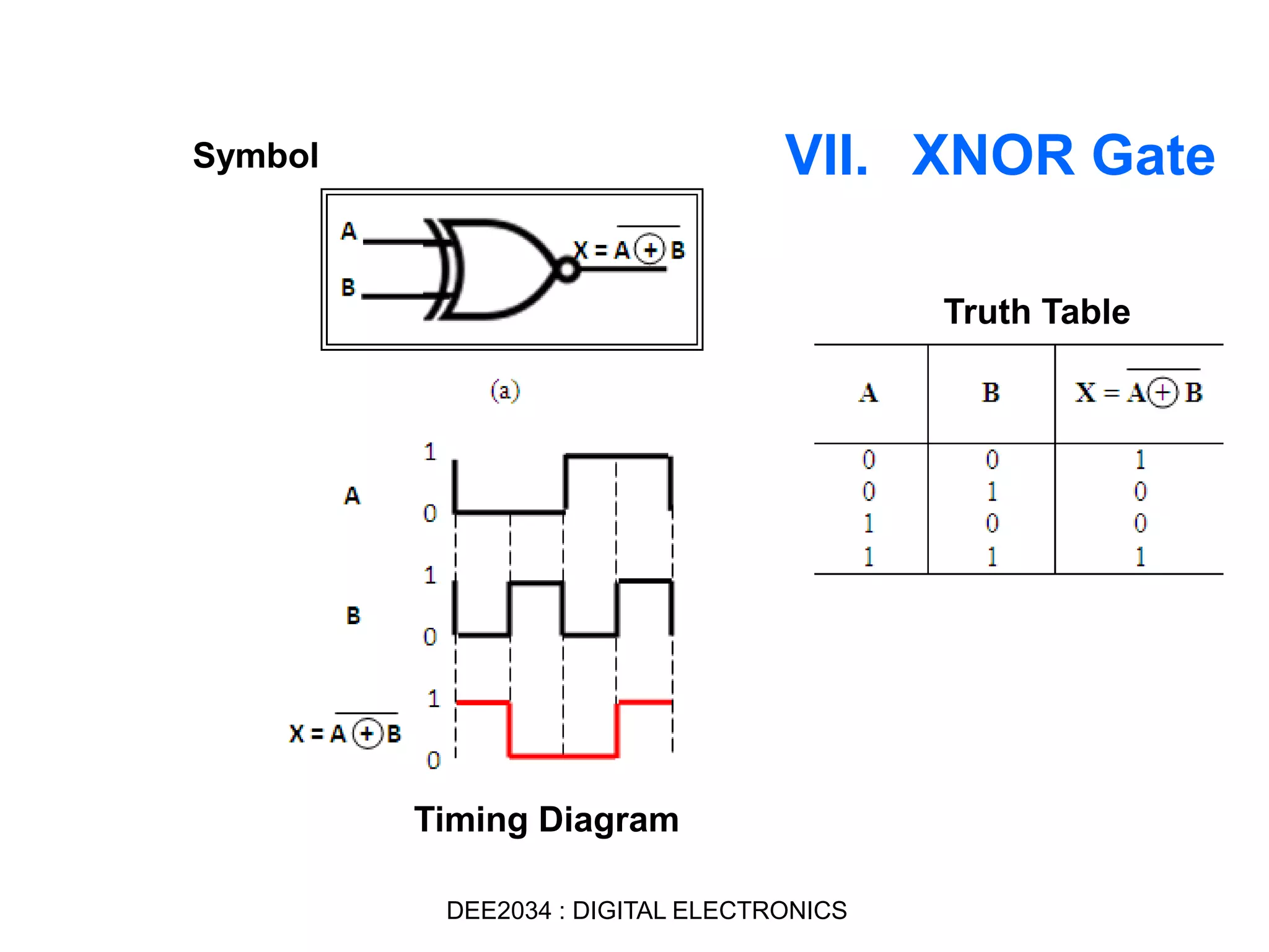
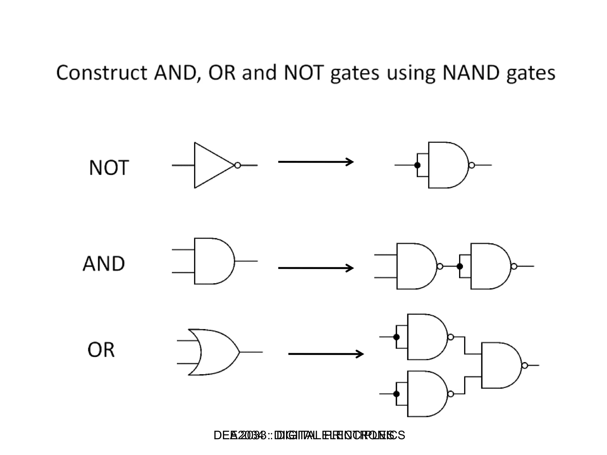
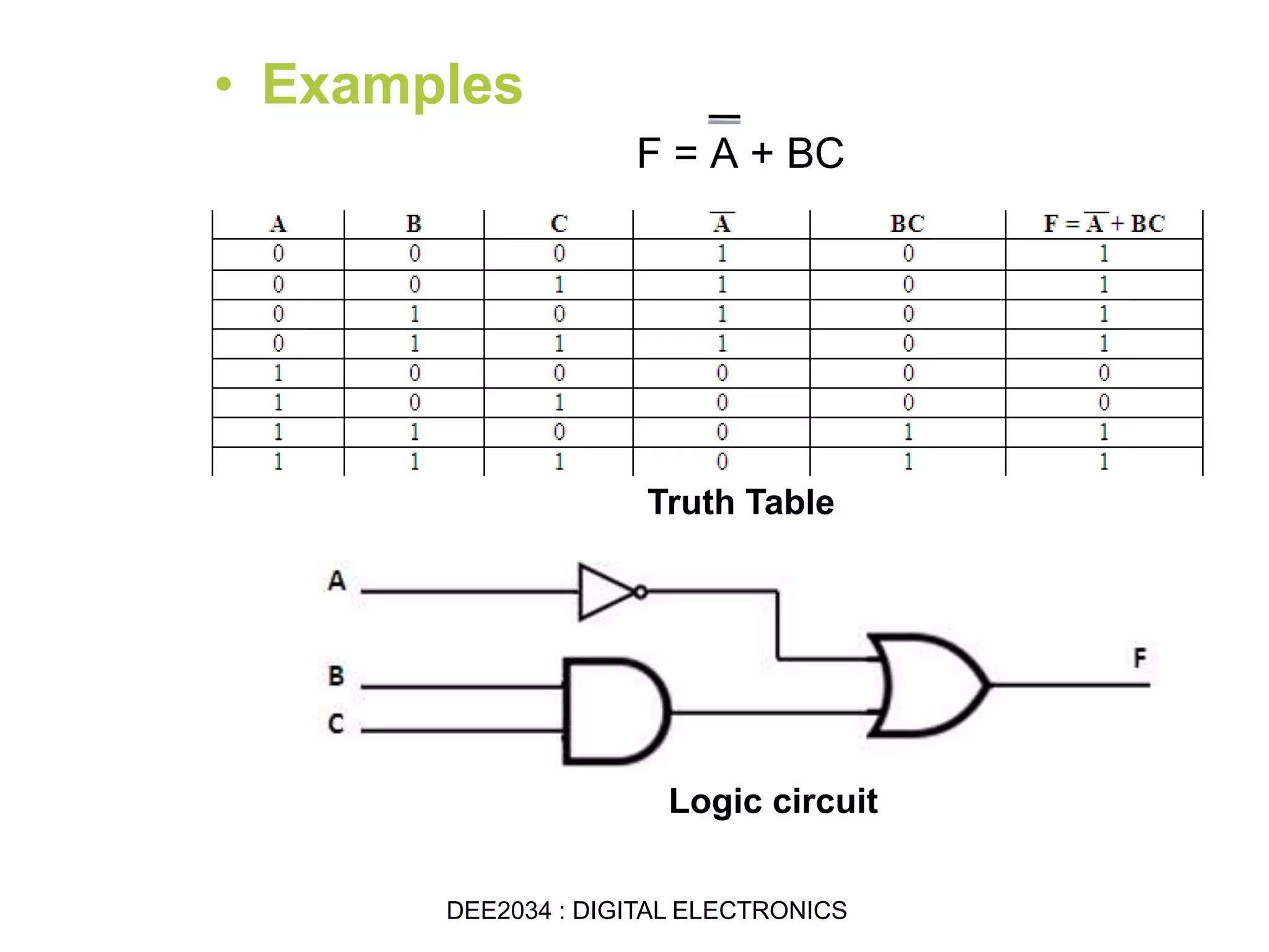
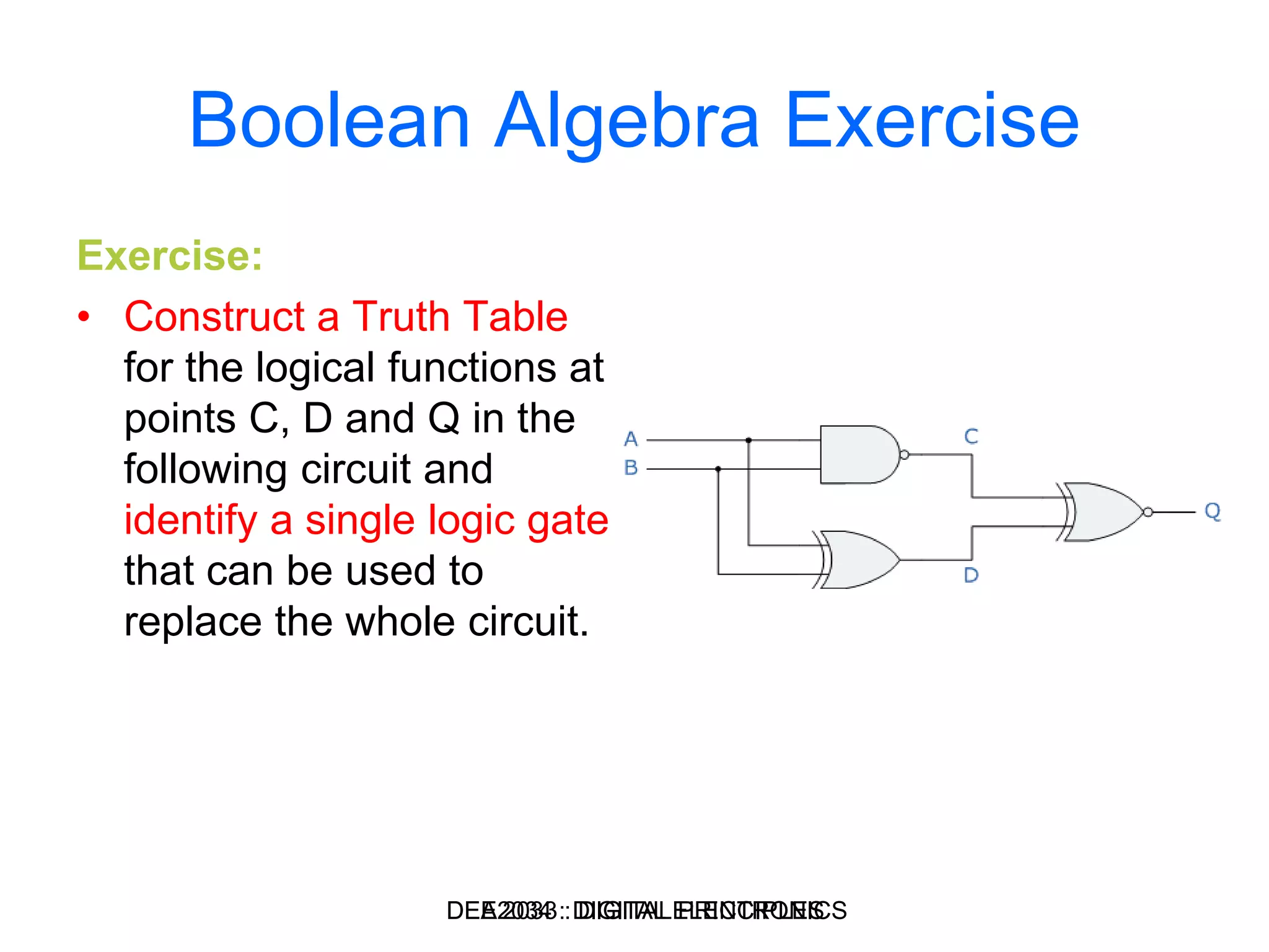
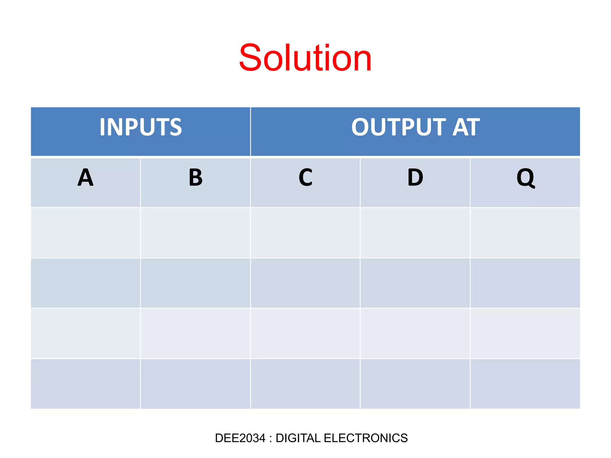
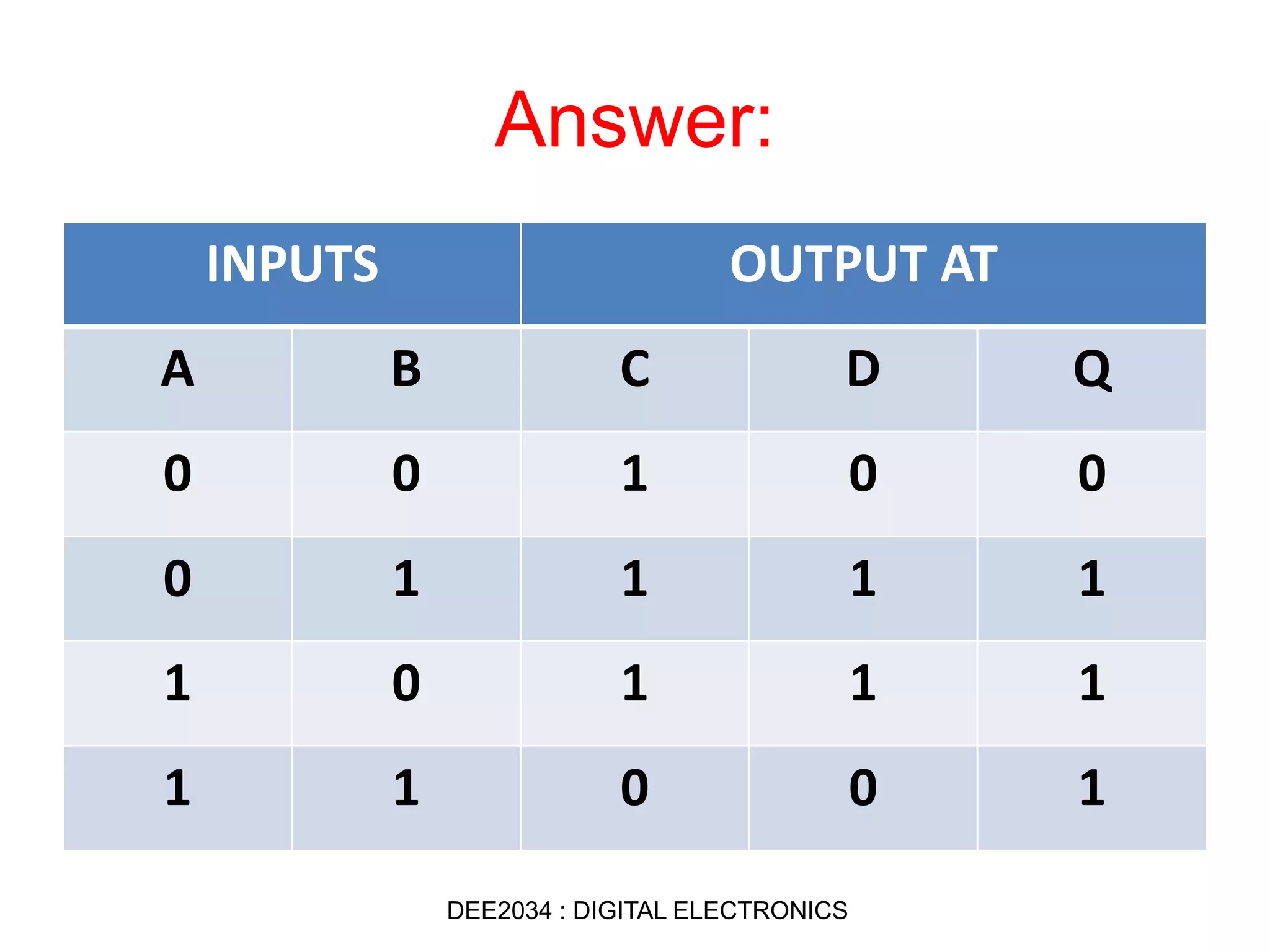
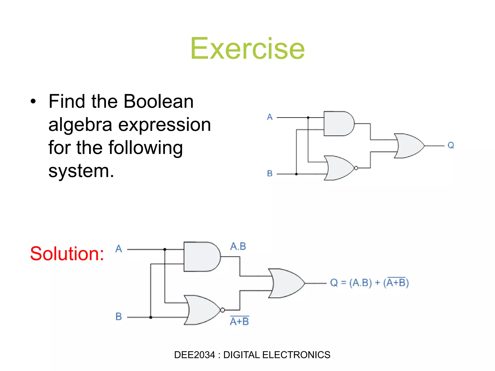
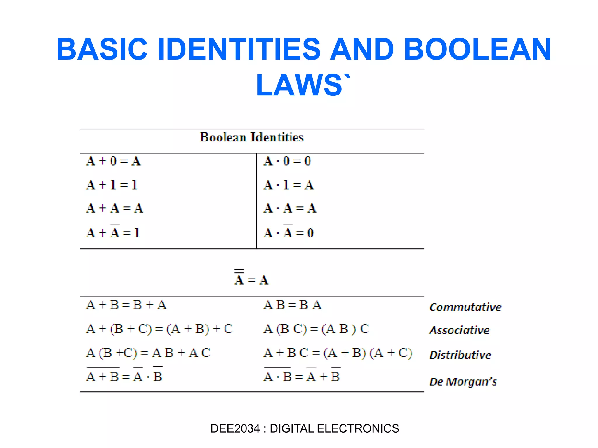
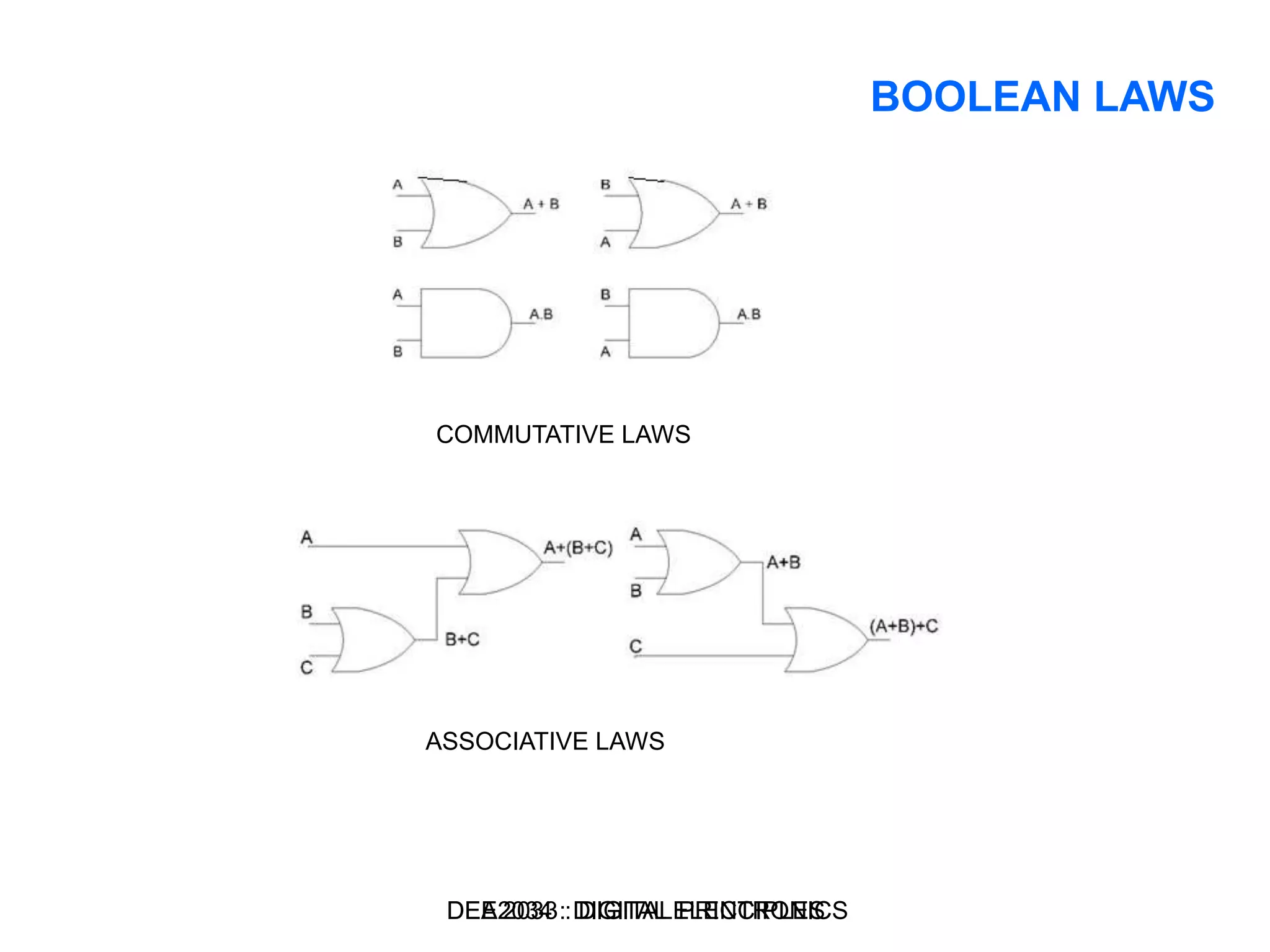
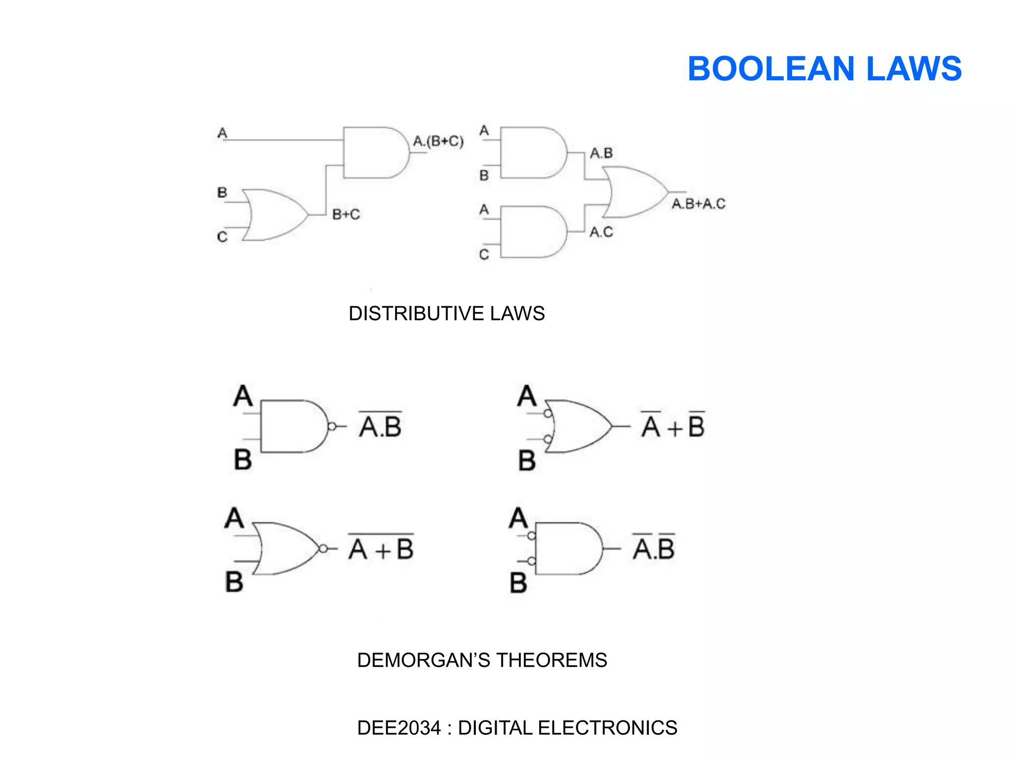
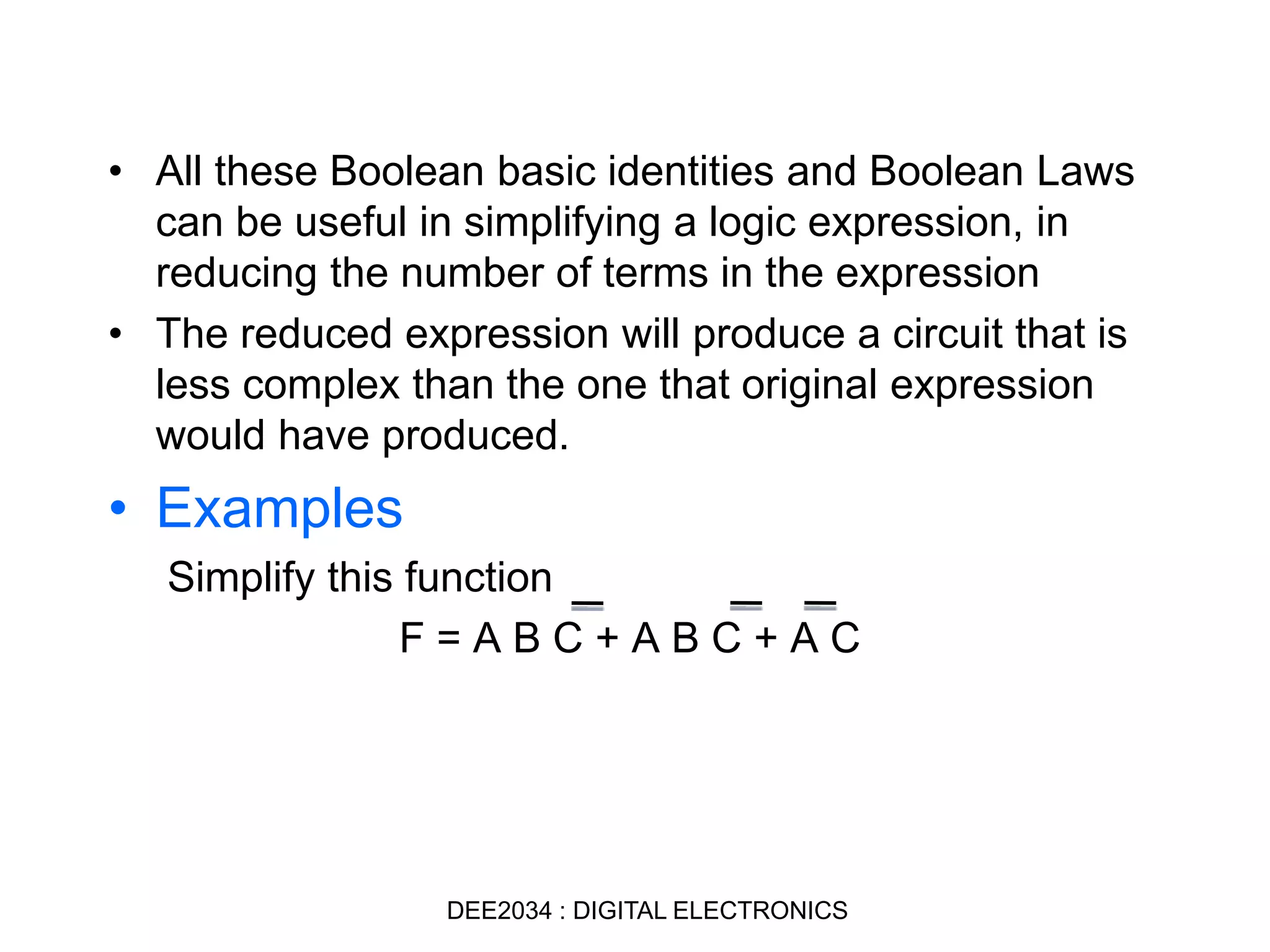
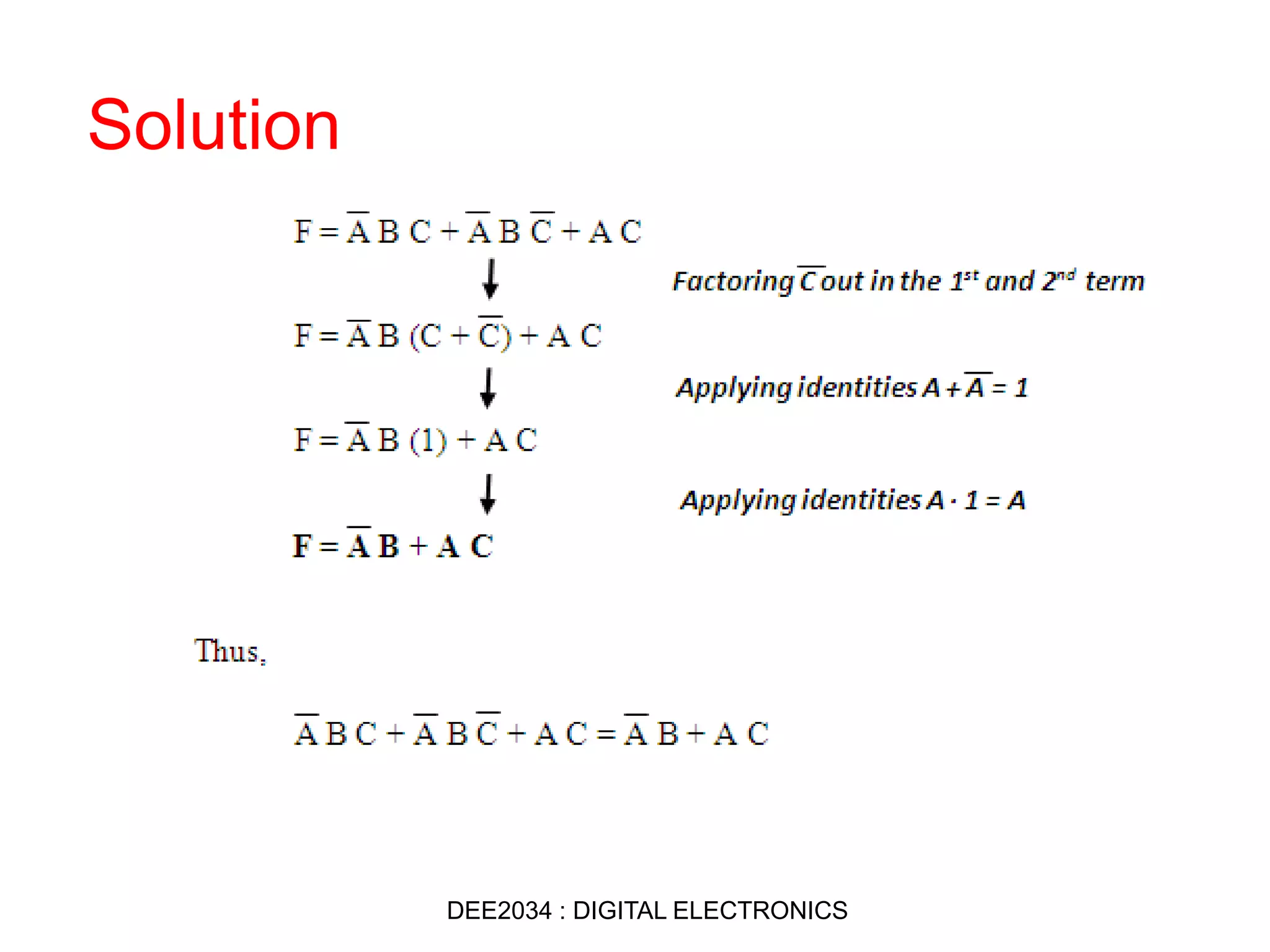
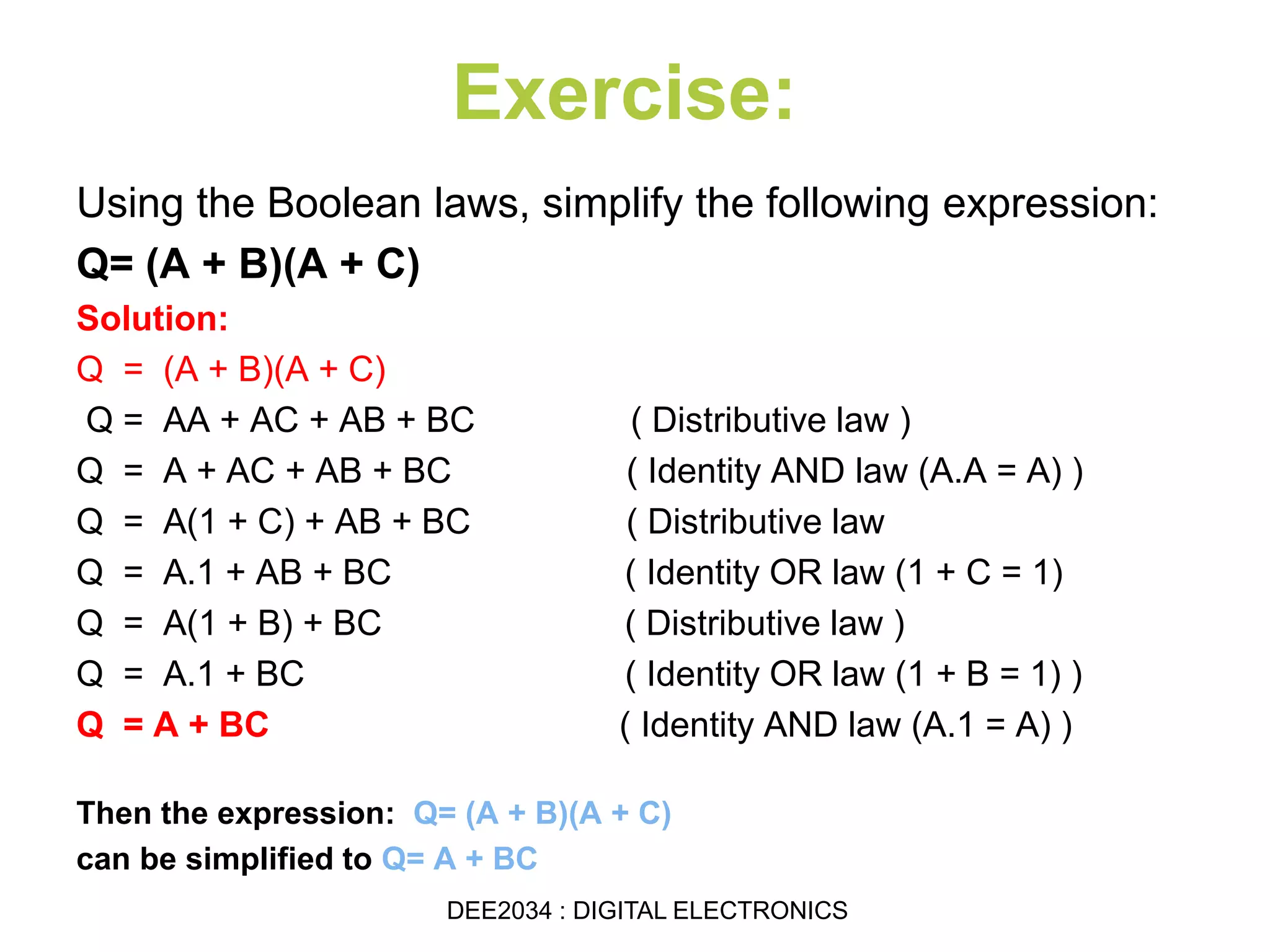
DEE2034 : DIGITAL ELECTRONICS
CHAPTER 2 : BOOLEAN
OPERATIONS by : Siti Sabariah Salihin
Electrical Engineering Department
sabariah@psa.edu.my
Programme Learning Outcomes, PLO
Upon completion of the programme, graduates should be able to:
• PLO 1 : Apply knowledge of mathematics, scince and engineering
fundamentals to well defined electrical and electronic engineering
procedures and practices
Course Learning Outcomes, CLO
• CLO 1 : Illustrate the knowledge of digital number systems,codes
and ligic operations correctly
• CLO 2 : Simplify and design combinational and sequential logic
circuits by using the Boolean Algebra and the Karnaugh Maps.
CHAPTER 2 : BOOLEAN OPERATIONS
EE 202 : DIGITAL ELECTRONICS
DEE2034 : DIGITAL ELECTRONICS
Upon completion of this Topic 2
student should be able to:
2.1 Know the symbols,operations and functions of logic gates.
2.1.1 Draw the symbols, operations and
functions of logic gates.
2.1.2 Explain the Function of Logic gates using Truth
Table.
2.1.3 Construct AND, OR and NOT gates using only
NAND gates.
2.2 Know the basic concepts of Boolean Algebra and use them in
Logic circuits analysis and design.
2.2.1 Construct the basic concepts of Boolean Algebra
and use them in logic circuits analysis and design.
2.2.2 State the Boolean Laws.
2.2.3 Develop logic expressions from the truth table from
the form of SOP and POS
2.2.4 Simplify combinatinal Logic circuits using Boolean
Laws and Karnaugh Map
DEE2034 : DIGITAL ELECTRONICS
TRUTH TABLES
A truth table is a table that describes
the behavior of a logic gate
The number of input combinations will
equal 2N for an N-input truth table
4DEE2034 : DIGITAL ELECTRONICS
• Circuits which perform logic
functions are called gates
• The basic gates are:
I. NOT/INVERTER gate
II. AND gate
III. OR gate
IV. NAND gate
V. NOR gate
VI. XOR gate
VII.XNOR gate
LOGIC GATES
DEE2034 : DIGITAL ELECTRONICS
I. NOT / INVERTER
Gate
Symbol
Truth Table
Timing Diagram
DEE2034 : DIGITAL ELECTRONICS
II. AND Gate
Symbol
Truth Table
Timing Diagram
DEE2034 : DIGITAL ELECTRONICS
III. OR gateSymbol
Truth Table
Timing Diagram
DEE2034 : DIGITAL ELECTRONICS
IV. NAND GateSymbol
Truth Table
Timing Diagram
DEE2034 : DIGITAL ELECTRONICS
V. NOR GateSymbol
Truth Table
Timing Diagram
DEE2034 : DIGITAL ELECTRONICS
VI. XOR GateSymbol
Truth Table
Timing Diagram
VII. XNOR GateSymbol
Truth Table
Timing Diagram
DEE2034 : DIGITAL ELECTRONICS
DEA 2033 : DIGITAL PRINCIPLESDEE2034 : DIGITAL ELECTRONICS
BOOLEAN ALGEBRA
• The Boolean algebra is an algebra dealing
with binary variables and logic operation
• The variables are designated by:
I. Letters of the alphabet
II. Three basic logic operations AND,
OR and NOT
DEE2034 : DIGITAL ELECTRONICS
• A Boolean function can be represented by using
truth table. A truth table for a function is a list of
all combinations of 1’s and 0’s that can be
assigned to the binary variable and a list that
shows the value of the function for each binary
combination
• A Boolean expression also can be transformed
into a circuit diagram composed of logic gates
that implements the function
BOOLEAN ALGEBRA
DEE2034 : DIGITAL ELECTRONICS
• Examples
F = A + BC
Truth Table
Logic circuit
DEE2034 : DIGITAL ELECTRONICS
Boolean Algebra Exercise
Exercise:
• Construct a Truth Table
for the logical functions at
points C, D and Q in the
following circuit and
identify a single logic gate
that can be used to
replace the whole circuit.
DEA 2033 : DIGITAL PRINCIPLESDEE2034 : DIGITAL ELECTRONICS
Solution
INPUTS OUTPUT AT
A B C D Q
DEE2034 : DIGITAL ELECTRONICS
Answer:
INPUTS OUTPUT AT
A B C D Q
0 0 1 0 0
0 1 1 1 1
1 0 1 1 1
1 1 0 0 1
DEE2034 : DIGITAL ELECTRONICS
Exercise
• Find the Boolean
algebra expression
for the following
system.
Solution:
DEE2034 : DIGITAL ELECTRONICS
BASIC IDENTITIES AND BOOLEAN
LAWS`
DEE2034 : DIGITAL ELECTRONICS
COMMUTATIVE LAWS
ASSOCIATIVE LAWS
BOOLEAN LAWS
DEA 2033 : DIGITAL PRINCIPLESDEE2034 : DIGITAL ELECTRONICS
DISTRIBUTIVE LAWS
DEMORGAN’S THEOREMS
BOOLEAN LAWS
DEE2034 : DIGITAL ELECTRONICS
• All these Boolean basic identities and Boolean Laws
can be useful in simplifying a logic expression, in
reducing the number of terms in the expression
• The reduced expression will produce a circuit that is
less complex than the one that original expression
would have produced.
• Examples
Simplify this function
F = A B C + A B C + A C
DEE2034 : DIGITAL ELECTRONICS
Solution
DEE2034 : DIGITAL ELECTRONICS
Exercise:
Using the Boolean laws, simplify the following expression:
Q= (A + B)(A + C)
Solution:
Q = (A + B)(A + C)
Q = AA + AC + AB + BC ( Distributive law )
Q = A + AC + AB + BC ( Identity AND law (A.A = A) )
Q = A(1 + C) + AB + BC ( Distributive law
Q = A.1 + AB + BC ( Identity OR law (1 + C = 1)
Q = A(1 + B) + BC ( Distributive law )
Q = A.1 + BC ( Identity OR law (1 + B = 1) )
Q = A + BC ( Identity AND law (A.1 = A) )
Then the expression: Q= (A + B)(A + C)
can be simplified to Q= A + BC
DEE2034 : DIGITAL ELECTRONICS
continue chapter 2 Part B
1. "Digital Systems Principles And Application"
Sixth Editon, Ronald J. Tocci.
2. "Digital Systems Fundamentals"
P.W Chandana Prasad, Lau Siong Hoe,
Dr. Ashutosh Kumar Singh, Muhammad Suryanata.
REFERENCES:
Download Tutorials Chapter 2: Boolean Operations
@ http://www.portal.cidos.edu.my
DEE2034 : DIGITAL ELECTRONICS

Dee2034 chapter 2 boolean algebra part a

  • 1.
    DEE2034 : DIGITALELECTRONICS CHAPTER 2 : BOOLEAN OPERATIONS by : Siti Sabariah Salihin Electrical Engineering Department sabariah@psa.edu.my
  • 2.
    Programme Learning Outcomes,PLO Upon completion of the programme, graduates should be able to: • PLO 1 : Apply knowledge of mathematics, scince and engineering fundamentals to well defined electrical and electronic engineering procedures and practices Course Learning Outcomes, CLO • CLO 1 : Illustrate the knowledge of digital number systems,codes and ligic operations correctly • CLO 2 : Simplify and design combinational and sequential logic circuits by using the Boolean Algebra and the Karnaugh Maps. CHAPTER 2 : BOOLEAN OPERATIONS EE 202 : DIGITAL ELECTRONICS DEE2034 : DIGITAL ELECTRONICS
  • 3.
    Upon completion ofthis Topic 2 student should be able to: 2.1 Know the symbols,operations and functions of logic gates. 2.1.1 Draw the symbols, operations and functions of logic gates. 2.1.2 Explain the Function of Logic gates using Truth Table. 2.1.3 Construct AND, OR and NOT gates using only NAND gates. 2.2 Know the basic concepts of Boolean Algebra and use them in Logic circuits analysis and design. 2.2.1 Construct the basic concepts of Boolean Algebra and use them in logic circuits analysis and design. 2.2.2 State the Boolean Laws. 2.2.3 Develop logic expressions from the truth table from the form of SOP and POS 2.2.4 Simplify combinatinal Logic circuits using Boolean Laws and Karnaugh Map DEE2034 : DIGITAL ELECTRONICS
  • 4.
    TRUTH TABLES A truthtable is a table that describes the behavior of a logic gate The number of input combinations will equal 2N for an N-input truth table 4DEE2034 : DIGITAL ELECTRONICS
  • 5.
    • Circuits whichperform logic functions are called gates • The basic gates are: I. NOT/INVERTER gate II. AND gate III. OR gate IV. NAND gate V. NOR gate VI. XOR gate VII.XNOR gate LOGIC GATES DEE2034 : DIGITAL ELECTRONICS
  • 6.
    I. NOT /INVERTER Gate Symbol Truth Table Timing Diagram DEE2034 : DIGITAL ELECTRONICS
  • 7.
    II. AND Gate Symbol TruthTable Timing Diagram DEE2034 : DIGITAL ELECTRONICS
  • 8.
    III. OR gateSymbol TruthTable Timing Diagram DEE2034 : DIGITAL ELECTRONICS
  • 9.
    IV. NAND GateSymbol TruthTable Timing Diagram DEE2034 : DIGITAL ELECTRONICS
  • 10.
    V. NOR GateSymbol TruthTable Timing Diagram DEE2034 : DIGITAL ELECTRONICS
  • 11.
    VI. XOR GateSymbol TruthTable Timing Diagram
  • 12.
    VII. XNOR GateSymbol TruthTable Timing Diagram DEE2034 : DIGITAL ELECTRONICS
  • 13.
    DEA 2033 :DIGITAL PRINCIPLESDEE2034 : DIGITAL ELECTRONICS
  • 14.
    BOOLEAN ALGEBRA • TheBoolean algebra is an algebra dealing with binary variables and logic operation • The variables are designated by: I. Letters of the alphabet II. Three basic logic operations AND, OR and NOT DEE2034 : DIGITAL ELECTRONICS
  • 15.
    • A Booleanfunction can be represented by using truth table. A truth table for a function is a list of all combinations of 1’s and 0’s that can be assigned to the binary variable and a list that shows the value of the function for each binary combination • A Boolean expression also can be transformed into a circuit diagram composed of logic gates that implements the function BOOLEAN ALGEBRA DEE2034 : DIGITAL ELECTRONICS
  • 16.
    • Examples F =A + BC Truth Table Logic circuit DEE2034 : DIGITAL ELECTRONICS
  • 17.
    Boolean Algebra Exercise Exercise: •Construct a Truth Table for the logical functions at points C, D and Q in the following circuit and identify a single logic gate that can be used to replace the whole circuit. DEA 2033 : DIGITAL PRINCIPLESDEE2034 : DIGITAL ELECTRONICS
  • 18.
    Solution INPUTS OUTPUT AT AB C D Q DEE2034 : DIGITAL ELECTRONICS
  • 19.
    Answer: INPUTS OUTPUT AT AB C D Q 0 0 1 0 0 0 1 1 1 1 1 0 1 1 1 1 1 0 0 1 DEE2034 : DIGITAL ELECTRONICS
  • 20.
    Exercise • Find theBoolean algebra expression for the following system. Solution: DEE2034 : DIGITAL ELECTRONICS
  • 21.
    BASIC IDENTITIES ANDBOOLEAN LAWS` DEE2034 : DIGITAL ELECTRONICS
  • 22.
    COMMUTATIVE LAWS ASSOCIATIVE LAWS BOOLEANLAWS DEA 2033 : DIGITAL PRINCIPLESDEE2034 : DIGITAL ELECTRONICS
  • 23.
    DISTRIBUTIVE LAWS DEMORGAN’S THEOREMS BOOLEANLAWS DEE2034 : DIGITAL ELECTRONICS
  • 24.
    • All theseBoolean basic identities and Boolean Laws can be useful in simplifying a logic expression, in reducing the number of terms in the expression • The reduced expression will produce a circuit that is less complex than the one that original expression would have produced. • Examples Simplify this function F = A B C + A B C + A C DEE2034 : DIGITAL ELECTRONICS
  • 25.
  • 26.
    Exercise: Using the Booleanlaws, simplify the following expression: Q= (A + B)(A + C) Solution: Q = (A + B)(A + C) Q = AA + AC + AB + BC ( Distributive law ) Q = A + AC + AB + BC ( Identity AND law (A.A = A) ) Q = A(1 + C) + AB + BC ( Distributive law Q = A.1 + AB + BC ( Identity OR law (1 + C = 1) Q = A(1 + B) + BC ( Distributive law ) Q = A.1 + BC ( Identity OR law (1 + B = 1) ) Q = A + BC ( Identity AND law (A.1 = A) ) Then the expression: Q= (A + B)(A + C) can be simplified to Q= A + BC DEE2034 : DIGITAL ELECTRONICS
  • 27.
    continue chapter 2Part B 1. "Digital Systems Principles And Application" Sixth Editon, Ronald J. Tocci. 2. "Digital Systems Fundamentals" P.W Chandana Prasad, Lau Siong Hoe, Dr. Ashutosh Kumar Singh, Muhammad Suryanata. REFERENCES: Download Tutorials Chapter 2: Boolean Operations @ http://www.portal.cidos.edu.my DEE2034 : DIGITAL ELECTRONICS