Frequency-Shift Keying, also known as FSK is a type of digital frequency modulation. It is also often called as binary frequency shift keying or BFSK
Similar to analog FM, it is a constant-amplitude angle modulation.
This presentation will discuss the concepts behind FSK
Frequency-Shift Keying, also known as FSK is a type of digital frequency modulation. It is also often called as binary frequency shift keying or BFSK
Similar to analog FM, it is a constant-amplitude angle modulation.
This presentation will discuss the concepts behind FSK
Salient Features:
The magnitude response is nearly constant(equal to 1) at lower frequencies
There are no ripples in passband and stop band
The maximum gain occurs at Ω=0 and it is H(Ω)=1
The magnitude response is monotonically decreasing
As the order of the filter ‘N’ increases, the response of the filter is more close to the ideal response
Details: https://electronicsembeddedworld.blogspot.com/2018/06/performance-management-mcq.html
FM demodulation involves changing the frequency variations in a signal into amplitude variations at baseband, e.g. audio. There are several techniques and circuits that can be used each with its own advantages and disadvantages.
In any radio that is designed to receive frequency modulated signals there is some form of FM demodulator or detector. This circuit takes in frequency modulated RF signals and takes the modulation from the signal to output only the modulation that had been applied at the transmitter.
There are several types of FM detector / demodulator that can be used. Some types were more popular in the days when radios were made from discrete devices, but nowadays the PLL based detector and quadrature / coincidence detectors are the most widely used as they lend themselves to being incorporated into integrated circuits very easily...
In this video, I will explain what is QAM modulation and what is 16QAM.
QAM Stands for Quadrature Amplitude Modulation. QAM is both an analog and a digital modulation method. But here, we are only talking about QAM as a digital modulation.
Quadrature means that two carrier waves are being used, one sine wave and one cosine wave. These two waves are out of phase with each other by 90°, this is called quadrature.
At the receiving end, the sine and cosine wave can be decoded independently, this means that by using both a sine wave and a cosine wave, the communication channel's capacity is doubled comparing to using only one sine or one cosine wave. That is why quadrature is such a popular technique for digital modulation.
QAM modulation is a combination of Amplitude Shift Keying and Phase Shift Keying, both carrier wave is modulated by changing both its amplitude and phase. As shown in this 8QAM waveform, the top is the sine wave carrier, for bit 000, the sin wave has a phase shift of 0°, and an amplitude of 2. While for bit 110, the phase shift is 180°, and the amplitude now is 1. So both phase and amplitude are changed.
In 16QAM, the input binary data is combined into groups of 4 bits called QUADBITS.
As shown in this picture, the I and I' bits are sent to the sine wave modulation path, and the Q and Q' bits are sent to the cosine wave path. Since the bits are split and sent in parallel, so the symbol rate has been reduced to a quarter of the input binary bit rate. If the input binary data rate is 100 Gbps, then the symbol rate is reduced to only 25 Gbaud/second. This is the reason why 16QAM is under hot research for 100Gbps fiber optic communication.
The I and Q bits control the carrier wave's phase shift, if the bit is 0, then the phase shift is 180°, if the bit is 1, then the phase shift is 0°.
The I' and Q' bits control the carrier wave's amplitude, if bit is 0, then the amplitude is 0.22 volt, if the bit is 1, then the amplitude is 0.821 volt.
So each pair of bits has 4 different outputs. Then they are added up at the linear summer. 4X4 is 16, so there is a total of 16 different combinations at the output, that is why this is called 16QAM.
This illustration shows an example of how the QUADBIT 0000 is modulated onto the carrier waves.
Here I and I' is 00, so the output is -0.22 Volt at the 2-to-4-level converter, when timed with the sine wave carrier, we get -0.22sin(2πfct), here fc is the carrier wave's frequency. QQ' is also 00, so the other carrier wave output is -0.22cos(2πfct).
Here is the proof that quadbit 0000 is modulated as a sine wave with an amplitude of 0.311volt and a phase shift of -135°. You can now pause for a moment to study the proof.
This list shows the 16QAM modulation output with different amplitude and phase change for all 16 quadbits. On the right side is the constellation diagram which shows the positions of these quadbits on a I-Q diagram.
You can visit FO4SALE.com f
This presentation covers:
Some basic definitions & concepts of digital communication
What is Phase Shift Keying(PSK) ?
Binary Phase Shift Keying – BPSK
BPSK transmitter & receiver
Advantages & Disadvantages of BPSK
Pi/4 – QPSK
Pi/4 – QPSK transmitter & receiver
Advantages of Pi/4- QPSK
This presentation contain each and every single information on the topic.
If you like it do follow and like my presentation.
It would be worth my efforts.
Comparative Study and Performance Analysis of different Modulation Techniques...Souvik Das
A comparative study and performance analysis of different modulation
techniques which shows graphically and comparative results Channel Noise
with Bit Error Rate of ASK, FSK, PSK and QPSK.
three level diode clamp inverter. that converts any type of DC ( rectified, PV cell, battery etc.) to AC supply. we made by mosfet and ardiuno . in this ppt we present the Simulink model of a three-level inverter and the hardware presentation of the inverter.
Design of Two CMOS Differential Amplifiersbastrikov
High performance, 0.6u process CMOS differential amplifiers were designed in Cadence. Design specifications included differential gain, 3-db bandwidth, output swing, input common mode range, phase margin, total static power consumption, slew rate, and common mode rejection ratio.
This slide describe the techniques of digital modulation and Bandwidth Efficiency:
The first null bandwidth of M-ary PSK signals decrease as M increases while Rb is held constant.
Therefore, as the value of M increases, the bandwidth efficiency also increases.
Sachpazis:Terzaghi Bearing Capacity Estimation in simple terms with Calculati...Dr.Costas Sachpazis
Terzaghi's soil bearing capacity theory, developed by Karl Terzaghi, is a fundamental principle in geotechnical engineering used to determine the bearing capacity of shallow foundations. This theory provides a method to calculate the ultimate bearing capacity of soil, which is the maximum load per unit area that the soil can support without undergoing shear failure. The Calculation HTML Code included.
CFD Simulation of By-pass Flow in a HRSG module by R&R Consult.pptxR&R Consult
CFD analysis is incredibly effective at solving mysteries and improving the performance of complex systems!
Here's a great example: At a large natural gas-fired power plant, where they use waste heat to generate steam and energy, they were puzzled that their boiler wasn't producing as much steam as expected.
R&R and Tetra Engineering Group Inc. were asked to solve the issue with reduced steam production.
An inspection had shown that a significant amount of hot flue gas was bypassing the boiler tubes, where the heat was supposed to be transferred.
R&R Consult conducted a CFD analysis, which revealed that 6.3% of the flue gas was bypassing the boiler tubes without transferring heat. The analysis also showed that the flue gas was instead being directed along the sides of the boiler and between the modules that were supposed to capture the heat. This was the cause of the reduced performance.
Based on our results, Tetra Engineering installed covering plates to reduce the bypass flow. This improved the boiler's performance and increased electricity production.
It is always satisfying when we can help solve complex challenges like this. Do your systems also need a check-up or optimization? Give us a call!
Work done in cooperation with James Malloy and David Moelling from Tetra Engineering.
More examples of our work https://www.r-r-consult.dk/en/cases-en/
Cosmetic shop management system project report.pdfKamal Acharya
Buying new cosmetic products is difficult. It can even be scary for those who have sensitive skin and are prone to skin trouble. The information needed to alleviate this problem is on the back of each product, but it's thought to interpret those ingredient lists unless you have a background in chemistry.
Instead of buying and hoping for the best, we can use data science to help us predict which products may be good fits for us. It includes various function programs to do the above mentioned tasks.
Data file handling has been effectively used in the program.
The automated cosmetic shop management system should deal with the automation of general workflow and administration process of the shop. The main processes of the system focus on customer's request where the system is able to search the most appropriate products and deliver it to the customers. It should help the employees to quickly identify the list of cosmetic product that have reached the minimum quantity and also keep a track of expired date for each cosmetic product. It should help the employees to find the rack number in which the product is placed.It is also Faster and more efficient way.
Hybrid optimization of pumped hydro system and solar- Engr. Abdul-Azeez.pdffxintegritypublishin
Advancements in technology unveil a myriad of electrical and electronic breakthroughs geared towards efficiently harnessing limited resources to meet human energy demands. The optimization of hybrid solar PV panels and pumped hydro energy supply systems plays a pivotal role in utilizing natural resources effectively. This initiative not only benefits humanity but also fosters environmental sustainability. The study investigated the design optimization of these hybrid systems, focusing on understanding solar radiation patterns, identifying geographical influences on solar radiation, formulating a mathematical model for system optimization, and determining the optimal configuration of PV panels and pumped hydro storage. Through a comparative analysis approach and eight weeks of data collection, the study addressed key research questions related to solar radiation patterns and optimal system design. The findings highlighted regions with heightened solar radiation levels, showcasing substantial potential for power generation and emphasizing the system's efficiency. Optimizing system design significantly boosted power generation, promoted renewable energy utilization, and enhanced energy storage capacity. The study underscored the benefits of optimizing hybrid solar PV panels and pumped hydro energy supply systems for sustainable energy usage. Optimizing the design of solar PV panels and pumped hydro energy supply systems as examined across diverse climatic conditions in a developing country, not only enhances power generation but also improves the integration of renewable energy sources and boosts energy storage capacities, particularly beneficial for less economically prosperous regions. Additionally, the study provides valuable insights for advancing energy research in economically viable areas. Recommendations included conducting site-specific assessments, utilizing advanced modeling tools, implementing regular maintenance protocols, and enhancing communication among system components.
Welcome to WIPAC Monthly the magazine brought to you by the LinkedIn Group Water Industry Process Automation & Control.
In this month's edition, along with this month's industry news to celebrate the 13 years since the group was created we have articles including
A case study of the used of Advanced Process Control at the Wastewater Treatment works at Lleida in Spain
A look back on an article on smart wastewater networks in order to see how the industry has measured up in the interim around the adoption of Digital Transformation in the Water Industry.
3. Noise in communication systems
• Thermal noise is described by a zero-mean white Gaussian random
process, n(t).
• Its PSD is flat, hence, it is called white noise.
Autocorrelation function
Probability density function
Power spectral density
73
4. Signal transmission through linear systems
Input Output
Linear system
–Deterministic signals:
–Random signals:
74
6. Bandwidth of signal
• Baseband versus bandpass:
• Bandwidth dilemma:
• Bandlimited signals are not realizable!
• Realizable signals have infinite bandwidth!
Baseband
signal
Bandpass
signal
Local oscillator
76
7. Bits per PCM Word
PCM word size
How many bits shall we assign to each analog sample?
p
l
p
p
L
pV
L
V
L
Vq
e
pVe
l
pp
pp
pp
pp
2
1
log
2
1
2
2
1
2
22
2
max
e: quantization error,
Vpp peak-to-peak voltage
q: quantization level
77
9. Bandwidth of signal …
• Different definition of bandwidth:
a)
b)
c)
Half-power bandwidth
Noise equivalent bandwidth
Null-to-null bandwidth
d) Fractional power containment bandwidth
e) Bounded power spectral density
f) Absolute bandwidth
(a)
(b)
(c)
(d)
(e)50dB
79
10. Spectral Efficiency
■ We can say that the Null-to-Null bandwidth is equal to 2/T. Where, T is
the width of the pulse.
■ In case of binary pulse we can only Transmit 1 bit per symbol (pulse).
In case of M-ary we can transmit log2(M).
■ Spectral efficiency is the number of bits transmitted per bandwidth
used. Thus, in case of binary pulses it is 1/(2/T). In case of M-ary it is
log2(M) /(2/T). We consider here NtoN Bandwidth
■ Binary pulses have less spectral efficiency as compared to M-ary.
However, the transmission of more bits per pulse will increase the
error probability. More bits per pulse means more erroneus bits.
80
14. What is modulation ?
■ Modulation = Adding information to a carrier signal
■ Digital to Analog Modulation
– process of changing one of the characteristic of an
analog signal (typically a cosine wave) based on the
information in a digital signal
■ The cosine wave on which the characteristics of the
information signal are modulated is called a carrier
signal
84
16. Signal characteristics that can
be modified
signal x(t) = A cos(2πft + Φ)
• A – amplitude
• f – frequency
• Φ – phase
• A- amplitude and phase together
86
17. 5.87
Amplitude Shift Keying (ASK)
■ ASK is implemented by changing the
amplitude of a carrier signal to reflect
amplitude levels in the digital signal.
■ For example: a digital “1” could not affect the
signal, whereas a digital “0” would, by making
it zero.
■ The line encoding will determine the values of
the analog waveform to reflect the digital data
being carried.
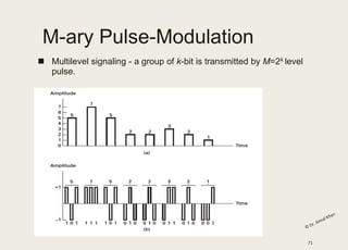
18. Binary Vs M-ary Modulation
■ Binary: Only two modulation levels
■ M-ary: Two or more than Two modulation
levels
88
25. 5.95
Frequency Shift Keying
■ The digital data stream changes the frequency of the carrier signal,
fc.
■ For example, a “1” could be represented by f1=fc +f, and a “0”
could be represented by f2=fc-f.
40. Average Energy per bit Vs
Average Energy per Symbol
■ Normally for a communication System Energy per bit is given
■ Difference between Bit duration and Symbol Duration
■ For Binary M-ary Schemes
110