Download as PDF, PPTX


![Sampling
참고 : http://www.engr.usask.ca/classes/EE/352/virtual_labs.htm
Sampling theory
Ideal sampling(=impulse sampling)
analog signal x(t ) has a bandwidth
x (t )
fm
(t nT )
n
Ts :sampling period
s
x s ( t ) x ( t ) x ( t )
x ( nT
n
1
X ( f ) F [ x ( t )]
Ts
s
) ( t nT s )
(f
n
fs
1
X s ( f ) X ( f )* X ( f )
Ts
디지털통신(Digital Comm.)
nf s )
1
: sampling frequency
Ts
n
X ( f nf s )
4](https://image.slidesharecdn.com/7-140121233502-phpapp02/85/7-4-320.jpg)


![펄스진폭 변조(PAM)
자연 표본화(Natural sampling)
PAM (t ) x(t ) pTs (t )
p (t ) rect (t )
P( ) sinc
2
~
pTs (t ) p(t ) Ts (t )
~
F [ pTs (t )] F [ p(t ) Ts (t )]
~
F [ p (t )]F [ Ts (t )]
~
s P ( ) s ( ).
ssinc
2
s
~
s ( )
k
sinc s
2
k
( k s )
c ( k ).
k
s
k
디지털통신(Digital Comm.)
11](https://image.slidesharecdn.com/7-140121233502-phpapp02/85/7-11-320.jpg)
![펄스진폭 변조(PAM)
F [ pTs (t )]
c ( k )
k
s
k
k
ck ssinc s .
2
x
*
PAM (t ) x(t ) pTs (t )
c ( k )
k
k
s
PAM ( )
F [ PAM (t )] F [ x(t ) pTs (t )]
1
F [ x(t )] F [ pTs (t )]
2
=
=
1
X ( )
ck ( k s )
2
k
ck
X ( k s ).
2
k
시간상의 표본화는 주파수상에서
의 주기화를 일으킨다
디지털통신(Digital Comm.)
12](https://image.slidesharecdn.com/7-140121233502-phpapp02/85/7-12-320.jpg)


![펄스진폭 변조(PAM)
평탄 표본화(flat-top sampling)
PAM (t ) T (t ) p(t )
x
s
~
Ts (t ) x(t )Ts (t )
x
x(kT ) (t kT )
n
s
s
PAM (t ) Ts (t ) p(t ) p(t ) x(kTs ) (t kTs )
x
k
x(kT )[ p(t ) (t kT )] x(kT ) p(t kT )
n
디지털통신(Digital Comm.)
s
s
n
s
s
19](https://image.slidesharecdn.com/7-140121233502-phpapp02/85/7-19-320.jpg)

![펄스진폭 변조(PAM)
■ 평탄 표본화(flat-top sampling)에서의 재구성(interpolation)
Equalizer : P(w)의
영향을 보상해주기
위해 사용
Flat-top sampling된 PAM signal를 복원하기 위해 LPF를 통과시키
면 신호의 왜곡 (signal distortion) 발생
[solution]
1. sampling pulse duration(τ) << sampling period( Ts )
2. LPF + equalizer (inverse transfer function of P(w))
equalizer : used to remove the distortion of band-limited pulse
디지털통신(Digital Comm.)
21](https://image.slidesharecdn.com/7-140121233502-phpapp02/85/7-21-320.jpg)


![PAM, PWM, PPM
t nTs
[ x(nTs ) C ]rect
PAM (t )
n
, C x(t ) max
t nTs
rect
PWM (t )
n
, kW x(nTs ) C
, kW x(t ) max C Ts kW x(t ) max .
t nTs a
rect
PPM (t )
n
, a k P x(nTs ) C
, k P x(t ) max C Ts k P x(t ) max .
디지털통신(Digital Comm.)
38](https://image.slidesharecdn.com/7-140121233502-phpapp02/85/7-38-320.jpg)
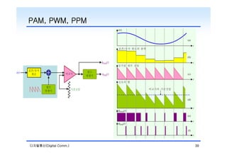

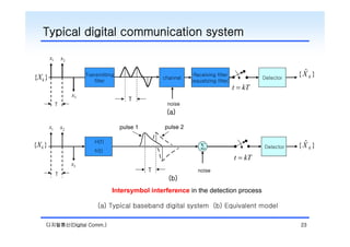
The document discusses pulse modulation techniques in digital communication. It introduces three main types of pulse modulation: PAM (Pulse Amplitude Modulation), PWM (Pulse Width Modulation), and PPM (Pulse Position Modulation). It then focuses on PAM modulation, discussing natural sampling and flat-top sampling. For natural sampling, it explains how the spectrum is periodic with harmonics determined by the sampling frequency. For flat-top sampling, it shows how the signal is reconstructed by filtering each sampled value. Proper filtering and equalization are needed to remove distortion from the band-limited sampling pulse.

![Multiband Transceivers - [Chapter 3] Basic Concept of Comm. Systems](https://cdn.slidesharecdn.com/ss_thumbnails/ch3-150613070933-lva1-app6892-thumbnail.jpg?width=640&height=640&fit=bounds)


![RF Module Design - [Chapter 1] From Basics to RF Transceivers](https://cdn.slidesharecdn.com/ss_thumbnails/rfch1-150613070344-lva1-app6892-thumbnail.jpg?width=640&height=640&fit=bounds)
![Multiband Transceivers - [Chapter 2] Noises and Linearities](https://cdn.slidesharecdn.com/ss_thumbnails/ch2-150613070933-lva1-app6892-thumbnail.jpg?width=640&height=640&fit=bounds)

![射頻電子 - [第六章] 低雜訊放大器設計](https://cdn.slidesharecdn.com/ss_thumbnails/ch6-150613065106-lva1-app6892-thumbnail.jpg?width=640&height=640&fit=bounds)
![Multiband Transceivers - [Chapter 4] Design Parameters of Wireless Radios](https://cdn.slidesharecdn.com/ss_thumbnails/ch4-150613070934-lva1-app6892-thumbnail.jpg?width=640&height=640&fit=bounds)