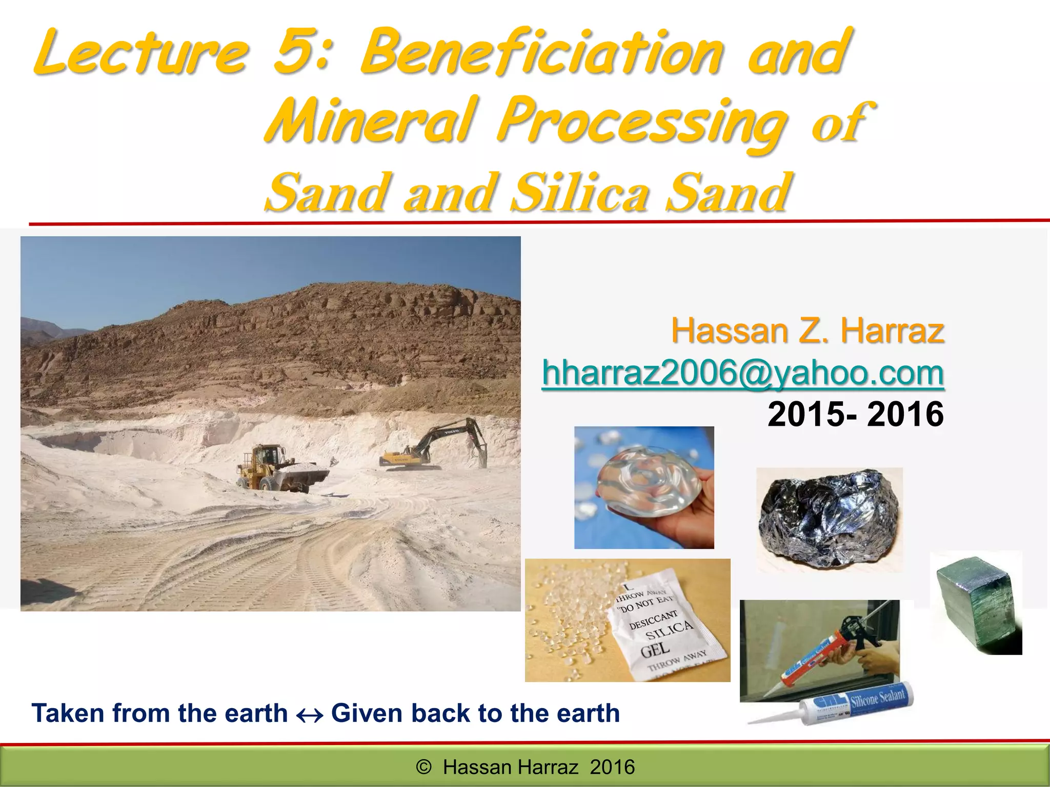
Hassan Z. Harraz
hharraz2006@yahoo.com
2015- 2016
© Hassan Harraz 2016
Taken from the earth  Given back to the earth
Lecture 5: Beneficiation and
Mineral Processing of
Sand and Silica Sand
OUTLİNE OF LECTURE 5:
Examples Mineral processing:
Sand and Silica Sand
Processing Sand
Sand into Silicon-Silicon carbide
Heavy Mineral Sand
 Separation of Heavy Minerals from Black Sand/Sand
 Zircon to Zirconium
 Ti-Bearing Minerals
© Hassan Harraz 2016
‫كوارتز‬ ‫منجم‬-‫هجليج‬ ‫ام‬ ‫منطقة‬-‫الحديدية‬ ‫للسبائك‬ ‫المصرية‬ ‫الشركة‬-‫علم‬ ‫مرسى‬ ‫ادفو‬ ‫طريق‬
© Hassan Harraz 2016
3
© Hassan Harraz 2016 4
© Hassan Harraz 2016
5
‫الناعمة‬ ‫الصفراء‬ ‫الرمال‬ ‫محاجر‬-‫البستان‬ ‫جبل‬-‫الدلنجات‬ ‫مركز‬-‫سمك‬ ‫يبلغ‬ ،‫البحيرة‬‫طبقة‬
‫من‬ ‫الرمال‬15‫الى‬20‫متر‬.
Outcrops of White Sandstones In New road of Zaafarana- Ain El-Sukhna, Gulf of Suez, Egypt
© Hassan Harraz 2016© Hassan Harraz 2016 6
Abu Darag White Sandstones Quarry In
Zaafarana - Ain El-Sukhna Area, Gulf of
Suez, Egypt
© Hassan Harraz 2016 7© Hassan Harraz 2016
© Hassan Harraz 2016
8
White Sand, Sinai-Egypt
© Hassan Harraz 2016
© Hassan Harraz 2016 9
Cross-bedding and scour in a fine sandstone, Sinai
© Hassan Harraz 2016
10
White Sand, Sinai
© Hassan Harraz 2016
© Hassan Harraz 2016 11
© Hassan Harraz 2016
12
6) SAND AND SILICA SAND
 Silicon (Si) is the 2nd most abundant element in earth’s
crust.
 Commonly found in its oxidized form (SiO2).
 Sand is a naturally occurring granular material
comprised of finely divided rock and mineral
particles.
 Sand is transported by wind and water and
deposited in the form of beaches, dunes, sand
spits, sand bars (placer deposits) etc.
 Sand constituents of sands are silica (SiO2), usually
in the form of quartz, and iron oxides.
Heavy Mineral Sands (or Black Sands)
• The most common constituents of sands are
silica (SiO2), usually in the form of quartz,
and iron oxides.
• Zircon, Ilmenite, and Rutile, Monazite, and
Garnet are co-product or by-product of heavy-
mineral sands.
 is an important source of zirconium, titanium,
thorium, tungsten, rare earth elements
© Hassan Harraz 2016 13
INDUSTRIAL SAND APPLICATIONS
Industry, Trade Applications and uses
Glass industry,
Fused silica industry
as glass sand for white container and flat glass, crystal glass, lead crystal, optical glass, special
glass, technical glass, borosilicate glass, glass wool and fused silica bricks and tools
Foundry industry foundry sand for molds and cores for metal castings
Construction materials and concrete
industry
as raw material for premixed dry mortar, polymer cement concrete, textured plaster, sandy
limestone, tiles, bricks, artificial cement stones, design and industrial floors etc.
Water purification as filter sands and gravels according to EN 12904 : 1999
Blasting abrasives and substitutes for mechanical surface treatment
Ceramic industry, Extenders for cement and resin bound masss, ceramic mass, filler, paints etc.
Iron processing and refractory industry
as raw material for filler sands (sliding gate fillers), fire-proof silica
bricks, silica ramming mixtures, repair systems etc.
Chemical industry as raw material for sodium silicate (water glass) and SiC
Electronics industry as fuse sands
Domestic animals hygiene, Aquaristic
equipment
as bird sand, parrot sand, chinchilla sand, terrarium sand and coloured quartz
Leisure and sports facilities
as special sand for playgrounds, riding-grounds, golf-courses, beach volleyball grounds, athletic
grounds, artificial lawn etc.
Sanding and Spreading
as braking sand for trains and trams, as winter sand for snow and ice control (straight or mixed
with salt)
© Hassan Harraz 2016 14
Sand
© Hassan Harraz 2016
15
Silica sand
© Hassan Harraz 2016 16
World resources of Silica Sand
• Silica sand resources is abundant
on the world.
• Its extraction is limited by
 geographic distribution
 quality requirements for
some uses
 environmental restrictions
• Extraction of theses resources is
dependent on whether it is
economic and are controlled by
the location of population
centers
http://minerals.er.usgs.gov/minerals/pubs/commodity/silica/780397.pdf
© Hassan Harraz 2016 17
Purposes for the Utilize of Silica Sand
Glass making,
Foundry casting, specialist building
applications, leisure ( e.g. golf course),
filters in numerous products,
Ceramics, Filtration, Plastics, the
manufacture of chemicals, metal &
Refractory, as additives in horticultural,
& agricultural products & simulating oil
production
© Hassan Harraz 2016
18
Specification of silica sand raw material
Chemistry
© Hassan Harraz 201619
Different Grade of Silica Sand
Different grade of Silica sand
Determination of indicators of grain size,
shape and grading distribution commonly
used for descriptions of silica sand
© Hassan Harraz 2016
20
6.1) Processing Silica Sand
What the analysed alternatives have in common is the mining and basic processing
operation.
The main assumptions for the first seven alternatives were as follows: surface mining using
bulldozers; transportation from a mining site to the processing plant by dumpers; then
washing and sizing in the processing plant which included sieve washing, attrition
scrubbing, hydro-cyclone classifying and dewatering.
The glass-grade silica sand production corresponded to alternatives, named as follows:
1) Basic processing by washing and sizing :
i) Basic/wet; and
ii) Basic/dry;
2) Electrostatic/dry separation;
3) Gravity concentration
i) Gravity /wet; and
ii) Gravity /dry;
4) Flotation concentration :
i) Flotation /wet; and
ii) Flotation /dry;
(note: Flotation was abandoned because of plant destruction Environment)
© Hassan Harraz 2016 21
Figure 1. Silica sand washing and sizing.
© Hassan Harraz 2016 22
(a) (b)
(c) (d)
(e) (f)
(g)
The glass sand requires 9 processing as follows:
(a) Stripping and extracting Silica
sand;
(b)Transportation system;
(c )Screening silica sand;
(d) Classified and Grading; sizing,
using hydrocyclones, attrition
scrubbing, ……etc
(e ) Washing Machines;
(f) Chemical/acid leaching to remove
Fe minerals and stained quartz
(g) Gravity (spirals, shaking tables,
Reichert cones), Spiralling and/or
tabling to remove heavy minerals.
(h) Magnetic (low/high intensity
dry/wet) and high tension
separation methods
(i) Dewatering.
6.2) Processing Sand
© Hassan Harraz 2016
Screening silica sand
Classified and grading
Silica sand washing Machines Spirals for removing heavy minerals
Magnetic Separation
Transportation system;Stripping and extracting Silica sand
23
Mineral sand slurry
moving down the
spiral gravity
separator with
increased
concentration of the
heavy minerals in the
center of the spiral.
© Hassan Harraz 2016
http://www.outokumpu.com
http://www.tiomin.com/
Zircon (ZrSiO4, SG.4.6 -4.7)
Quartz (SiO2, S.G. 2.6)
Rutile (TiO2, S.G. 4.2 – 4.5)
Ilmenite (FeTiO3, S.G. 4.7 – 4.8)
Monazite ({(Ce,La,Th)PO4}, S.G. 5.0 -5.3)
24
Silica Sand/
Quartz
Rutile
Zircon
Zircon (ZrSiO4, SG. 4.6 -4.7)
Quartz (SiO2, S.G. 2.6)
Rutile (TiO2, S.G. 4.2 – 4.5)
Ilmenite (FeTiO3, S.G. 4.7 – 4.8)
Monazite ({(Ce,La,Th)PO4}, S.G. 5.0 -5.3)
Gravity Separation
Electrostatic Separation
Electromagnetic Separation
Ilmenite
(Monazite)
© Hassan Harraz 2016
 One way to get
powder of desired
composition: from
minerals, simple
physical separation, +
chemical purification
to get products.
 Purity: often not very
high; used in
conventional ceramic
industry.
Raw Material
Black Sands / Heavy Mineral Sand
25
a) Screening sand;
b) Classified and Grading; sizing, using
hydrocyclones, attrition scrubbing,
……etc
c ) Washing Machines;
d) Chemical/acid leaching to remove Fe
minerals and stained quartz
© Hassan Harraz 2016 26
General Flow chart for
Beneficiation of Black Sand
© Hassan Harraz 2016
Water
Water
Water
Water
Water
Raw Black (Heavy) Sand
Heavy
Minerals
Water
Attrition
Screening, 300 m
Screening, 600 m Grit (>+600 m)
-600 m
Screening, 125 m
Magnetic Separation
Spiral Classifier
Dewatering + Hydrocyclones
Impurities
Iron Impurities
Scrubbing
Silica Sand
Silica Sand Product
(for Glass making/ Special Grade)
Glass Grade Sand
(Grade 1)
-600 +300 m-300 m
Zircon
Rutile
Ilmenite
Monazite
Ilmenite
(Monazite)
Electrostatic
Separation
Electromagnetic
Separation
Zircon
Rutile
27
© Hassan Harraz 2016 28
Typical grading curves for
processed glass sand moulding sand
© Hassan Harraz 2016
92%...0.125-0.5 mm
29
Grading envelope for
building sand and
silica sand
Grading curves of
filtration sands
© Hassan Harraz 2016 30
Recommended grading limits for
sports turf
sand (STRI)
sand used for golf
and bowling greens
(STRI)
© Hassan Harraz 2016 31
Every sand deposit has small amounts heavy minerals (minerals that are more
than 2.8 times as heavy as an equal volume of water). Many heavy minerals are
resistant to physical weathering and erosion, can therefore withstand sediment
reworking.
Some heavy minerals also have variable properties that can accurately indicate
their ultimate source.
In the lab, heavy minerals are separated from light minerals in heavy liquids and
mounted on glass slides for examination.
Heavy minerals
The ratio of light to heavy
minerals was determined
and the heavy ones
examined more closely.
300 heavy mineral grains
were counted.
Heavy minerals included
hornblende, biotite, zircon,
epidote and opaque
minerals such as one
would expect in potting
soil from weathered
granite.
Example of diversity of heavy
mineral grains in sand
What makes silicon unique and its chemistry the choice of a wide range
of environmentally friendly industrial applications ?
High natural abundance and easy availability of starting material (Sand)
(silicon is the second most abundant element on the earth)
An easy purification process to pure silicon.
A simple and cost efficient method for synthesis of organochlorosilanes
and their polymerization to silicone polymers.
Highly environmentally friendly end products with a diverse range of
proven applications.
Applications in steel refining & Semiconductor industry
Inorganic polymer industry based on Silicones
Industry based on piezo electricity of quartz
Industry based on silicates: from bricks, glass, cement to crockery
© Hassan Harraz 2016 34
6.3) SAND INTO SILICON-
SILICON CARBIDE (Si-SiC)
AND SILICONE
Unique Properties of Silicon
 Silicon mostly forms tetravalent compounds and to a minor extent divalent compounds
 Silicon forms non-toxic organo derivatives and therefore finds use in a wide range of
applications
 Si-O bond is one of the strongest bonds based on silicon and silicone polymers having Si-
O back bone are the most widely used inorganic polymers
 Silicon forms multiple bonds very rarely and to stabilize such bonds sterically bulky groups
are required
 Silicon is a semiconductor and finds use in solar cell fabrication and electronics
 Unlike carbon, silicon does not form stable double bonds with oxygen ( till 2014).
 Quartz (silicon dioxide) shows piezo electric properties.
 Silicon carbide has been the first LED and is still used
PROPERTY USE
Durability and low cost of the material Grinding, honing, water-jet cutting
High sublimation temperature of SiC Bearings and furnace parts.
High thermal conductivity, and high
maximum current density
Semiconductor material in electronics.
High voltage-dependent resistance Lightning arresters
Silicon: Properties and Uses
© Hassan Harraz 2016 35
6.3.1) Isolation and Purification of the Silicon
 The first step in making pure silicon is reduction of silica to an impure form of silicon known as
ferrosilicon.
 Ferrosilicon is an iron-silicon alloy that contains varying ratios of elemental silicon and iron.
SiO2 (Sand) + 2C (Coke) → Si(Fe) + CO2 (g)
(Ferrosilicon or Metallurgical-grade Si)
 Ferrosilicon accounts for ~ 80% of the world's production of elemental silicon. Silicon has a high
propensity to form bonds with oxygen and Ferrosilicon is primarily used by the steel industry to remove
dissolved oxygen in steel melt.
>2200oC
© Hassan Harraz 2016 36
Ultrapure silicon for solar cells and electronics
 For solar cell fabrication one requires silicon of much higher purity (+99.9%).
 For electronics grade the purity required is even higher (99.9999999% ; known as 9 nines).
 Although molten salt electrolysis of SiO2 or zone refining of metallurgy grade silicon can be carried out
for purification a more well known method and cost efficient is to convert the ferrosilicon to SiCl4 or
HSiCl3. These two relatively low boiling liquids can be purified to a very high level of purity by repeated
distillation:
Si(Fe) + Cl2 → SiCl4 (Liquid B.P.80oC) + FeCl3 (Solid)
 Trichlorosilane is produced by treating powdered ferrosilicon with blowing hydrogen chloride at 300°C
Si(Fe) + 3HCl (300oC) → HSiCl3 (Trichlorosilane: Liquid B.P. 31.8oC) + FeCl3 (Solid) + H2
 A convenient method to make ultrapure silicon has been the “Siemens Process” in which highly pure
silicon rods are exposed at high temperatures to trichlorosilane. Polycrystalline silicon gets deposited on
the silicon rod.
2HSiCl3 → Si + 3HCl + SiCl4
1150oC
High Purity Si -Rod
© Hassan Harraz 2016 37
SiO2 (Sand) + 2C (Coke)
{>2200oC} → Si(Fe) + CO2 (g)
Hydroclorination of MGS:
Si(Fe) + 3HCl (300oC) → HSiCl3 +
FeCl3 (Solid) + H2
2HSiCl3 (1150oC) → Si (High
Purity Si -Rod) + 3HCl + SiCl4
Distillation
Si(Fe) + Cl2 → SiCl4 (Liquid B.P.80oC) + FeCl3 (Solid)
Vaporization
and CVD of
HSiCl3
HCl and
H2 Recovery
1
2
3
4
5
Figure 1 : shows Flow Diagram for obtaining Isolation and Purification of the Silicon
6.3.2) Fumed Silica (Pyrogenic Silica) from SiCl4 : A
Useful Filler
Fumed silica serves as a universal thickening agent and an anticaking agent
(free-flow agent) in powders. Like silica gel, it serves as a desiccant.
It is used in cosmetics for its light-diffusing properties.
It is used as a light abrasive, in products like toothpaste.
Other uses include filler in silicone elastomer and viscosity adjustment in
paints, coatings, printing inks, adhesives and unsaturated polyester
resins.
Fumed silica is made mostly from flame pyrolysis of silicon tetrachloride
© Hassan Harraz 2016 38
Industrial Uses of Silicones
First human foot print on
moon made with silicone
soled shoes
Moon temperature
(-153 to +121°C)
© Hassan Harraz 2016 39
© Hassan Harraz 2016
40
SiC is also known as Carborundum.
SiC is known under trade names Carborundum, Crystalon, and Carbolon,
including black and green silicon carbide both with a shape of hex crystal.
The black silicon carbide is classified into coke-made and coal-made black
silicon carbide depending on different raw materials. The material is extremely
hard and sharp, with excellent chemical properties. The hardness is between
Diamond and Fused Alumina, but the mechanism hardness is higher than
Fused Alumina. The micro hardness is in the range of 2840-3320kg/mm². Its
hardness is 13 Mohos
, scale.
Crystal Structure of
Silicon Carbide
Structure and properties
Polymorphs of silicon carbide
SiC exists in ~250 crystalline forms.
The polymorphism of SiC include various amorphous phases observed in thin films and fibers, as
well as a large family of similar crystalline structures called Polytypes.
They are variations of the same chemical compound that are identical in two dimensions and
differ in the third. Thus, they can be viewed as layers stacked in a certain sequence.
α-SiC is the most commonly encountered polymorph; it is formed at temperatures greater
than 1700oC and has a hexagonal crystal structure (similar to Wurtzite).
β-SiC, with a zinc blende crystal structure (similar to diamond), is formed at temperatures
below 1700oC. Until recently, the beta form has had relatively few commercial uses, although
there is now increasing interest in its use as a support for heterogeneous catalysts, owing to
its higher surface area compared to the alpha form.
Pure SiC is colorless. The brown to black color of industrial product results from iron
impurities. The rainbow-like luster of the crystals is caused by a passivation layer of silicon
dioxide that forms on the surface.
The high sublimation temperature of SiC (approximately 2700oC) makes it useful for bearings
and furnace parts. SiC does not melt at any known pressure. It is also highly inert chemically.
There is currently much interest in its use as a semiconductor material in electronics, where
its high thermal conductivity, high electric field breakdown strength and high maximum
current density make it more promising than silicon for high-powered devices. SiC also has a
very low coefficient of thermal expansion and experiences no phase transitions that would
cause discontinuities in thermal expansion.
© Hassan Harraz 201642
For example the α-SiC can also be called 2H-, 4H- or 6H-SiC, depending on the
unit cell, while β-SiC can also be called 3C-SiC because of the ABC stacking ...
3C-SiC
6H-SiC
2H-SiC
4H-SiC
β-SiC
α-SiC
α-SiC
α-SiC
Si atom
C atom
© Hassan Harraz 2016 43
© Hassan Harraz 201644
Crystal Structure of
Silicon Carbide
SiC has:
high hardness
high thermal consistency
very good resistance at high temperatures
low thermal expansion
electrical conductivity
is a semiconductor
non linear electrical resistance
Substantial space heritage exists:
Space science applications
Military applications
Structures and reflecting optics
Si and C as alloying additive - Silicon Carbide dissociates in molten iron and the
silicon reacts with the metal oxides in the melt. This reaction is of use in the
metallurgy of iron and steel.
SiC Properties
SiC is sharp but fragile with good heat-resistance, heat-conductibility, can be antacid and
antalkali, and lower dilatability.
Moissanite ring natural light
© Hassan Harraz 2016 45
© Hassan Harraz 2016 46
 Silicon and Carbon are released from SiC as charged
atoms.
 Carbon works as a de-oxidiser removing free oxygen
and reducing unstable oxides (e.g. FeO and MnO),
typically:
SiC + FeO → Si + Fe + CO(g)
 Removing these elements to the slag and increasing
the life of furnace linings
Benefits of SiC as a de-oxidizing agent
© Hassan Harraz 2016 47
SiC Production Process
a) Raw Materials Preparation
Furnace mixes are calculated to obtain a specified SiO2
/C ratio, usually ~1.70.
A furnace mix prepared to strict stoichiometry for the
overall reaction will state tha150 t of SiO2 are to be
mixed with 90t of carbon (e.g. 50% silica, 40% coke,
7% sawdust, and 3% salt) to produce 100 t of SiC
and 140t t of CO.
© Hassan Harraz 2016
48
b) Manufacturing Processes for SiC
 Silicon carbide is manufactured industrially by the electrochemical reaction of
high purity silica or quartz sand with carbon in an electric resistance furnace
(Acheson process):
SiO2 + 3C → SiC + 2CO(gas)
The process is an endothermic reaction requiring between 8,000 – 10,000kWh
per tonne of product.
Acheson process to produce α-SiC by reacting of ~50% high-purity silica
sand or quartz, 40% finely ground low-sulfur coke, 7% sawdust, and 3%
salt (Sodium Chloride: NaCl) in a resistance electric arc furnace for 36 hours at
2200-2400oC .
Preferred carbons are petroleum coke (pitch coke) and anthracite.
 Addition of (3%) Sodium Chloride (NaCl) ensures the removal of trouble some
impurities as volatile chlorides. The presence of Sawdust (7%) increases the
porosity of the reaction mixture and eases outgassing. The process gives off
carbon monoxide (CO).
There are four chemical reactions in the process that produces silicon carbide
(SiC) at 2000-3000oC:
C + SiO2 → SiO(g) + CO(g)
SiO2 + CO (g) → SiO + CO2 (g)
C + CO2 (g) → 2CO(g)
2C + SiO → α-SiC + CO(g)
The first light emitting diodes were produced using silicon carbide from the
Acheson process.
>2200oC
© Hassan Harraz 2016 49
© Hassan Harraz 201650
SiC Furnace Recovery
© Hassan Harraz 2016
51
 The electric furnaces, in which this reaction is carried out, are
~1533 m3 in size and are lined with refractory material.
Electrodes at opposite ends are connected to a graphite core.
The furnace is filled round this core with the reaction mixture
and electrically heated to 2200 to 2400°C. The heating up time
is ~18 h and the reaction time a further ~18 h. After cooling,
the sides of the furnaces are removed and the unreacted
material on the edges removed.
 The material formed in the Acheson furnace varies in purity,
according to its distance from the graphite resistor heat
source. Colorless, pale yellow and green crystals have the
highest purity and are found closest to the resistor. The color
changes to blue and black at greater distance from the
resistor, and these darker crystals are less pure.
 The SiC, which has formed round the graphite core, is broken
up and separated into different qualities:
 The purest SiC is bright green (99.8% SiC), the color
changing with decreasing SiC-content from dark green
(99.5% SiC) to black (99% SiC) to gray (90% SiC).
© Hassan Harraz 2016 52
Inside a SiC Furnace
30-40% SiC
85% SiC
97%+
SiC
Pure Silicon Carbide
Less Pure Silicon Carbide
Cross-sectional view of a
typical cylinder, showing
the interior cavity in which
graphite is formed, the pure
silicon carbide body and
the less pure material in the
reactant zone.
© Hassan Harraz 2016 53
70 t of raw mixture yields 8 to 14 t of high grade SiC and 6 to 12 kWh of
energy are required to produce 1 kg of raw SiC.
The raw SiC is processed by crushing in jaw crushers or hammer mills and
subsequent fine grinding in ball mills.
Very pure SiC qualities are obtained by chemical treatment with sulfuric acid,
sodium hydroxide or hydrofluoric acid.
SiC is remarkable for its unusually large variety of different morphologies,
which differ in their stacking sequences of hexagonal and rhombohedral
layers. All hexagonal and rhombohedral forms are often simply described
as α-SiC. The commercially available SiC produced by the Acheson process
is α-SiC.
The manufacture of cubic β-SiC, which is favored at temperatures below
2000°C, or mixtures of α- and β-SiC is carried out by deposition from the
gas phase (Chemical Vapor Deposition (CVD)).
 β-SiC powder with good sintering properties and small crystallite size is {e.g.
obtained by the thermal decomposition of alkyl silanes or alkyl dichlorosilanes in
plasmas or flow reactors at temperatures above 1000°C:
CH3SiCl3 (>1000oC) → β-SiC +3HCl
In the manufacture of synthetic graphite, the Acheson process is run for
approximately 20 hours, with currents of 200 A, and voltages of 40,000–50,000
V (8–10 MW). The purity of graphite achievable using the process is 99.5%.
© Hassan Harraz 2016 54
Lely process
 To make Pure SiC crystal, in which SiC powder is sublimated into high-
temperature species of silicon, carbon, silicon dicarbide (SiC2), and disilicon
carbide (Si2C) in an argon gas ambient at 2500oC and redeposited into
flake-like single crystals, sized up to 2×2 cm, at a slightly colder substrate.
This process yields high-quality single crystals, mostly of 6H-SiC phase
(because of high growth temperature).
3SiC (Argon (g), 2500oC) → Si2C + SiC2
A modified Lely process involving induction heating in graphite crucibles
yields even larger single crystals of 10 cm in diameter.
 Cubic β-SiC is usually grown by the more expensive process of
chemical vapor deposition (CVD). Homoepitaxial and Heteroepitaxial
SiC layers can be grown employing both gas and liquid phase
approaches.
© Hassan Harraz 2016 55
6.4.1) Zircon Containing Raw Materials
 The principal economic source of zirconium (Zr) is the zirconium silicate mineral, zircon
(ZrSiO4).
 Zircon is also the primary source of all hafnium (Hf).
 Zirconium and hafnium are contained in zircon at a ratio of about 50 to 1.
 Zircon is a coproduct or byproduct of the mining and processing of heavy-mineral sands
Hawks Nest, a beach sand deposit within Murray Bay (Australia)
operated by Mineral Deposits Ltd. They extract 21,147 t of
concentrate from about 20’000’000 t of sand. This deposit has a
very low grade (0.2 -0.3wt% heavy minerals), but large reserves.
The sand is extracted by a dredge.
Murray Bay heavy mineral
concentrate dominated by zircon
(colorless, rounded grains) and
rutile (deep yellow grains)
(Image length 20mm)
http://www.mineraldeposits.com.au/
6.4) ZIRCON TO ZIRCONIUM
© Hassan Harraz 2016 56
i) Chemical extraction of zirconia (ZrO2) from zircon (ZrSiO4) ore
6.4.2) Zirconium Extraction
• The starting raw materials for the production of zirconia are the minerals Zircon (ZrSiO4)
and, to a lesser extent, Baddeleyite (β- ZrO2).
• To extract zirconium (Zr), we first Chemically extraction of zirconia (ZrO2) from
zircon (ZrSiO4) ore.
 There are two methods to make zirconia: thermal decomposition and
precipitation:
 Thermal Decomposition Method: high temperature melting and
decomposition (use arc furnace or plasma arc) >1750oC;  quench  use
acid to dissolve ZrO2 or alkaline for SiO2
 Precipitation Method:
 Zirconia (ZrO2) of 99% purity is obtained by the caustic fusion of zircon
(ZrSiO4).
 zircon + NaOH  high temperature reaction  Na2ZrO3 + Na2SiO3  +
water  filtration to remove Na2SiO3.nH2O  crude sodium zirconate 
+ HCl  filtration to remove SiO2 colloids  get ZrOCl2 – HCl solution 
evaporative concentration  crystallization  filtration to remove
impurities (Fe, Ti, Na, Al, HCl …etc)  get ZrOCl2.8H2O  repeat and
secondary crystallization  high purity ZrOCl2.8H2O  calcination 
zirconia (ZrO2)…{can be represented by the flow diagram: Fig 1}.
© Hassan Harraz 2016 57
Figure 1 : shows Flow Diagram for obtaining zirconia from zircon
Zircon sand (zirconium silicate ZrSiO4)
fusion with sodium hydroxide (NaOH) at 870 K
Zirconium hydroxide, Zr(OH)4, formed by hydrolysis.
Sodium silicate removed
Zirconyl chloride, ZrOCl2
dissolution in hydrochloric acid (HCl)
washing with water
precipitation of pure intermediates and reactions
with amonia (NH4OH) or sodium hydroxide (NaOH) or sodium carbonate(Na2CO3)
Zirconia Powder
(ZrO2)
Solutions of
zirconium compounds
ZrOCl2.+ 4NaOH = Na2O +2NaCl + Zr(OH)4
ZrOCl2 + 2Na2CO3 = Na2O +2NaCl + Zr(CO3)2
Zirconium hydroxide,
Zr(OH)4
Zirconium carbonate,
Zr(CO3)2
Calcination
Sodium silicate (Na2SiO3) and sodium zirconate (Na2ZrO3)
Zr(OH)4 + 2HCl → ZrOCl2 + 3H2O
Na2ZrO3 + 3H2O→ Zr(OH)4 + 2NaOH
ZrSiO4 + 4NaOH (Fusion) → Na2ZrO3 + Na2SiO3 + 2H2O
Calcination
Zirconia Powder
(ZrO2)
© Hassan Harraz 2016 58
 The Kroll method is used for zirconium and involves the action of
chlorine and carbon .
 The resultant zirconium tetrachloride (ZrCl4) is separated from the iron
trichloride (FeCl3), by fractional distillation.
 Finally, zirconium tetrachloride (ZrCl4) is reduced to metallic zirconium
by reduction with magnesium (Mg).
 Air is excluded so as to prevent contamination of the product with
oxygen or nitrogen.
ZrO2 + 2Cl2 + 2C (900°C)  ZrCl4 + 2CO
ZrCl4 + 2Mg (1100°C)  2MgCl2 + Zr
 Excess magnesium and magnesium dichloride is removed from the product by
treatment with water and hydrochloric acid to leave a zirconium "sponge".
 This can be melted under helium by electrical heating.
ii) Chemical extraction of zirconium (Zr) from zirconia (ZrO2)
© Hassan Harraz 2016 59
Titania (TiO2) is produced from Ti-bearing ore (i.e., ilmenite FeTiO3) by the
sulfate or chloride process:
i) Sulfate process:
In the sulfate process Ti-bearing ore (i.e., ilmenite FeTiO3) is treat with
sulfuric acid at 150-180°C to from the soluble titanyl sulfate TiOSO4
FeTiO3+ 2H2SO4+ 5H2O→ FeSO4.7H2O +TiOSO4
After removing undissolved solids and then the iron sulfate precipitate the
titanyl sulfate is hydrolyzed at 90°C to precipitate the hydroxide TiO(OH)2
TiOSO4 + 2H2O → TiO(OH)2 + H2
The titanyl hydroxide is calcined at about 1000oC to produce titania (TiO2).
ii) Chloride process:
 In the chloride process, a high-grade titania (Ti-bearing) ore is chlorinate in
the presence of Coke (carbon) at 900-1000°C and the chloride TiCl4 formed
is subsequently oxidized to TiO2, as following:
2FeTiO3 + 3C + 6Cl2 → 2TiCl4 + 2FeCl2 + 3CO2
TiCl4 + 2O → TiO2 + 2Cl2↑
6.5) Ti-BEARING MINERALS
© Hassan Harraz 2016 60
© Hassan Harraz 2016
61
Figure 1 : Flow Chart of Titanium Oxide Process
Chlorination:
React Ti-bearing ore with chlorine (Cl2) and
coke (carbon) at 900-1000°C to form TiCl4
and metal chloride:
2FeTiO3 + 3C + 6Cl2 → 2TiCl4 + 2FeCl2 + 3CO2↑
 Separate TiCl4 from metal chlorides and
purify TiCl4.
Oxidation
 Convert TiCl4 to TiO2 particles by reacting
with oxygen:.
TiCl4 + 2O → TiO2 + 2Cl2↑
 Recycle chlorine back to chlorination
Finishing
 Coat TiO2 particles with additives to provide
desired properties based on market
application.
 Mill TiO2 to desirable particle size using
steam.
© Hassan Harraz 2016 62
Figure 2 : Flow Chart of Titanium metal Process
Chlorination
Heat
Waste
Treatment
Vapour
Chlorine
(Cl2)
Ti
Ti-bearing ore
Chlorine (Cl2)
Coke ( C)
Ti + NaCl
Filter
Wash
Filter
Water
TiCl4
Ti
NaCl
Ti
NaCl
Ti
NaCl (aq)
NaCl (aq)
NaCl (s)
Liquid
Sodium
Na
Na
electrolysis Dry
© Hassan Harraz 2016 63
Follow me on Social Media
http://facebook.com/hzharraz
http://www.slideshare.net/hzharraz
https://www.linkedin.com/in/hassan-harraz-3172b235
© Hassan Harraz 2016

Beneficiation and mineral processing of sand and silica sand

  • 1.
    Hassan Z. Harraz hharraz2006@yahoo.com 2015-2016 © Hassan Harraz 2016 Taken from the earth  Given back to the earth Lecture 5: Beneficiation and Mineral Processing of Sand and Silica Sand
  • 2.
    OUTLİNE OF LECTURE5: Examples Mineral processing: Sand and Silica Sand Processing Sand Sand into Silicon-Silicon carbide Heavy Mineral Sand  Separation of Heavy Minerals from Black Sand/Sand  Zircon to Zirconium  Ti-Bearing Minerals © Hassan Harraz 2016
  • 3.
    ‫كوارتز‬ ‫منجم‬-‫هجليج‬ ‫ام‬‫منطقة‬-‫الحديدية‬ ‫للسبائك‬ ‫المصرية‬ ‫الشركة‬-‫علم‬ ‫مرسى‬ ‫ادفو‬ ‫طريق‬ © Hassan Harraz 2016 3
  • 4.
  • 5.
    © Hassan Harraz2016 5 ‫الناعمة‬ ‫الصفراء‬ ‫الرمال‬ ‫محاجر‬-‫البستان‬ ‫جبل‬-‫الدلنجات‬ ‫مركز‬-‫سمك‬ ‫يبلغ‬ ،‫البحيرة‬‫طبقة‬ ‫من‬ ‫الرمال‬15‫الى‬20‫متر‬.
  • 6.
    Outcrops of WhiteSandstones In New road of Zaafarana- Ain El-Sukhna, Gulf of Suez, Egypt © Hassan Harraz 2016© Hassan Harraz 2016 6
  • 7.
    Abu Darag WhiteSandstones Quarry In Zaafarana - Ain El-Sukhna Area, Gulf of Suez, Egypt © Hassan Harraz 2016 7© Hassan Harraz 2016
  • 8.
    © Hassan Harraz2016 8 White Sand, Sinai-Egypt © Hassan Harraz 2016
  • 9.
    © Hassan Harraz2016 9 Cross-bedding and scour in a fine sandstone, Sinai © Hassan Harraz 2016
  • 10.
    © Hassan Harraz2016 10 White Sand, Sinai © Hassan Harraz 2016
  • 11.
  • 12.
  • 13.
    6) SAND ANDSILICA SAND  Silicon (Si) is the 2nd most abundant element in earth’s crust.  Commonly found in its oxidized form (SiO2).  Sand is a naturally occurring granular material comprised of finely divided rock and mineral particles.  Sand is transported by wind and water and deposited in the form of beaches, dunes, sand spits, sand bars (placer deposits) etc.  Sand constituents of sands are silica (SiO2), usually in the form of quartz, and iron oxides. Heavy Mineral Sands (or Black Sands) • The most common constituents of sands are silica (SiO2), usually in the form of quartz, and iron oxides. • Zircon, Ilmenite, and Rutile, Monazite, and Garnet are co-product or by-product of heavy- mineral sands.  is an important source of zirconium, titanium, thorium, tungsten, rare earth elements © Hassan Harraz 2016 13
  • 14.
    INDUSTRIAL SAND APPLICATIONS Industry,Trade Applications and uses Glass industry, Fused silica industry as glass sand for white container and flat glass, crystal glass, lead crystal, optical glass, special glass, technical glass, borosilicate glass, glass wool and fused silica bricks and tools Foundry industry foundry sand for molds and cores for metal castings Construction materials and concrete industry as raw material for premixed dry mortar, polymer cement concrete, textured plaster, sandy limestone, tiles, bricks, artificial cement stones, design and industrial floors etc. Water purification as filter sands and gravels according to EN 12904 : 1999 Blasting abrasives and substitutes for mechanical surface treatment Ceramic industry, Extenders for cement and resin bound masss, ceramic mass, filler, paints etc. Iron processing and refractory industry as raw material for filler sands (sliding gate fillers), fire-proof silica bricks, silica ramming mixtures, repair systems etc. Chemical industry as raw material for sodium silicate (water glass) and SiC Electronics industry as fuse sands Domestic animals hygiene, Aquaristic equipment as bird sand, parrot sand, chinchilla sand, terrarium sand and coloured quartz Leisure and sports facilities as special sand for playgrounds, riding-grounds, golf-courses, beach volleyball grounds, athletic grounds, artificial lawn etc. Sanding and Spreading as braking sand for trains and trams, as winter sand for snow and ice control (straight or mixed with salt) © Hassan Harraz 2016 14
  • 15.
  • 16.
    Silica sand © HassanHarraz 2016 16
  • 17.
    World resources ofSilica Sand • Silica sand resources is abundant on the world. • Its extraction is limited by  geographic distribution  quality requirements for some uses  environmental restrictions • Extraction of theses resources is dependent on whether it is economic and are controlled by the location of population centers http://minerals.er.usgs.gov/minerals/pubs/commodity/silica/780397.pdf © Hassan Harraz 2016 17
  • 18.
    Purposes for theUtilize of Silica Sand Glass making, Foundry casting, specialist building applications, leisure ( e.g. golf course), filters in numerous products, Ceramics, Filtration, Plastics, the manufacture of chemicals, metal & Refractory, as additives in horticultural, & agricultural products & simulating oil production © Hassan Harraz 2016 18
  • 19.
    Specification of silicasand raw material Chemistry © Hassan Harraz 201619
  • 20.
    Different Grade ofSilica Sand Different grade of Silica sand Determination of indicators of grain size, shape and grading distribution commonly used for descriptions of silica sand © Hassan Harraz 2016 20
  • 21.
    6.1) Processing SilicaSand What the analysed alternatives have in common is the mining and basic processing operation. The main assumptions for the first seven alternatives were as follows: surface mining using bulldozers; transportation from a mining site to the processing plant by dumpers; then washing and sizing in the processing plant which included sieve washing, attrition scrubbing, hydro-cyclone classifying and dewatering. The glass-grade silica sand production corresponded to alternatives, named as follows: 1) Basic processing by washing and sizing : i) Basic/wet; and ii) Basic/dry; 2) Electrostatic/dry separation; 3) Gravity concentration i) Gravity /wet; and ii) Gravity /dry; 4) Flotation concentration : i) Flotation /wet; and ii) Flotation /dry; (note: Flotation was abandoned because of plant destruction Environment) © Hassan Harraz 2016 21
  • 22.
    Figure 1. Silicasand washing and sizing. © Hassan Harraz 2016 22
  • 23.
    (a) (b) (c) (d) (e)(f) (g) The glass sand requires 9 processing as follows: (a) Stripping and extracting Silica sand; (b)Transportation system; (c )Screening silica sand; (d) Classified and Grading; sizing, using hydrocyclones, attrition scrubbing, ……etc (e ) Washing Machines; (f) Chemical/acid leaching to remove Fe minerals and stained quartz (g) Gravity (spirals, shaking tables, Reichert cones), Spiralling and/or tabling to remove heavy minerals. (h) Magnetic (low/high intensity dry/wet) and high tension separation methods (i) Dewatering. 6.2) Processing Sand © Hassan Harraz 2016 Screening silica sand Classified and grading Silica sand washing Machines Spirals for removing heavy minerals Magnetic Separation Transportation system;Stripping and extracting Silica sand 23
  • 24.
    Mineral sand slurry movingdown the spiral gravity separator with increased concentration of the heavy minerals in the center of the spiral. © Hassan Harraz 2016 http://www.outokumpu.com http://www.tiomin.com/ Zircon (ZrSiO4, SG.4.6 -4.7) Quartz (SiO2, S.G. 2.6) Rutile (TiO2, S.G. 4.2 – 4.5) Ilmenite (FeTiO3, S.G. 4.7 – 4.8) Monazite ({(Ce,La,Th)PO4}, S.G. 5.0 -5.3) 24
  • 25.
    Silica Sand/ Quartz Rutile Zircon Zircon (ZrSiO4,SG. 4.6 -4.7) Quartz (SiO2, S.G. 2.6) Rutile (TiO2, S.G. 4.2 – 4.5) Ilmenite (FeTiO3, S.G. 4.7 – 4.8) Monazite ({(Ce,La,Th)PO4}, S.G. 5.0 -5.3) Gravity Separation Electrostatic Separation Electromagnetic Separation Ilmenite (Monazite) © Hassan Harraz 2016  One way to get powder of desired composition: from minerals, simple physical separation, + chemical purification to get products.  Purity: often not very high; used in conventional ceramic industry. Raw Material Black Sands / Heavy Mineral Sand 25 a) Screening sand; b) Classified and Grading; sizing, using hydrocyclones, attrition scrubbing, ……etc c ) Washing Machines; d) Chemical/acid leaching to remove Fe minerals and stained quartz
  • 26.
  • 27.
    General Flow chartfor Beneficiation of Black Sand © Hassan Harraz 2016 Water Water Water Water Water Raw Black (Heavy) Sand Heavy Minerals Water Attrition Screening, 300 m Screening, 600 m Grit (>+600 m) -600 m Screening, 125 m Magnetic Separation Spiral Classifier Dewatering + Hydrocyclones Impurities Iron Impurities Scrubbing Silica Sand Silica Sand Product (for Glass making/ Special Grade) Glass Grade Sand (Grade 1) -600 +300 m-300 m Zircon Rutile Ilmenite Monazite Ilmenite (Monazite) Electrostatic Separation Electromagnetic Separation Zircon Rutile 27
  • 28.
  • 29.
    Typical grading curvesfor processed glass sand moulding sand © Hassan Harraz 2016 92%...0.125-0.5 mm 29
  • 30.
    Grading envelope for buildingsand and silica sand Grading curves of filtration sands © Hassan Harraz 2016 30
  • 31.
    Recommended grading limitsfor sports turf sand (STRI) sand used for golf and bowling greens (STRI) © Hassan Harraz 2016 31
  • 32.
    Every sand deposithas small amounts heavy minerals (minerals that are more than 2.8 times as heavy as an equal volume of water). Many heavy minerals are resistant to physical weathering and erosion, can therefore withstand sediment reworking. Some heavy minerals also have variable properties that can accurately indicate their ultimate source. In the lab, heavy minerals are separated from light minerals in heavy liquids and mounted on glass slides for examination. Heavy minerals
  • 33.
    The ratio oflight to heavy minerals was determined and the heavy ones examined more closely. 300 heavy mineral grains were counted. Heavy minerals included hornblende, biotite, zircon, epidote and opaque minerals such as one would expect in potting soil from weathered granite. Example of diversity of heavy mineral grains in sand
  • 34.
    What makes siliconunique and its chemistry the choice of a wide range of environmentally friendly industrial applications ? High natural abundance and easy availability of starting material (Sand) (silicon is the second most abundant element on the earth) An easy purification process to pure silicon. A simple and cost efficient method for synthesis of organochlorosilanes and their polymerization to silicone polymers. Highly environmentally friendly end products with a diverse range of proven applications. Applications in steel refining & Semiconductor industry Inorganic polymer industry based on Silicones Industry based on piezo electricity of quartz Industry based on silicates: from bricks, glass, cement to crockery © Hassan Harraz 2016 34 6.3) SAND INTO SILICON- SILICON CARBIDE (Si-SiC) AND SILICONE
  • 35.
    Unique Properties ofSilicon  Silicon mostly forms tetravalent compounds and to a minor extent divalent compounds  Silicon forms non-toxic organo derivatives and therefore finds use in a wide range of applications  Si-O bond is one of the strongest bonds based on silicon and silicone polymers having Si- O back bone are the most widely used inorganic polymers  Silicon forms multiple bonds very rarely and to stabilize such bonds sterically bulky groups are required  Silicon is a semiconductor and finds use in solar cell fabrication and electronics  Unlike carbon, silicon does not form stable double bonds with oxygen ( till 2014).  Quartz (silicon dioxide) shows piezo electric properties.  Silicon carbide has been the first LED and is still used PROPERTY USE Durability and low cost of the material Grinding, honing, water-jet cutting High sublimation temperature of SiC Bearings and furnace parts. High thermal conductivity, and high maximum current density Semiconductor material in electronics. High voltage-dependent resistance Lightning arresters Silicon: Properties and Uses © Hassan Harraz 2016 35
  • 36.
    6.3.1) Isolation andPurification of the Silicon  The first step in making pure silicon is reduction of silica to an impure form of silicon known as ferrosilicon.  Ferrosilicon is an iron-silicon alloy that contains varying ratios of elemental silicon and iron. SiO2 (Sand) + 2C (Coke) → Si(Fe) + CO2 (g) (Ferrosilicon or Metallurgical-grade Si)  Ferrosilicon accounts for ~ 80% of the world's production of elemental silicon. Silicon has a high propensity to form bonds with oxygen and Ferrosilicon is primarily used by the steel industry to remove dissolved oxygen in steel melt. >2200oC © Hassan Harraz 2016 36 Ultrapure silicon for solar cells and electronics  For solar cell fabrication one requires silicon of much higher purity (+99.9%).  For electronics grade the purity required is even higher (99.9999999% ; known as 9 nines).  Although molten salt electrolysis of SiO2 or zone refining of metallurgy grade silicon can be carried out for purification a more well known method and cost efficient is to convert the ferrosilicon to SiCl4 or HSiCl3. These two relatively low boiling liquids can be purified to a very high level of purity by repeated distillation: Si(Fe) + Cl2 → SiCl4 (Liquid B.P.80oC) + FeCl3 (Solid)  Trichlorosilane is produced by treating powdered ferrosilicon with blowing hydrogen chloride at 300°C Si(Fe) + 3HCl (300oC) → HSiCl3 (Trichlorosilane: Liquid B.P. 31.8oC) + FeCl3 (Solid) + H2  A convenient method to make ultrapure silicon has been the “Siemens Process” in which highly pure silicon rods are exposed at high temperatures to trichlorosilane. Polycrystalline silicon gets deposited on the silicon rod. 2HSiCl3 → Si + 3HCl + SiCl4 1150oC High Purity Si -Rod
  • 37.
    © Hassan Harraz2016 37 SiO2 (Sand) + 2C (Coke) {>2200oC} → Si(Fe) + CO2 (g) Hydroclorination of MGS: Si(Fe) + 3HCl (300oC) → HSiCl3 + FeCl3 (Solid) + H2 2HSiCl3 (1150oC) → Si (High Purity Si -Rod) + 3HCl + SiCl4 Distillation Si(Fe) + Cl2 → SiCl4 (Liquid B.P.80oC) + FeCl3 (Solid) Vaporization and CVD of HSiCl3 HCl and H2 Recovery 1 2 3 4 5 Figure 1 : shows Flow Diagram for obtaining Isolation and Purification of the Silicon
  • 38.
    6.3.2) Fumed Silica(Pyrogenic Silica) from SiCl4 : A Useful Filler Fumed silica serves as a universal thickening agent and an anticaking agent (free-flow agent) in powders. Like silica gel, it serves as a desiccant. It is used in cosmetics for its light-diffusing properties. It is used as a light abrasive, in products like toothpaste. Other uses include filler in silicone elastomer and viscosity adjustment in paints, coatings, printing inks, adhesives and unsaturated polyester resins. Fumed silica is made mostly from flame pyrolysis of silicon tetrachloride © Hassan Harraz 2016 38
  • 39.
    Industrial Uses ofSilicones First human foot print on moon made with silicone soled shoes Moon temperature (-153 to +121°C) © Hassan Harraz 2016 39
  • 40.
  • 41.
    SiC is alsoknown as Carborundum. SiC is known under trade names Carborundum, Crystalon, and Carbolon, including black and green silicon carbide both with a shape of hex crystal. The black silicon carbide is classified into coke-made and coal-made black silicon carbide depending on different raw materials. The material is extremely hard and sharp, with excellent chemical properties. The hardness is between Diamond and Fused Alumina, but the mechanism hardness is higher than Fused Alumina. The micro hardness is in the range of 2840-3320kg/mm². Its hardness is 13 Mohos , scale. Crystal Structure of Silicon Carbide
  • 42.
    Structure and properties Polymorphsof silicon carbide SiC exists in ~250 crystalline forms. The polymorphism of SiC include various amorphous phases observed in thin films and fibers, as well as a large family of similar crystalline structures called Polytypes. They are variations of the same chemical compound that are identical in two dimensions and differ in the third. Thus, they can be viewed as layers stacked in a certain sequence. α-SiC is the most commonly encountered polymorph; it is formed at temperatures greater than 1700oC and has a hexagonal crystal structure (similar to Wurtzite). β-SiC, with a zinc blende crystal structure (similar to diamond), is formed at temperatures below 1700oC. Until recently, the beta form has had relatively few commercial uses, although there is now increasing interest in its use as a support for heterogeneous catalysts, owing to its higher surface area compared to the alpha form. Pure SiC is colorless. The brown to black color of industrial product results from iron impurities. The rainbow-like luster of the crystals is caused by a passivation layer of silicon dioxide that forms on the surface. The high sublimation temperature of SiC (approximately 2700oC) makes it useful for bearings and furnace parts. SiC does not melt at any known pressure. It is also highly inert chemically. There is currently much interest in its use as a semiconductor material in electronics, where its high thermal conductivity, high electric field breakdown strength and high maximum current density make it more promising than silicon for high-powered devices. SiC also has a very low coefficient of thermal expansion and experiences no phase transitions that would cause discontinuities in thermal expansion. © Hassan Harraz 201642
  • 43.
    For example theα-SiC can also be called 2H-, 4H- or 6H-SiC, depending on the unit cell, while β-SiC can also be called 3C-SiC because of the ABC stacking ... 3C-SiC 6H-SiC 2H-SiC 4H-SiC β-SiC α-SiC α-SiC α-SiC Si atom C atom © Hassan Harraz 2016 43
  • 44.
    © Hassan Harraz201644 Crystal Structure of Silicon Carbide
  • 45.
    SiC has: high hardness highthermal consistency very good resistance at high temperatures low thermal expansion electrical conductivity is a semiconductor non linear electrical resistance Substantial space heritage exists: Space science applications Military applications Structures and reflecting optics Si and C as alloying additive - Silicon Carbide dissociates in molten iron and the silicon reacts with the metal oxides in the melt. This reaction is of use in the metallurgy of iron and steel. SiC Properties SiC is sharp but fragile with good heat-resistance, heat-conductibility, can be antacid and antalkali, and lower dilatability. Moissanite ring natural light © Hassan Harraz 2016 45
  • 46.
  • 47.
     Silicon andCarbon are released from SiC as charged atoms.  Carbon works as a de-oxidiser removing free oxygen and reducing unstable oxides (e.g. FeO and MnO), typically: SiC + FeO → Si + Fe + CO(g)  Removing these elements to the slag and increasing the life of furnace linings Benefits of SiC as a de-oxidizing agent © Hassan Harraz 2016 47
  • 48.
    SiC Production Process a)Raw Materials Preparation Furnace mixes are calculated to obtain a specified SiO2 /C ratio, usually ~1.70. A furnace mix prepared to strict stoichiometry for the overall reaction will state tha150 t of SiO2 are to be mixed with 90t of carbon (e.g. 50% silica, 40% coke, 7% sawdust, and 3% salt) to produce 100 t of SiC and 140t t of CO. © Hassan Harraz 2016 48
  • 49.
    b) Manufacturing Processesfor SiC  Silicon carbide is manufactured industrially by the electrochemical reaction of high purity silica or quartz sand with carbon in an electric resistance furnace (Acheson process): SiO2 + 3C → SiC + 2CO(gas) The process is an endothermic reaction requiring between 8,000 – 10,000kWh per tonne of product. Acheson process to produce α-SiC by reacting of ~50% high-purity silica sand or quartz, 40% finely ground low-sulfur coke, 7% sawdust, and 3% salt (Sodium Chloride: NaCl) in a resistance electric arc furnace for 36 hours at 2200-2400oC . Preferred carbons are petroleum coke (pitch coke) and anthracite.  Addition of (3%) Sodium Chloride (NaCl) ensures the removal of trouble some impurities as volatile chlorides. The presence of Sawdust (7%) increases the porosity of the reaction mixture and eases outgassing. The process gives off carbon monoxide (CO). There are four chemical reactions in the process that produces silicon carbide (SiC) at 2000-3000oC: C + SiO2 → SiO(g) + CO(g) SiO2 + CO (g) → SiO + CO2 (g) C + CO2 (g) → 2CO(g) 2C + SiO → α-SiC + CO(g) The first light emitting diodes were produced using silicon carbide from the Acheson process. >2200oC © Hassan Harraz 2016 49
  • 50.
  • 51.
    SiC Furnace Recovery ©Hassan Harraz 2016 51
  • 52.
     The electricfurnaces, in which this reaction is carried out, are ~1533 m3 in size and are lined with refractory material. Electrodes at opposite ends are connected to a graphite core. The furnace is filled round this core with the reaction mixture and electrically heated to 2200 to 2400°C. The heating up time is ~18 h and the reaction time a further ~18 h. After cooling, the sides of the furnaces are removed and the unreacted material on the edges removed.  The material formed in the Acheson furnace varies in purity, according to its distance from the graphite resistor heat source. Colorless, pale yellow and green crystals have the highest purity and are found closest to the resistor. The color changes to blue and black at greater distance from the resistor, and these darker crystals are less pure.  The SiC, which has formed round the graphite core, is broken up and separated into different qualities:  The purest SiC is bright green (99.8% SiC), the color changing with decreasing SiC-content from dark green (99.5% SiC) to black (99% SiC) to gray (90% SiC). © Hassan Harraz 2016 52
  • 53.
    Inside a SiCFurnace 30-40% SiC 85% SiC 97%+ SiC Pure Silicon Carbide Less Pure Silicon Carbide Cross-sectional view of a typical cylinder, showing the interior cavity in which graphite is formed, the pure silicon carbide body and the less pure material in the reactant zone. © Hassan Harraz 2016 53
  • 54.
    70 t ofraw mixture yields 8 to 14 t of high grade SiC and 6 to 12 kWh of energy are required to produce 1 kg of raw SiC. The raw SiC is processed by crushing in jaw crushers or hammer mills and subsequent fine grinding in ball mills. Very pure SiC qualities are obtained by chemical treatment with sulfuric acid, sodium hydroxide or hydrofluoric acid. SiC is remarkable for its unusually large variety of different morphologies, which differ in their stacking sequences of hexagonal and rhombohedral layers. All hexagonal and rhombohedral forms are often simply described as α-SiC. The commercially available SiC produced by the Acheson process is α-SiC. The manufacture of cubic β-SiC, which is favored at temperatures below 2000°C, or mixtures of α- and β-SiC is carried out by deposition from the gas phase (Chemical Vapor Deposition (CVD)).  β-SiC powder with good sintering properties and small crystallite size is {e.g. obtained by the thermal decomposition of alkyl silanes or alkyl dichlorosilanes in plasmas or flow reactors at temperatures above 1000°C: CH3SiCl3 (>1000oC) → β-SiC +3HCl In the manufacture of synthetic graphite, the Acheson process is run for approximately 20 hours, with currents of 200 A, and voltages of 40,000–50,000 V (8–10 MW). The purity of graphite achievable using the process is 99.5%. © Hassan Harraz 2016 54
  • 55.
    Lely process  Tomake Pure SiC crystal, in which SiC powder is sublimated into high- temperature species of silicon, carbon, silicon dicarbide (SiC2), and disilicon carbide (Si2C) in an argon gas ambient at 2500oC and redeposited into flake-like single crystals, sized up to 2×2 cm, at a slightly colder substrate. This process yields high-quality single crystals, mostly of 6H-SiC phase (because of high growth temperature). 3SiC (Argon (g), 2500oC) → Si2C + SiC2 A modified Lely process involving induction heating in graphite crucibles yields even larger single crystals of 10 cm in diameter.  Cubic β-SiC is usually grown by the more expensive process of chemical vapor deposition (CVD). Homoepitaxial and Heteroepitaxial SiC layers can be grown employing both gas and liquid phase approaches. © Hassan Harraz 2016 55
  • 56.
    6.4.1) Zircon ContainingRaw Materials  The principal economic source of zirconium (Zr) is the zirconium silicate mineral, zircon (ZrSiO4).  Zircon is also the primary source of all hafnium (Hf).  Zirconium and hafnium are contained in zircon at a ratio of about 50 to 1.  Zircon is a coproduct or byproduct of the mining and processing of heavy-mineral sands Hawks Nest, a beach sand deposit within Murray Bay (Australia) operated by Mineral Deposits Ltd. They extract 21,147 t of concentrate from about 20’000’000 t of sand. This deposit has a very low grade (0.2 -0.3wt% heavy minerals), but large reserves. The sand is extracted by a dredge. Murray Bay heavy mineral concentrate dominated by zircon (colorless, rounded grains) and rutile (deep yellow grains) (Image length 20mm) http://www.mineraldeposits.com.au/ 6.4) ZIRCON TO ZIRCONIUM © Hassan Harraz 2016 56
  • 57.
    i) Chemical extractionof zirconia (ZrO2) from zircon (ZrSiO4) ore 6.4.2) Zirconium Extraction • The starting raw materials for the production of zirconia are the minerals Zircon (ZrSiO4) and, to a lesser extent, Baddeleyite (β- ZrO2). • To extract zirconium (Zr), we first Chemically extraction of zirconia (ZrO2) from zircon (ZrSiO4) ore.  There are two methods to make zirconia: thermal decomposition and precipitation:  Thermal Decomposition Method: high temperature melting and decomposition (use arc furnace or plasma arc) >1750oC;  quench  use acid to dissolve ZrO2 or alkaline for SiO2  Precipitation Method:  Zirconia (ZrO2) of 99% purity is obtained by the caustic fusion of zircon (ZrSiO4).  zircon + NaOH  high temperature reaction  Na2ZrO3 + Na2SiO3  + water  filtration to remove Na2SiO3.nH2O  crude sodium zirconate  + HCl  filtration to remove SiO2 colloids  get ZrOCl2 – HCl solution  evaporative concentration  crystallization  filtration to remove impurities (Fe, Ti, Na, Al, HCl …etc)  get ZrOCl2.8H2O  repeat and secondary crystallization  high purity ZrOCl2.8H2O  calcination  zirconia (ZrO2)…{can be represented by the flow diagram: Fig 1}. © Hassan Harraz 2016 57
  • 58.
    Figure 1 :shows Flow Diagram for obtaining zirconia from zircon Zircon sand (zirconium silicate ZrSiO4) fusion with sodium hydroxide (NaOH) at 870 K Zirconium hydroxide, Zr(OH)4, formed by hydrolysis. Sodium silicate removed Zirconyl chloride, ZrOCl2 dissolution in hydrochloric acid (HCl) washing with water precipitation of pure intermediates and reactions with amonia (NH4OH) or sodium hydroxide (NaOH) or sodium carbonate(Na2CO3) Zirconia Powder (ZrO2) Solutions of zirconium compounds ZrOCl2.+ 4NaOH = Na2O +2NaCl + Zr(OH)4 ZrOCl2 + 2Na2CO3 = Na2O +2NaCl + Zr(CO3)2 Zirconium hydroxide, Zr(OH)4 Zirconium carbonate, Zr(CO3)2 Calcination Sodium silicate (Na2SiO3) and sodium zirconate (Na2ZrO3) Zr(OH)4 + 2HCl → ZrOCl2 + 3H2O Na2ZrO3 + 3H2O→ Zr(OH)4 + 2NaOH ZrSiO4 + 4NaOH (Fusion) → Na2ZrO3 + Na2SiO3 + 2H2O Calcination Zirconia Powder (ZrO2) © Hassan Harraz 2016 58
  • 59.
     The Krollmethod is used for zirconium and involves the action of chlorine and carbon .  The resultant zirconium tetrachloride (ZrCl4) is separated from the iron trichloride (FeCl3), by fractional distillation.  Finally, zirconium tetrachloride (ZrCl4) is reduced to metallic zirconium by reduction with magnesium (Mg).  Air is excluded so as to prevent contamination of the product with oxygen or nitrogen. ZrO2 + 2Cl2 + 2C (900°C)  ZrCl4 + 2CO ZrCl4 + 2Mg (1100°C)  2MgCl2 + Zr  Excess magnesium and magnesium dichloride is removed from the product by treatment with water and hydrochloric acid to leave a zirconium "sponge".  This can be melted under helium by electrical heating. ii) Chemical extraction of zirconium (Zr) from zirconia (ZrO2) © Hassan Harraz 2016 59
  • 60.
    Titania (TiO2) isproduced from Ti-bearing ore (i.e., ilmenite FeTiO3) by the sulfate or chloride process: i) Sulfate process: In the sulfate process Ti-bearing ore (i.e., ilmenite FeTiO3) is treat with sulfuric acid at 150-180°C to from the soluble titanyl sulfate TiOSO4 FeTiO3+ 2H2SO4+ 5H2O→ FeSO4.7H2O +TiOSO4 After removing undissolved solids and then the iron sulfate precipitate the titanyl sulfate is hydrolyzed at 90°C to precipitate the hydroxide TiO(OH)2 TiOSO4 + 2H2O → TiO(OH)2 + H2 The titanyl hydroxide is calcined at about 1000oC to produce titania (TiO2). ii) Chloride process:  In the chloride process, a high-grade titania (Ti-bearing) ore is chlorinate in the presence of Coke (carbon) at 900-1000°C and the chloride TiCl4 formed is subsequently oxidized to TiO2, as following: 2FeTiO3 + 3C + 6Cl2 → 2TiCl4 + 2FeCl2 + 3CO2 TiCl4 + 2O → TiO2 + 2Cl2↑ 6.5) Ti-BEARING MINERALS © Hassan Harraz 2016 60
  • 61.
  • 62.
    Figure 1 :Flow Chart of Titanium Oxide Process Chlorination: React Ti-bearing ore with chlorine (Cl2) and coke (carbon) at 900-1000°C to form TiCl4 and metal chloride: 2FeTiO3 + 3C + 6Cl2 → 2TiCl4 + 2FeCl2 + 3CO2↑  Separate TiCl4 from metal chlorides and purify TiCl4. Oxidation  Convert TiCl4 to TiO2 particles by reacting with oxygen:. TiCl4 + 2O → TiO2 + 2Cl2↑  Recycle chlorine back to chlorination Finishing  Coat TiO2 particles with additives to provide desired properties based on market application.  Mill TiO2 to desirable particle size using steam. © Hassan Harraz 2016 62
  • 63.
    Figure 2 :Flow Chart of Titanium metal Process Chlorination Heat Waste Treatment Vapour Chlorine (Cl2) Ti Ti-bearing ore Chlorine (Cl2) Coke ( C) Ti + NaCl Filter Wash Filter Water TiCl4 Ti NaCl Ti NaCl Ti NaCl (aq) NaCl (aq) NaCl (s) Liquid Sodium Na Na electrolysis Dry © Hassan Harraz 2016 63
  • 64.
    Follow me onSocial Media http://facebook.com/hzharraz http://www.slideshare.net/hzharraz https://www.linkedin.com/in/hassan-harraz-3172b235 © Hassan Harraz 2016