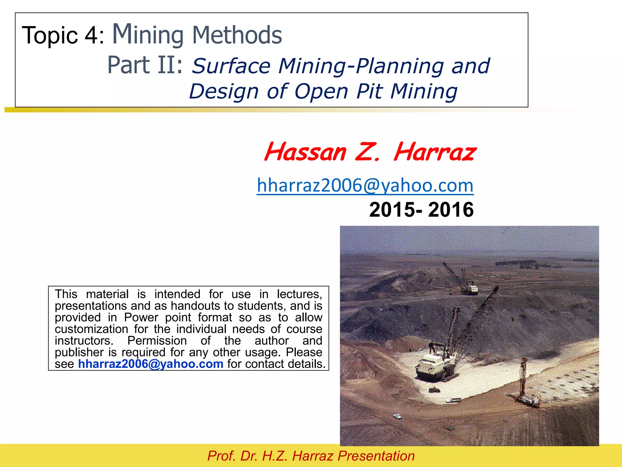
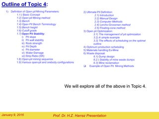
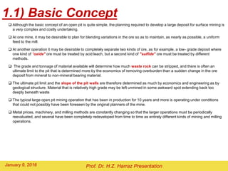
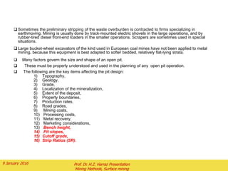
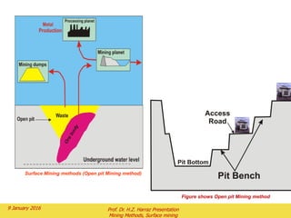
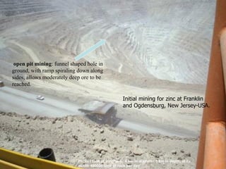
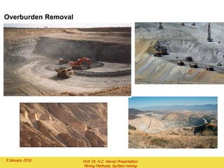
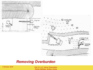
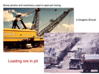
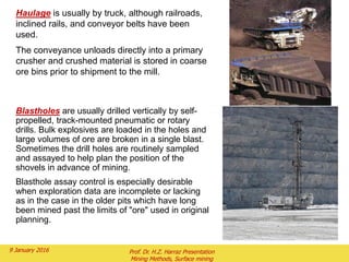
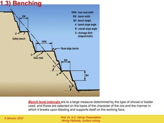
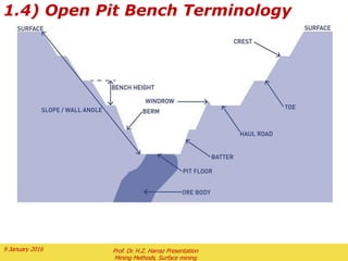
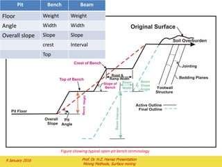
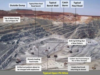
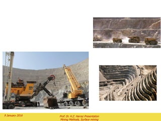
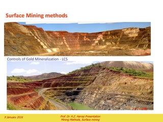
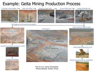
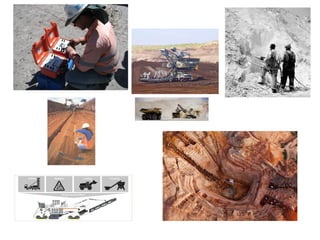
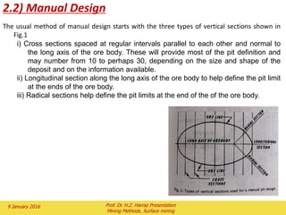
SlideShare a Scribd company logo
1 of 94
This material is intended for use in lectures,
presentations and as handouts to students, and is
provided in Power point format so as to allow
customization for the individual needs of course
instructors. Permission of the author and
publisher is required for any other usage. Please
see hharraz2006@yahoo.com for contact details.
Hassan Z. Harraz
hharraz2006@yahoo.com
2015- 2016
Prof. Dr. H.Z. Harraz Presentation
Topic 6: Mining Methods
Part II: Surface Mining-Planning and
Design of Open Pit Mining
Outline of Topic 6:
1) Definition of Open pit Mining Parameters:
1.1.) Basic Concept
1.2) Open pit Mining method
1.3) Bench
1.4) Open Pit Bench Terminology
1.5) Bench height
1.6) Cutoff grade
1.7) Open Pit Stability:
i) Pit slope
ii) Pit wall stability
iii) Rock strength
iv) Pit Depth
v) Pit diameter
vi) Water Damage
vii) Strip Ratio (SR)
1.8) Open-pit mining sequence
1.9) Various open-pit and orebody configurations
We will explore all of the above in Topic 6.
Prof. Dr. H.Z. Harraz PresentationFebruary 2, 2016
2) Limit or Ultimate Pit Definition:
2.1) Introduction
2.2) Manual Design
2.3) Computer Methods
2.4) Learchs-Grossman method
2.5) Floating cone method
3) Open pit Optimization:
3.1) The management of pit optimization
3.2) A simple example
3.3) The effects of scheduling on the optimal
outline
4) Optimum production scheduling
5) Materials handling Ex-Mine
6) Waste disposal:
6.1) Dump design
6.2 ) Stability of mine waste dumps
6.3) Mine reclamation
 Example of Open Pit Mining Methods
1) Definition of Open Pit
mining parameters
Prof. Dr. H.Z. Harraz PresentationFebruary 2,
3
 Although the basic concept of an open pit is quite simple, the planning required to develop a large deposit for surface mining is
a very complex and costly undertaking.
 At one mine, it may be desirable to plan for blending variations in the ore so as to maintain, as nearly as possible, a uniform
feed to the mill.
 At another operation it may be desirable to completely separate two kinds of ore, as for example, a low- grade deposit where
one kind of "oxide" ore must be treated by acid leach, but a second kind of "sulfide" ore must be treated by different
methods.
 The grade and tonnage of material available will determine how much waste rock can be stripped, and there is often an
ultimate limit to the pit that is determined more by the economics of removing overburden than a sudden change in the ore
deposit from mineral to non-mineral bearing material.
 The ultimate pit limit and the slope of the pit walls are therefore determined as much by economics and engineering as by
geological structure. Material that is relatively high grade may be left unmined in some awkward spot extending back too
deeply beneath waste
 The typical large open pit mining operation that has been in production for 10 years and more is operating under conditions
that could not possibly have been foreseen by the original planners of the mine.
 Metal prices, machinery, and milling methods are constantly changing so that the larger operations must be periodically
reevaluated, and several have been completely redeveloped from time to time as entirely different kinds of mining and milling
operations.
1.1) Basic Concept
Prof. Dr. H.Z. Harraz PresentationFebruary 2, 2016
 Sometimes the preliminary stripping of the waste overburden is contracted to firms specializing in
earthmoving. Mining is usually done by track-mounted electric shovels in the large operations, and by
rubber-tired diesel front-end loaders in the smaller operations. Scrapers are sometimes used in special
situations.
 Large bucket-wheel excavators of the kind used in European coal mines have not been applied to metal
mining, because this equipment is best adapted to softer bedded, relatively flat-lying strata.
 Many factors govern the size and shape of an open pit.
 These must be properly understood and used in the planning of any open pit operation.
 The following are the key items affecting the pit design:
1) Topography,
2) Geology,
3) Grade,
4) Localization of the mineralization,
5) Extent of the deposit,
6) Property boundaries,
7) Production rates,
8) Road grades,
9) Mining costs,
10) Processing costs,
11) Metal recovery,
12) Marketing considerations,
13) Bench height,
14) Pit slopes,
15) Cutoff grade,
16) Strip Ratios (SR).
2 February 2016 Prof. Dr. H.Z. Harraz Presentation
Mining Methods, Surface mining
1.2) Open pit Mining method
 Mine working open to the surface.
 It is usually employed to exploit a near-
surface deposit or one that has a low
stripping ratio.
 Operation designed to extract mineral
deposits that lie close to the surface.
 It is used when the orebody is near the
surface and little overburden (waste
rock) needs to be removed.
 Large hole exposes the ore body.
 Waste rock (overburden) is removed.
 It often necessitates a large capital
investment but generally results in high
productivity, low operating cost, and
good safety conditions.
 2nd cheapest method, but has the
largest environmental impact. Why?
 Funnel shaped hole in ground,
with ramp spiraling down along
sides, allows moderately deep ore
to be reached.
 Waste is first removed, then
the ore is broken and loaded.
 Generally low grade, shallow
ore bodies.
 Non-selective  all high and
low grade zones mined
 Mining rate > 20,000 tons
mined per day (tpd).
 Design issues:
Stripping overburden
Location of haul roads
Equipment  size of trucks
and fleet
Pit slope angle and stability
2 February 2016 Prof. Dr. H.Z. Harraz Presentation
Mining Methods, Surface mining
Classic Open Pits Characterized by
Oval Shape, Benches, spiraling roads
These pits expand without
Moving and generally
Target a vein or steeply
Dipping stock on ore
 Characterized by a series of stair-step like
benches that each act as a working area
 Pit shapes tend to be more configured to
geology of the deposit more than
equipment needs/convenience
 Many pits are ovals
 Fits the geometry of disseminated
metal deposits
 Pits tend to be wider relative to length
 Pits tend not to move like strip mine –
pit develops in place
Surface Mining methods (Open pit Mining method)
2 February 2016 Prof. Dr. H.Z. Harraz Presentation
Mining Methods, Surface mining
Figure shows Open pit Mining method
open pit mining: funnel shaped hole in
ground, with ramp spiraling down along
sides, allows moderately deep ore to be
reached.
Initial mining for zinc at Franklin
and Ogdensburg, New Jersey-USA.
Photo I took at Bingham. 4 km in diameter 1 km in depth, at its
zenith 400000 tons of rock per day
Overburden Removal
2 February 2016 Prof. Dr. H.Z. Harraz Presentation
Mining Methods, Surface mining
Removing Overburden
2 February 2016 Prof. Dr. H.Z. Harraz Presentation
Mining Methods, Surface mining
A Dragline Shovel
Loading ore in pit
Some photos and machinery used in open-pit mining
Haulage is usually by truck, although railroads,
inclined rails, and conveyor belts have been
used.
The conveyance unloads directly into a primary
crusher and crushed material is stored in coarse
ore bins prior to shipment to the mill.
Blastholes are usually drilled vertically by self-
propelled, track-mounted pneumatic or rotary
drills. Bulk explosives are loaded in the holes and
large volumes of ore are broken in a single blast.
Sometimes the drill holes are routinely sampled
and assayed to help plan the position of the
shovels in advance of mining.
Blasthole assay control is especially desirable
when exploration data are incomplete or lacking
as in the case in the older pits which have long
been mined past the limits of "ore" used in original
planning.
2 February 2016 Prof. Dr. H.Z. Harraz Presentation
Mining Methods, Surface mining
Mining Trucks
*To the left is a photograph of a
Liebherr 360 ton (327 metric ton)
haul truck. This unit is powered by a
2750 horse power engine and weighs
443,000 pounds (177 tons) empty...
Crushing in pit
Drilling in pit
2 February 2016 Prof. Dr. H.Z. Harraz Presentation
Mining Methods, Surface mining
2 February 2016 Prof. Dr. H.Z. Harraz Presentation
Mining Methods, Surface mining
1.3) Benching
Bench level intervals are to a large measure determined by the type of shovel or loader
used, and these are selected on the basis of the character of the ore and the manner in
which it breaks upon blasting and supports itself on the working face.
Width of
dozer
Benching Detail
6%
 Benching is used to properly patch or
extend a slope
 Benching is also used to temporarily
support equipment for other work
elements
 Bench detail must be wide enough to
support a dozer % slope in towards the
roadway to resist sliding
1.4) Open Pit Bench Terminology
2 February 2016 Prof. Dr. H.Z. Harraz Presentation
Mining Methods, Surface mining
Trucks parked awaiting the call for their
next loads of ore...!!!
2 February 2016 Prof. Dr. H.Z. Harraz Presentation
Mining Methods, Surface mining
19
Parts of a bench
Terms in Open Pit Benches
Over-all
Pit Slope
Catch Bench
Berm
Crest
Toe
Toe to
Crest Slope
Final Pits Slopes allow
Benches to be wide enough to
Catch rocks and accommodate
A berm. (This is often less than
Than 10 m).
Note: that the toe to Crest slope
is much Steeper than the over-all
Localized single bench failures from a steep toe to crest slope are much more
Tolerable than an over-all pit slope failure over the entire side of a pit.
Bench
 Quarries in strong rock can sustain about 80 to 85o toe to crest slopes.
 Geology determines limits but about 58 to 72o is a common range for toe to crest in open pit metal.
 Over-all slopes often more conservative
 Frequently less than 45o.
 Cannanea Mexico is nearly 60o
Fig.1: Bench cross sections
Fig.2: Example of pit slopes varying in a deposit
2 February 2016 Prof. Dr. H.Z. Harraz Presentation
Mining Methods, Surface mining
Figure showing typical open-pit bench terminology
2 February 2016 Prof. Dr. H.Z. Harraz Presentation
Mining Methods, Surface mining
Pit Bench Beam
Floor Weight Weight
Angle Width Width
Overall slope Slope Slope
crest Interval
Top
2 February 2016
Prof. Dr. H.Z. Harraz Presentation
Mining Methods, Surface mining
23
Typical
Bench Wall
Typical
Haul Road
Typical Non-haul
Road benchOutside Dump
Catch
Berm
Typical Open Pit Mine
Drill rig Drilling Out
a New Pattern
Empty haul truck
returning to shovel
Shovels loading
haul trucks
Drilled out pattern about to
be charged with explosives
Top of Main Ramp
Out of Open Pit
Loaded Haul Truck Going to
Run of Mine Stockpile
2 February 2016 Prof. Dr. H.Z. Harraz Presentation
Mining Methods, Surface mining
1.5) Bench height
The bench height is the vertical distance between each horizontal level of the pit.
 The elements of a bench are illustrated in Fig. 1.
 Unless geological conditions dictate otherwise, all benches should have the same
height.
The height will depend on :
i) The physical characteristics of the deposit;
ii) The degree of selectivity required in separating the ore and waste with the
loading equipment; the rate of production;
iii) The size and type of equipment to meet the production requirements; and
iv) The climatic conditions.
The bench height should be set as high as possible within the limits of the size and
type of equipment selected for the desired production.
The bench should not be so high that it will present safety problems of towering
banks of blasted or un-blasted material.
The bench height in open pit mines will normally range from 15m in large copper
mines to as little as 1 m in uranium mines.
Prof. Dr. H.Z. Harraz PresentationFebruary 2, 2016 5
1.6) Cutoff grade
 Cutoff grade is any grade that for any specific reason is used to separate any two courses of
action.
 The reason used in setting a cutoff grade usually incorporates the economic characteristics of
the project.
 When mining, the operator must make a decision as to whether the next block of material
should be mined and processed, mined and stockpiled, mined (to expose ore) and sent to the
waste dump, or not mined at all.
 The grade of the block is used to make this decision.
 For any block to be deliberately mined, it must pay for the costs of mining, processing, and
marketing. The grade of material that can pay for this(the costing, processing and marketing)
but for no stripping is the breakeven mining cutoff grade.
 A second cutoff grade can be used for blocks that are below the mining cutoff grade and would
not be mined for their own value.
 These blocks may be mined as waste by deeper ore blocks.
 The cost of mining these blocks is paid for by the deeper ore.
 The final destination of these blocks is then only influenced by costs for the blocks once they
have been mined.
 The blocks can be processed at this point if they can pay for just the processing and marketing
costs.
 In mining phase the cutoff grade calculation would include the drilling, blasting, loading, and
hauling costs.
 The processing costs would cover crushing, conveying, grinding, and concentrating costs.
 The marketing costs could include concentrate handling, smelting, refining and transportation.
 Additional direct costs for royalties and taxes would also be included.
 Overhead costs should also be added to the calculation.
 Depreciation is used in the calculation for the purpose of setting the pit size.
Table 1 is the calculation of the mining cutoff
grade for a copper project with the following
parameters:
30 kt/d (33000 st pd) of ore mined for
20years
$300,000,000 capital cost (include
replacement capital)
$1.00 mining cost per ton of ore
$0.95 mining cost per ton of waste
$3.00 processing cost per ton of ore
$1.00 general and administrative (G&A)
cost per ton of ore
$0.75 freight, smelter, and refining (FSR)
cost per kilogram of copper
85% overall copper recovery
Note that
The cutoff grade will increase as the costs increase is shown
in Fig. 8.
The difference between the mining cutoff grade and the
milling cutoff grade is shown in Fig.9.
2 February 2016 Prof. Dr. H.Z. Harraz Presentation
Mining Methods, Surface mining
2 February 2016 Prof. Dr. H.Z. Harraz Presentation
Mining Methods, Surface mining
Geometry of a Working Bench
Shovel
Truck Width
Back-up
Truck
Truck
Turning
radius
Berm width
Shovel
Length
A bench big enough
To accommodate
Equipment working is
Much wider than one
Only intended to catch
Rolling rocks.
Impact of a Working Bench
Over-all
Slope
The over-all slope of the pit is drastically
Reduced if one must accommodate wide
Working benches.
1.7) Open Pit Stability
The following are the key items affecting the
Open Pit Stability:
i) Pit slope
ii) Pit wall stability
iii)Rock strength
iv)Pit Depth
v) Pit diameter
vi)Water Damage
vii)Strip Ratio (SR)
February 2, 2016
Prof. Dr. H.Z. Harraz Presentation
i) Pit Slopes
 The slope of the pit wall is one of the major elements affecting the size and
shape of the pit.
 The pit slope helps determine the amount of waste that must be moved to
mine ore.
 The pit wall needs to remain stable as long as mining activity is in that area.
 The stability of the pit walls should be analyzed as carefully as possible.
 Rock strength, faults, joints, presence of water, and other geologic
information are key factors in the evaluation of the proper slope angle.
 The physical characteristics of the deposit cause the pit slope to change
with rock type, sector location, elevation, or orientation within the pit.
 Pit slopes are cut into benches to aid stability and contain any slope
failures.
 Rock most be stronger than sand so the angle of repose can be larger.
 45° is usually the maximum slope.
 Pit slopes are benched.
• The revenue from ore must pay for the cost of excavating waste from the
pushback and for excavating the ore.
• The slope cannot exceed 45° and remain stable, so at some point it
becomes impossible and/or uneconomic to continue mining.
2 February 2016 Prof. Dr. H.Z. Harraz Presentation
Mining Methods, Surface mining
 Fig. 2 illustrates how the pit slopes may vary in the deposit.
 A proper slope evaluation will give the slope that allows the pit walls to remain stable.
 The pit walls should be set as steep as possible to minimize the strip ratio.
 The pit slope analysis determines the angle to be used between the roads in the pit.
 The overall pit slope used for design must be flatter to allow for the road system in the ultimate pit.
 Fig 3 and Fig 4 show the need to design the pit with a lesser slope to allow for roads:
 Fig. 3 has been designed with a 450 angle for the pit walls.
 The pit in Fig. 4 uses the same pit bottom and the 450 inter-ramp slope between the roads, but, a
road has been added. So the overall pit slope is lesser the inter-ramp slope.
 In the example, almost 50% more tonnage must be moved to mine the same pit bottom.
 In the early design of a pit a lesser pit slope can be used to allow for the road system.
 The pit in Fig. 5 was designed with an overall slope of 380.
 The overall slope to use will depend on the width, grade, and anticipated placement of the road.
 Fig. 6 shows a vertical section of a pit wall from Fig.4.
 The inter-ramp angle is projected from the pit bottom upward to the original ground surface at point B.
 The overall pit slope angle is the angle from the toe of the bottom bench to the crest of the top bench.
 Point A shows the intercept of the overall pit slope angle with the original ground surface.
Pit slopes
2 February 2016 Prof. Dr. H.Z. Harraz Presentation
Mining Methods, Surface mining
Fig.3: Pit designed with
a 45o pit slope
2 February 2016 Prof. Dr. H.Z. Harraz Presentation
Mining Methods, Surface mining
Fig.4: Pit designed with a 45o inter-ramp
slope and a road system
Fig.5: Pit designed with a 38o overall
slope to allow for a 45o inter-ramp slope
and a road system
2 February 2016 Prof. Dr. H.Z. Harraz Presentation
Mining Methods, Surface mining
A surface intercept of pit wall if
roads are included.
B surface intercept of pit wall if
roads are not included
Average pit slope angle
Slope angle
between roads
Original ground surface
2 February 2016 Prof. Dr. H.Z. Harraz Presentation
Mining Methods, Surface mining
Fig.6: Vertical section through a pit wall
• Quarries in strong rock can sustain about 80
to 85 degree toe to crest slopes.
• Geology determines limits but about 58 to
72 degrees is a common range for toe to
crest in open pit metal.
• Over-all slopes often more conservative
 Frequently less than 45 degrees
 Cannanea Mexico is nearly 60
Slope Stability
Function of the natural angle of repose, density, surface and
subsurface water flow
Early stabilization of surfaces is critical i.e. seeding, mulching,
erosion blanket
Upward tracking of slopes slows sheet flow
Eliminate points of concentrated flow using berms or using
slope drains as outlets
Slopes can be “softened” if space permits
Difficult slopes may require riprap, gabions, or other measures
for permanent stabilization
THE SLOPE EFFECT
What happens if we Change
the slope Angle?
What just happened to the overburden volume?
What just happened to our stripping ratio?
Conclusion – Pit Slope Makes a Big Difference in Open Pits
Limiting Slopes
• One limit is geologic – having the pit slide in on you is bad for
investment (and possibly your health if you are at the bottom)
• One exercise commonly taught in rock mechanics courses is
plotting fractures on stereo net
 Illustrates how many fractures are opened up by benches
Daylighted fracture
Offers an opportunity
To slide off.
Non-Daylighted fracture offers little
Risk
Implications for Slope Effect
• In long area strip mines where things broke down to 2 dimensions slope did
not impact stripping ratio
• Here in this static 3D pit geometry the impact is huge
• Obviously having a steeper slope improves economics
Probability of Failure
• Not all daylighted fractures will slip
• Not every non-daylighted fracture will hold
• More major extensive daylighted fractures more likely a major failure is
 One New Mexico mine lost entire pit as slide slipped in over several months
Significance of Failure
• Some small failures will take a few hours to clean up – can risk these to save money
• Larger regional failures are fatal, probably cannot endure much risk
Can tolerate daylighted
Fractures on benches Daylighted fractures on over-all
Pit slope are another matter
The Equipment Considerations
Why benches?
• Benches stop rolling rocks (a rock rolling down 600 ft and hitting you in the head will split your scull
– even if there are no brains)
 Benches act as rock catchers – they need to be wide enough for this – with the aid of a berm (around 10-15
feet)
• Benches match equipment digging height
Woops!
Bigger shovels allow bigger bench
Height – but require bigger trucks
• Flat area on benches provides room for equipment to move
Bigger trucks have bigger turning radius
Truck
Shovel
Plan view of bench work area
Grade Control and Limits on Bench Heights
Usually have to dig whole bench toe to crest:
Cannot select ore.
Some Mining Depends on selecting only best ore for processing:
Can loose selectivity as bench height increases.
Economics and Advantages of Bench Height
Maintaining bench area involves a cost:
• Less bench area = less cost.
• Higher benches are cheaper (usually).
In drilling for blasting it takes time to set up for every
hole drilled:
• Higher benches allow larger more accurate holes.
• Allow greater spacing – uses drill time more effectively.
The Pit Slope Problem
Our Ultimate Pit Was Calculated at Our Final Pit Slope:
 A final pit slope has benches wide enough to catch falling
rock and allow for a road to get equipment out.
 A bench 10 to 15 meters wide will usually catch falling rock
But that may be just barely enough for a truck to drive forward if the
bed drags the highwall and the tire runs over the berm
No room for maneuvering the truck for production.
 A Final Pit Slope cannot account for equipment in operation.
Open-pit slope failure –structural problems
Pre-mining geological structures, particularly fault planes, represent zones of potential
weakness in the rock mass, and are therefore zones of potential slope failure, and should
be taken into account when designing the mine.
Fault planes dipping towards the pit (as shown in the figure) present a greater risk than
faults dipping away from the pit.
Faults planes often provide passage-ways for water movement, and these waters,
through the process of weathering and chemical alteration of minerals, may reduce the
strength of the rocks on either side of the fault plane, and reduce the “coefficient of
friction” along it.
The coefficient of friction (the “traction” or “grip”) along the fault will determine whether
failure and slippage of rock down the fault plane is likely.
The coefficient of friction may change with time:
 as water-flow patterns are affected by mining
 as faults are exposed by the removal of rock, opening fluid pathways into faults
 by the reduction of the mass of the rock located above the fault plane.
2 February 2016 Prof. Dr. H.Z. Harraz Presentation
Mining Methods, Surface mining
ii) Pit Wall Stability
Most orebodies are related to faulting in the earth's crust.
Fault generates stresses in the host rock, rupturing it and causing faults in the rock (Figure 2).
Faults are typically long linear features so that if a circular pit is used to mine an orebody
(Figure 3), it is likely to intersect a fault at two points, which leads to instability in at least
two parts of the pit slope.
Figure 2 Figure 3
 Stable
 Instable:
o Underlying fracture or fault
o Magma
o landslide
2 February 2016 Prof. Dr. H.Z. Harraz Presentation
Mining Methods, Surface mining
o Crack measuring
o Failure warning
o Movement of the walls
Figure 4 shows a landslide that occurred
recently following rain storms. A berm was
created at the base of the slide to protect
the main haul road.
Figure 5 shows a major instability. The
likely cause is an underlying fracture or
fault. The mine wishes to do a major
pushback on this pit wall in order to gain
access to more ore. This could be a
challenging task.
2 February 2016
Prof. Dr. H.Z. Harraz Presentation
Mining Methods, Surface mining
46
Pit slope versus rock strength Pit depth versus pit diameter
Figures from Spitz and Trudinger, 2009
Greater rock strength can support greater bench
heights
resulting in:
i. a steeper pit,
ii. a lower stripping ratio and
iii. less waste rock.
A greater final pit depth requires a larger
diameter pit (assuming rock strength and pit
slope remains unchanged) .
resulting in
i. a higher stripping ratio and
ii. more waste rock.
2 February 2016 Prof. Dr. H.Z. Harraz Presentation
Mining Methods, Surface mining
The Depth Effect
• Note that as a pit goes deeper the stripping ratio
increases until it reaches an economic limit.
• Rule 1 : as slope decreases S.R. increases
• Rule 2 : as depth increases S.R. increases
vi) Water Damage
 Pit most keep dry
 Dewatering also helps to keep the slopes dry and more stable.
Figures shows: In order to keep the pit dry, There are 40 dewatering pumps around
the Cortez pit pumping water out of the ground at a total rate of 30,000 gallons per
minute.
2 February 2016 Prof. Dr. H.Z. Harraz Presentation
Mining Methods, Surface mining
On October 9, 2003, a major landslide occurred, causing perhaps
eight fatalities at the Grasberg Mine, Indonesia (Figures 8 and 9).
What happens when water accumulates?
The accident was related to heavy rainfall and accumulation of
water in the soil layer at the top of the pit.
2 February 2016 Prof. Dr. H.Z. Harraz Presentation
Mining Methods, Surface mining
The failure is thought to be due to very high pore fluid pressures in
the weathered bedrock that created an instability at the interface
between the bedrock and the overlying clays, allowing a slippage to
occur (Speight, 2002).
Open-pit slope failure –case study –groundwater problems
Seepage and mineral
precipitation
Figures modified from Speight, 2002.
A slope failure occurred at the Cleo
Open Pit (Sunrise Dam Gold Mine,
Western Australia) in December 2000.
At the time of failure the pit-floor was
at 100 m depth below surface.
Two critical factors played a role in the
failure:
 The top of the water table is at a very
high level: only 30 m below surface.
 A strong layer of younger clay
sediments overlies weaker weathered
bedrock.
2 February 2016 Prof. Dr. H.Z. Harraz Presentation
Mining Methods, Surface mining
vii) Stripping Ratio
 The ratio is most commonly expressed as:
 Strip Ratio (SR) is the mass of waste to be mined to obtain one unit mass of ore.
Waste (tons)
SR = ----------------
Ore (tons)
 For example, a 3:1 stripping ratio means that mining one cubic meter of ore
will require mining three cubic meters of waste rock.
• Syncrude Tar Sands: SR = 1.2 - 1.4
• Highland Valley: SR ~0.5
• Bagdad mine: SR ~1.2
• Cortez mine: SR = 1.6
Examples:
2 February 2016 Prof. Dr. H.Z. Harraz Presentation
Stripping Ratios
 Stripping ratio is defined as the ratio of the Overburden/Cover Rock / Waste Rock to the orebody.
 One of the ways of describing the geometrical efficiency of a mining operation is through the use
of the term 'Stripping Ratio' (SR).
 It refers to the amount of waste that must be removed to release a given ore quantity.
 Stripping ratio is defined as the ratio of the Overburden/Cover Rock / Waste Rock to the orebody.
 Stripping ratio or strip ratio refers to the ratio of the volume of overburden (or waste
material) required to be handled in order to extract some volume of ore.
 The strip ratio is the ratio of the number of tons of waste that must moved for one ton of ore to be
mined.
 The results of a pit design will determine the tons of waste and ore that the pit contains.
 When speaking of an open pit mine, the term strip ratio is used.
 The ratio of waste and ore for the design will give the average strip ratio for that pit.
Figure 2.8 Open-pit mining sequence (for pipe-like orebody)
2 February 2016 Prof. Dr. H.Z. Harraz Presentation
Mining Methods, Surface mining
1.8) Open-pit mining sequence
1.9) Various open-pit and orebody configurations
Massive deposit, flat terrain (Example
iron-ore or sulphide deposits).
Thick bedded deposits, little overburden, flat
terrain (Example iron ore, coal).
Massive deposit, high relief
(Example copper sulphide).
Dipping seam or bed, flat terrain
(Example anthracite).
Flat lying seam or bed, flat terrain
(Example platinum reefs, coal).
Figure from Hartman and Mutmansky, 2002.
Ore Control Process
Mining / Ore Control (Modular
Mining & Reporting system)
Fusion
Ore Controller
Reporting System
Layout Drill Holes 3D Electronically Log HolesMap Geology with DGPS Model Geology & Ore Zones
Design Ore Blocks
(Manual & MRO)
Reconciliation
CENTRAL DATABASE
Estimate Grade
Controls of Gold Mineralization - NY
2 February 2016 Prof. Dr. H.Z. Harraz Presentation
Mining Methods, Surface mining
Controls of Gold Mineralization (GH Cut1)
2 February 2016 Prof. Dr. H.Z. Harraz Presentation
Mining Methods, Surface mining
Mining Process Flow Chart
• Exploration Geologists (Resource Model):-
i) Drilling:
 Reverse Circulation (RC) Drilling.
 Diamond Core Drilling.
ii) Surface Grab Samples.
iii) Geological Mapping.
• Mine Planning Engineers.
• Mine Production Engineers.
• Mine Geologists:
i) Grade Control Plan & Drilling.
ii) Design Ore Blocks.
• Drill and Blast Engineer.
• Mining Contractor.
2 February 2016 Prof. Dr. H.Z. Harraz Presentation
Mining Methods, Surface mining
Example: Geita Mining Production Process
Ore grade control drilling Blast hole drilling
Ore hauled to run-of-mine (rom) stockpiles
Firing of blast holes Loading of blasted rockCharging of blast holes
Waste material hauled to dump
Waste material tipped onto dump
Reshaping waste dump for rehabilitation
Stockpiled ore loaded into primary crusher
Blast hole drilling
Grade control drilling
Loading of blasted
rock
Nyankanga Pit
Crushed ore stockpile
Prof. Dr. H.Z. Harraz Presentation
Mining Methods, Surface mining
59
2) limits or Ultimate Pit
Definition
2 February 2016 Prof. Dr. H.Z. Harraz Presentation
Mining Methods, Surface mining
2.1) Introduction
 As the first step for long or short-range planning, the limits of the open pit
must be set.
 The limits (ultimate pit) define the amount of ore minable, the metal content,
and the associated amount of waste to be moved during the life of the
operation.
 The size, geometry, and location of the ultimate pit are import in planning
tailings areas, waste dumps, access roads, concentrating plants, and all
other surface facilities.
 Knowledge gained from designing the ultimate pit also aids in guiding future
exploration work.
 The material contained in the pit will meet two objectives.
 A block will not be mined unless it can pay all costs for its mining,
processing, and marketing and for stripping the waste above the block.
 For conservation of resources, any block meeting the first objective will be
included in the pit.
 The result of these objectives is the design that will maximize the total profit
of the pit based on the physical and economic parameters used. As these
parameters change in the future, the pit design may also change.
2 February 2016 Prof. Dr. H.Z. Harraz Presentation
Mining Methods, Surface mining
2.2) Manual Design
2 February 2016 Prof. Dr. H.Z. Harraz Presentation
Mining Methods, Surface mining
The usual method of manual design starts with the three types of vertical sections shown in
Fig.1
i) Cross sections spaced at regular intervals parallel to each other and normal to
the long axis of the ore body. These will provide most of the pit definition and
may number from 10 to perhaps 30, depending on the size and shape of the
deposit and on the information available.
ii) Longitudinal section along the long axis of the ore body to help define the pit limit
at the ends of the ore body.
iii) Radical sections help define the pit limits at the end of the of the ore body.
Each section should show ore grades, surface topography, geology (if
needed to set the pit limits), and structural controls (if needed to set the pit
limits), and any other information that will limit the pit (e.g. ownership
boundaries).
The stripping ratio is used to set the pit limits on each section.
The pit limits are placed on each section independently using the proper pit
slope angle.
The pit limits are placed on the section at a point where the grade of ore can
pay for mining the waste above it.
When the line for the pit limit has been drawn on the section, the grade of the
ore along the line is calculated and the lengths of the ore and waste are
measured.
The ratio of the waste and ore is calculated and compared to the breakeven
stripping ratio for the grade of ore along the pit limit.
If the calculated stripping ratio is less than the allowable stripping ratio,
the pit limit is expanded.
If the calculated stripping ratio is greater, the pit limit is contracted.
This process continues on the section until the pit limit is set at a point where
the calculated stripping ratio and breakeven stripping ratio are equal.
In Fig. 2, the grade on the right side of the pit was estimated to be 0.6% Cu. At
a price of $2.25 per kg of copper, the breakeven stripping ratio from Fig. 3 is
1.3: 1.
2 February 2016 Prof. Dr. H.Z. Harraz Presentation
Mining Methods, Surface mining
The line for the pit limit was found using the required pit slope and
located at the point that gave a waste: ore ratio of 1.3:1. At the limit
On the left side of the section, the pit limit for the 0.7% Cu grade was
similarly determined using a breakeven stripping ratio of 2.7:1. Fig. 2,
Fig. 3
If the grade of ore changed as the pit limit line was moved, the
breakeven stripping ratio to use would also change.
The pit limits are established on the longitudinal section in the same
manner with the same stripping ratio curves.
The pit limits for the radial section are handled with a different stripping
ratio curve, however.
As shown in Fig. 4, the cross sections and the longitudinal section
represent a slice along the pit wall with the base length as the surface
intercept.
The radial section represents a narrow portion of the pit at the base and
much wider portion at the surface intercept.
1
3.1
YZ)(oreofLength
(XY)wasteofLength

2 February 2016 Prof. Dr. H.Z. Harraz Presentation
Mining Methods, Surface mining
2 February 2016 Prof. Dr. H.Z. Harraz Presentation
Mining Methods, Surface mining
The next step in the manual design is to transfer the pit limits from each section to a
single plan map of the deposit.
The elevation and location of the pit bottom and the surface intercepts from each
section are transferred.
The resultant plan map will show a very irregular pattern of the elevation and outline
of the pit bottom and of the surface intercepts.
The bottom must be manually smoothed to conform to the section information.
Starting with the smoothed pit bottom, the engineer will develop the outline for each
bench at the point midway between the bench toe and the crest.
The engineer manually expands the pit from the bottom with the following criteria:
 The breakeven stripping ratios for adjacent sections may need to be
averaged.
 The allowable pit slopes must be obeyed.
 If the road system is designed at the same time, the inter- ramp angle used.
 If the preliminary design does not show the roads, the outline for the
bench midpoints will be based on the flatter overall pit slope that allows for
roads.
 Possible unstable patterns in the pit should be avoided.
Simple geometric patterns on each bench make the designing easier.
When the pit plan has been developed, the results should be reviewed to determine if
the breakeven stripping ratios have been satisfied.
2 February 2016 Prof. Dr. H.Z. Harraz Presentation
Mining Methods, Surface mining
2.3) Computer Methods
 As should be appreciated, the manual design of a pit gets the planning engineer
closely involved with the design and increases the engineer’s knowledge of the
deposit.
 The procedure is cumbersome, though, and is difficult to use on large or
complex deposits.
 Drawback of manual design is that if any of the design parameters change, the
entire process may have to be repeated.
 Another drawback to the method of manual design is that the pit may be well
designed on each section, but, when the sections are joined and the pit is
smoothed, the result may not yield the best overall pit.
2 February 2016 Prof. Dr. H.Z. Harraz Presentation
Mining Methods, Surface mining
2.4) Learchs-Grossman method
The two-dimensional Learchs-Grossman method will design on a
vertical section the pit outline giving the maximum net profit.
The method is appealing because it eliminates the trial-and-error
process of manually designing the pit on each section. The
method is also convenient for computer processing.
The results must still be transferred to a pit plan map and
manually smoothed and checked. The example in Fig. 5
represents a vertical section through a block model of the
deposit.
There are three steps in Learchs-Grossman method:
Step 1: Add the values down each column of blocks and
enter these numbers into the corresponding blocks in Fig. 7.
Step 2: Start with the top block in the left column and work
down each column.
Step 3: Scan the top row for the maximum total value. For
example the optimal pit would have a value of $13. This is the
total net return of the optimal pit. The Fig. 7 shows the pit
outlined on the section.
2 February 2016 Prof. Dr. H.Z. Harraz Presentation
Mining Methods, Surface mining
Return
2.5) Floating cone method
If the grade of the base is above the mining cutoff grade,
the expansion is projected upward to the top level of the
model as in Fig. 8. The resulting cone is formed using the
appropriate pit slope angles. If the total revenues are
greater than the total costs for the blocks in the cone, the
cone has a positive net value and is economic to mine.
A second block is then examined, as shown in Fig. 9. Each
block in the deposit is examined in turn as a base block of a
cone.
3) Open pit Optimization
2 February 2016 Prof. Dr. H.Z. Harraz Presentation
Mining Methods, Surface mining
3.1) The management of pit optimization
The first thing to realize is that any feasible pit outline has a dollar
value which can, in theory, be calculated. To calculate the dollar value
we must decide on a mining sequence and then conceptually,mine
out the pit, progressively accumulating the revenues and costs as we
go.
• The second thing to realize is that in doing this calculation we have,
in effect, allocated a value to every cubic meter or to every block of
rock.
• Current computer optimization techniques attempt to find the feasible
pit outline which has the maximum total dollar value.
2 February 2016 Prof. Dr. H.Z. Harraz Presentation
Mining Methods, Surface mining
3.2) A simple example
 Let us assume that we have a flat topography and a vertical
rectangular ore body of constant grade as is shown in Fig.1. Let us
further assume that the ore body is sufficiently long in strike for end
effects to be ignored.
In this simplified case there are eight possible pit outlines that we can
consider, and the tonnages for these outlines are given in Table 1.
If we assume that ore is worth $2 per ton after all mining and
processing costs have been paid, and that waste costs $1 dollar per
ton to remove, then we obtain the values shown in Table 2 for the
possible pit outlines.
 When plotted against pit tonnage, these values produce the graph in
Fig. 2. with these very simple assumptions the outline with the highest
value is the number five.
2 February 2016 Prof. Dr. H.Z. Harraz Presentation
Mining Methods, Surface mining
3.3) The effects of scheduling on the optimal outline
When we schedule a pit, we plan the sequence in which various
parts of it will be mined and the time interval in which each is to
be mined.
This affects the value of the mine because it determines when
various items of revenue and expenditure will occur. This is
important because the dollar we have today is more valuable to
us than the dollar that we are going to receive or spend in a
year’s time.
In what we will call “worst case” mining, each bench is mined
completely before the next bench is started. Waste at the top of
the outer shells is mined early.
In what we will call “best case” mining, each shell is mined in turn
and thus related ore and waste is mined in approximately the
same time period.
In this case, the optimal pit is usually close to the one obtained by
simple optimization.
Unfortunately if we try to mine each shell separately, mining costs
usually increase and cancel out some of the gains.
2 February 2016 Prof. Dr. H.Z. Harraz Presentation
Mining Methods, Surface mining
In Fig 5, there are three small ore bodies and their
corresponding waste volumes, with their values and costs
shown.
A floating cone program will examine A and will find that the
corresponding cone has a total value of ( 40-20-30) = -10,
and so is not worth mining.
It will then examine B, will find a cone of value( 200-80-
30)=+90 and will convert it to air, leaving the values shown
in Fig. 6.
The cone for C has a total value of (40-50+40-20)= +10, so
that the program mines it.
This should not happen, because some of the value of ore
body A is being used to help pay for the mining of waste (-
50 region) which is below it.
The true optimal pit in this case includes A, B, but not C.
4)Optimum production
scheduling
2 February 2016 Prof. Dr. H.Z. Harraz Presentation
Mining Methods, Surface mining
 The objective of production scheduling is to maximize the net present value and return on
investment that can be derived from the extraction, concentration, and sale of some commodity
from an ore deposit.
 The method and sequence of extraction and the cutoff grade and production strategy will be
affected by the following primary factors.
i) Location and distribution of the ore in respect to topography and elevation;
ii) Mineral types, physical characteristics, and grade/tonnage distribution;
iii) Direct operating expenses associated with mining, processing and converting the
commodity into a salable form;
iv) Initial and replacement capital costs needed to commence and maintain the operation;
v) Indirect costs such as taxes and royalties;
vi) Commodity recovery factors and value;
vii) Market and capital constraints;
viii) political and environmental considerations.
The procedure used to establish the optimal mining schedule can be divided into three stages.
The first defines the extraction order or mining sequence, the second defines a cutoff grade
strategy that varies through time and will be optimal for a given set of production parameters,
and the third defines which combination of production rates of mine, mill, and refinery will be
optimal, within the limits placed by logistical, financial, marketing, and other constraints.
Fig.1 shows the internal phases: typical pit cross section
2 February 2016 Prof. Dr. H.Z. Harraz Presentation
Mining Methods, Surface mining
5) Materials handling Ex-
Mine
2 February 2016 Prof. Dr. H.Z. Harraz Presentation
Mining Methods, Surface mining
 This section will outline design consideration for the development of a hard rock
mine in-pit crushing and conveying system.
 The obvious trend in the nonferrous metals mining industry is toward the mining of
lower grade ores at increasing tonnage rates. With the progressive development of
larger and more efficient milling equipment and alternative processing techniques
the definition of ore, low grade, and waste varies at each operation.
 In the past , the primary crushing, fine crushing, and mill complex tended to be
located in relative close proximity and the majority of the horizontal and vertical
travel distances from the ore source to the crushing station was handled by truck
haulage.
 Due to rising fuel and maintenance costs, economic conditions have forced the pit
designer to minimize the distance the trucks have to transport the ore, and to bring
the primary crusher closer to the source and thus utilize conveyors to perform a
much larger proportion of the ore transport requirements.
Data generated from actual installations have shown that properly designed crushing
and conveying system compare to truck haulage systems as follows:
Significantly lower operating and maintenance costs.
Higher initial capital costs, but with lower present value costs when compared
to the life of the operation.
Improved foul weather operating conditions.
Can provide comparable operating flexibility in certain circumstances.
2 February 2016 Prof. Dr. H.Z. Harraz Presentation
Mining Methods, Surface mining
Table 1 shows the economic benefit comparison in-pit crushing vs. truck
haulage.
Table 2 shows crusher system characteristics desired by mine personnel.
Fig.1 shows the portable crusher and feeder at Sierrita Mine.
Fig.2 shows the schematic of snake sandwick conveyor.
Studies are currently underway to determine what can be done to
improve the technology of in-pit belt conveying.
Consideration is being given to the loop belt concept. This method
works on the principle that depends on the radial forces generated by
putting S curves in the profile of a sandwicked conveyor.
By continually varying the curvature, a lift is achieved within
“geometrical constraints” conforming to specified mine slopes.
( see Fig.2 and 3)
Many high angle conveying concepts have been studied and the
sandwick belt conveyor seems the most promising.
2 February 2016 Prof. Dr. H.Z. Harraz Presentation
Mining Methods, Surface mining
6) Waste disposal
Planning and environmental protection aspects
6.1) Dump design
A waste dump is an area in which a surface mining operation can
dispose of low grade and/or barren material that has to be
removed from the pit to expose higher grade material.
The first step in designing a dump is the selection of a site or sites
that will be suitable to handle the volume of waste rock to be
removed during the mine’s life. Site selection will depend on a
number of factors, the most important of which are:
i) Pit location and size through time.
ii) Topography.
iii) Waste rock volumes by time and source.
iv) Property boundaries.
v) Existing drainage routes.
vi) Reclamation requirements.
vii) Foundation conditions.
viii) Material handling equipment.
Fig. 1 shows a waste dump.
2 February 2016 Prof. Dr. H.Z. Harraz Presentation
Mining Methods, Surface mining
2 February 2016 Prof. Dr. H.Z. Harraz Presentation
Mining Methods, Surface mining
6.2 ) Stability of mine waste dumps
The overall stability of mine waste sumps is depend on a
number of factors such as:
i) Topography of the dump site.
ii) Method of construction.
iii) Geo-technical parameters of mine waste.
iv) Geo-technical parameters of the foundation materials.
v) External forces acting on the dump.
vi) Rate of advance of the dump face.
All of these factors combine in various ways during the life of a
mine waste dump to aid in the stability of the dump or to
contribute to its instability
2 February 2016 Prof. Dr. H.Z. Harraz Presentation
Mining Methods, Surface mining
6.3) Mine reclamation
The purpose of reclamation is to upgrade the physical character of
all or part of a mining area after the mineral values have been
removed and, thereafter, to protect the surrounding
environment from contamination.
In surface mining operations, the three largest areas that are
reclaimed are the mine extraction, the mine waste dump and the
mill tailings areas. This section pertains to the first two items.
If the commodity extracted is a bedded deposit of large extent and
of relatively show depth such as in coal mines, the backfilling of
worked-out areas is a common method of waste disposal and
reclamation. Waste material removed from the initial box cut or
pit either be stockpiled and later transported to fill the final
excavation or the stockpile could be reclaimed and not moved
and the last pit left with little reclamation effort applied.
In most surface operations in commodities other than coal, the
amount of backfilling is restricted of totally impractical.
Therefore, most of the reclamation effort is directed toward the
waste disposal area.
In most surface mining operations, the waste material removed from the pit is deposited
on an adjacent area. The area required for waste disposal is usually equal to or
greater than the pit area because the disturbed waste mater has a greater volume
than in-situ, a lower slope angle than the pit walls, and rarely can the material be
stacked as high as the pit is deep.
In designing waste dumps, particular consideration has to be given to reclamation needs
if the cost is to be minimized.
If the overall slope of the sump face has to be reduced to prevent erosion and to allow
placement of top soils and vegetation, then the dump design should consider terracing
to minimize the amount of material re-handling.
As illustrated in Fig. 2, the cost of re-handling decreases in proportion to the square of
the reciprocal of the number of terraces into which a dump can be broken. Therefore a
dump constructed using three terraces will have only one-ninth the rehandle dozing
costs of a dump of similar height with no terracing.
In order to facilitate reclamation efforts, a berm should be left on each terrace level. This
will lower costs by providing easier access to the faces for equipment spreading
topsoil and for re-vegetation efforts. The berms can also serve as erosion protection
and drainage diversions, if necessary.
The main hazards to a reclamation project will be erosion and leakage of contaminated
waters that will hamper re-vegetation or be hazardous to life. Both of these problems
usually can be corrected through proper drainage control and treatment. Drainage
channels will need to be rock-lined if the channels are to remain in the same location
without excessive bank erosion.
2 February 2016 Prof. Dr. H.Z. Harraz Presentation
Mining Methods, Surface mining
Example of Open Pit
Mining Method
2 February 2016 Prof. Dr. H.Z. Harraz Presentation
Mining Methods, Surface mining
Open-pit mine: Chuquicamata copper mine, Región de Antofagasta, Chile
Locality: Región de Antofagasta, Chile.
Pit dimensions: 4.3 km long x 3 km wide x 850 m deep.
Mining dates: 1915 -present
Total production: 29 million tons of copper to the end of 2007 (excluding Radomiro Tomić production). For
many years it was the mine with the largest annual production in the world, but was recently overtaken by
Minera Escondida (Chile). It remains the mine with the largest total cumulative production.
Production 2007: 896,308 fine metric tons of copper (Codelco, 2007).
Mining cost in 2007: 48.5 US¢ per kg (2006), 73.0 US¢ per kg (2007) (Codelco, 2007).
Employees: 8,420 as of 31st 2007 (Codelco, 2007).
Pre-tax profits: US$ 9.215 billion (2006), US$ 8,451 billion (2007) (Codelco, 2007).
Dust
Slope failure
Benches
Access ramps
http://upload.wikimedia.org/wikipedia/commons/2/2a/Chuquicamata_panora
ma.jpg
2 February 2016 Prof. Dr. H.Z. Harraz Presentation
Mining Methods, Surface mining
Highland Valley Pit, British Columbia
 Porphyry copper
 137,000 tons mined/day (tpd)
 296 Mt reserves:
 0.42% Cu
 0.008% Mo
 Cu, Mo concentrates with gold and silver
By-
product
2 February 2016 Prof. Dr. H.Z. Harraz Presentation
Mining Methods, Surface mining
• The Highland Valley Copper mine, located in British Columbia,
60 km southwest of Kamloops is 97.5% owned by Teck
Cominco.
• Operations at Highland Valley began over 20 years ago by
predecessor companies.
• The open pit contains two in-pit crushers feeding a 12,000
ton/ hour conveying system that delivers ore to stock piles at
the mill.
• The operation is expected to shut down in 2009.
• There is a plan to expand the Valley pit and salvage ore from
the west wall of the Lornex pit.
• If some rock slope stability problems can be overcome in
these pits, the mine life could be extended to 2013.
2 February 2016 Prof. Dr. H.Z. Harraz Presentation
Mining Methods, Surface mining
Example: Palabora, South Africa
 The mine opened in 1964.
 It is a full mine-to-smelter complex.
 Open pit operations ended in 2002.
 The pit used to be the deepest and steepest in the
world.
 The mine is now an underground block-caving
operation with a 20 year mine life.
 Proven reserves are 225 Mt at 0.7% copper.
The Palabora orebody is an igneous, pipe structure containing:-
 Copper
 Magnetite (iron oxide),
 Vermiculite (used for insulation),
 Zirconium,
 Titanium, and
 Uranium.
2 February 2016 Prof. Dr. H.Z. Harraz Presentation
Mining Methods, Surface mining
Example: Tyrone Copper Mine is situated near Silver City, New Mexico, USA
2 February 2016 Prof. Dr. H.Z. Harraz Presentation
Mining Methods, Surface mining
 The open pit Tyrone Copper
Mine is situated near Silver
City, New Mexico, USA.
 Silver City was founded as a
mining town, and the nearby
mining operations of Phelps
Dodge are still the basis for
the local economy.
 In 2006, the Chino and
Tyrone mines produced
125,400 long tons (127,400
t) of copper.
 Mine employment was
1,250, with wages and
salaries totaling $73 million.

More Related Content

What's hot

Basics of openpit mining
Basics of openpit miningBasics of openpit mining
Basics of openpit miningSATYANARAYANA I
 
Sublevel open stopping assignment
Sublevel open stopping assignmentSublevel open stopping assignment
Sublevel open stopping assignmentvirendrasuryawanshi
 
Underground mining method
Underground mining methodUnderground mining method
Underground mining methodSafdar Ali
 
Lecture 2 basic surface mining practise-2
Lecture 2  basic surface mining practise-2Lecture 2  basic surface mining practise-2
Lecture 2 basic surface mining practise-2IDHAMUKI
 
Drilling in Surface Mine.pdf
Drilling in Surface Mine.pdfDrilling in Surface Mine.pdf
Drilling in Surface Mine.pdfBIT Sindri
 
Underground mining methods
Underground mining methodsUnderground mining methods
Underground mining methodsTayyab Anwar
 
Bucket wheel excavator ppt
Bucket wheel excavator pptBucket wheel excavator ppt
Bucket wheel excavator pptknowledge
 
Selection of longwall powered roof support
Selection of longwall powered roof supportSelection of longwall powered roof support
Selection of longwall powered roof supportUlimella Siva Sankar
 
Sampling techniques for mineral deposit
Sampling techniques for mineral depositSampling techniques for mineral deposit
Sampling techniques for mineral depositPramoda Raj
 

What's hot (20)

Basics of openpit mining
Basics of openpit miningBasics of openpit mining
Basics of openpit mining
 
Mechanics of blasting
Mechanics of blasting Mechanics of blasting
Mechanics of blasting
 
Mine waste dump
Mine waste dumpMine waste dump
Mine waste dump
 
Shrinkage and Vertical Crater Retreat Stoping
Shrinkage and Vertical Crater Retreat StopingShrinkage and Vertical Crater Retreat Stoping
Shrinkage and Vertical Crater Retreat Stoping
 
Square set stoping
Square set stopingSquare set stoping
Square set stoping
 
Sublevel open stopping assignment
Sublevel open stopping assignmentSublevel open stopping assignment
Sublevel open stopping assignment
 
Shaft sinking 1
Shaft sinking 1Shaft sinking 1
Shaft sinking 1
 
Underground mining method
Underground mining methodUnderground mining method
Underground mining method
 
Lecture 2 basic surface mining practise-2
Lecture 2  basic surface mining practise-2Lecture 2  basic surface mining practise-2
Lecture 2 basic surface mining practise-2
 
Drilling in Surface Mine.pdf
Drilling in Surface Mine.pdfDrilling in Surface Mine.pdf
Drilling in Surface Mine.pdf
 
Caving Underground Mining Methods (longwall, Sublevel caving, & Block caving)
Caving Underground Mining Methods (longwall, Sublevel caving, &  Block caving)Caving Underground Mining Methods (longwall, Sublevel caving, &  Block caving)
Caving Underground Mining Methods (longwall, Sublevel caving, & Block caving)
 
Lecture 2: Prospecting to Proving
Lecture 2: Prospecting to ProvingLecture 2: Prospecting to Proving
Lecture 2: Prospecting to Proving
 
Introductory mining
Introductory miningIntroductory mining
Introductory mining
 
Underground mining methods
Underground mining methodsUnderground mining methods
Underground mining methods
 
Bucket wheel excavator ppt
Bucket wheel excavator pptBucket wheel excavator ppt
Bucket wheel excavator ppt
 
Sublevel stoping..Underground mining methods
Sublevel stoping..Underground mining methodsSublevel stoping..Underground mining methods
Sublevel stoping..Underground mining methods
 
Selection of longwall powered roof support
Selection of longwall powered roof supportSelection of longwall powered roof support
Selection of longwall powered roof support
 
ore dilution and ore recovery
ore dilution and ore recoveryore dilution and ore recovery
ore dilution and ore recovery
 
Surface mining
Surface miningSurface mining
Surface mining
 
Sampling techniques for mineral deposit
Sampling techniques for mineral depositSampling techniques for mineral deposit
Sampling techniques for mineral deposit
 

Similar to Surface mining planning and design of open pit mining

Topic5-MiningMethods-PartI-Surfacemining.pdf
Topic5-MiningMethods-PartI-Surfacemining.pdfTopic5-MiningMethods-PartI-Surfacemining.pdf
Topic5-MiningMethods-PartI-Surfacemining.pdfShems192009
 
Underground mining system
Underground mining systemUnderground mining system
Underground mining systemSrimontorumpa
 
13surface mining
13surface mining13surface mining
13surface miningArun Kumar
 
First st-mining (1)
First st-mining (1)First st-mining (1)
First st-mining (1)Alex Demidov
 
Support Systems In Cut And Fill Method Of Stoping
Support Systems In Cut And Fill Method Of StopingSupport Systems In Cut And Fill Method Of Stoping
Support Systems In Cut And Fill Method Of Stopingem_vishal
 
Classification of Mining systems mne.pdf
Classification of Mining systems mne.pdfClassification of Mining systems mne.pdf
Classification of Mining systems mne.pdfeaglesniper008
 
Underground mining methods + swot analysis of maddhapara granite
Underground mining methods + swot analysis of maddhapara graniteUnderground mining methods + swot analysis of maddhapara granite
Underground mining methods + swot analysis of maddhapara graniteShahadat Saimon
 
mineral resources and mining
 mineral resources and mining  mineral resources and mining
mineral resources and mining AMIT SAHU
 
Advance Construction equipment's reports
Advance Construction equipment's reports Advance Construction equipment's reports
Advance Construction equipment's reports ssuser061280
 
Trenching & Excavation
Trenching & ExcavationTrenching & Excavation
Trenching & ExcavationShivananda Roy
 
BLOCK CAVING ATRI.ppt
BLOCK CAVING ATRI.pptBLOCK CAVING ATRI.ppt
BLOCK CAVING ATRI.pptAnshul Yadav
 
OIL EXPLORATION | Offshore Drilling Operation| Deilling Rig operation | Types
OIL EXPLORATION | Offshore Drilling Operation| Deilling Rig operation | TypesOIL EXPLORATION | Offshore Drilling Operation| Deilling Rig operation | Types
OIL EXPLORATION | Offshore Drilling Operation| Deilling Rig operation | TypesGaurav Singh Rajput
 

Similar to Surface mining planning and design of open pit mining (20)

Topic5-MiningMethods-PartI-Surfacemining.pdf
Topic5-MiningMethods-PartI-Surfacemining.pdfTopic5-MiningMethods-PartI-Surfacemining.pdf
Topic5-MiningMethods-PartI-Surfacemining.pdf
 
Room and Pillar Mining Method
Room and Pillar Mining MethodRoom and Pillar Mining Method
Room and Pillar Mining Method
 
Cut and Fill Stoping
Cut and Fill StopingCut and Fill Stoping
Cut and Fill Stoping
 
Underground mining system
Underground mining systemUnderground mining system
Underground mining system
 
Topic 7-mining methods-part iii -surface mining- placer mining
Topic 7-mining methods-part iii -surface mining- placer miningTopic 7-mining methods-part iii -surface mining- placer mining
Topic 7-mining methods-part iii -surface mining- placer mining
 
13surface mining
13surface mining13surface mining
13surface mining
 
First st-mining (1)
First st-mining (1)First st-mining (1)
First st-mining (1)
 
geotechnical design for dilution control in underground mining
geotechnical design for dilution control in underground mininggeotechnical design for dilution control in underground mining
geotechnical design for dilution control in underground mining
 
Support Systems In Cut And Fill Method Of Stoping
Support Systems In Cut And Fill Method Of StopingSupport Systems In Cut And Fill Method Of Stoping
Support Systems In Cut And Fill Method Of Stoping
 
Ch2 before
Ch2 beforeCh2 before
Ch2 before
 
Tunneling
TunnelingTunneling
Tunneling
 
Shaft sinking 2
Shaft  sinking 2Shaft  sinking 2
Shaft sinking 2
 
Classification of Mining systems mne.pdf
Classification of Mining systems mne.pdfClassification of Mining systems mne.pdf
Classification of Mining systems mne.pdf
 
Underground mining methods + swot analysis of maddhapara granite
Underground mining methods + swot analysis of maddhapara graniteUnderground mining methods + swot analysis of maddhapara granite
Underground mining methods + swot analysis of maddhapara granite
 
mineral resources and mining
 mineral resources and mining  mineral resources and mining
mineral resources and mining
 
Advance Construction equipment's reports
Advance Construction equipment's reports Advance Construction equipment's reports
Advance Construction equipment's reports
 
Industrial training
Industrial trainingIndustrial training
Industrial training
 
Trenching & Excavation
Trenching & ExcavationTrenching & Excavation
Trenching & Excavation
 
BLOCK CAVING ATRI.ppt
BLOCK CAVING ATRI.pptBLOCK CAVING ATRI.ppt
BLOCK CAVING ATRI.ppt
 
OIL EXPLORATION | Offshore Drilling Operation| Deilling Rig operation | Types
OIL EXPLORATION | Offshore Drilling Operation| Deilling Rig operation | TypesOIL EXPLORATION | Offshore Drilling Operation| Deilling Rig operation | Types
OIL EXPLORATION | Offshore Drilling Operation| Deilling Rig operation | Types
 

More from Geology Department, Faculty of Science, Tanta University

More from Geology Department, Faculty of Science, Tanta University (20)

ESSENTIALS OF IRON ORE DEPOSITS and INDUSTRIES.pdf
ESSENTIALS OF IRON ORE DEPOSITS and INDUSTRIES.pdfESSENTIALS OF IRON ORE DEPOSITS and INDUSTRIES.pdf
ESSENTIALS OF IRON ORE DEPOSITS and INDUSTRIES.pdf
 
Minerals phase transformation by hydrogen reduction.pdf
Minerals phase transformation by hydrogen reduction.pdfMinerals phase transformation by hydrogen reduction.pdf
Minerals phase transformation by hydrogen reduction.pdf
 
Magnetization Roasting of Refractory Iron.pdf
Magnetization Roasting of Refractory Iron.pdfMagnetization Roasting of Refractory Iron.pdf
Magnetization Roasting of Refractory Iron.pdf
 
GLOBAL IRON ORE.pdf
GLOBAL IRON ORE.pdfGLOBAL IRON ORE.pdf
GLOBAL IRON ORE.pdf
 
Ferrous Scrap FUTURE.pdf
Ferrous Scrap  FUTURE.pdfFerrous Scrap  FUTURE.pdf
Ferrous Scrap FUTURE.pdf
 
Pelletizing Process.pdf
Pelletizing Process.pdfPelletizing Process.pdf
Pelletizing Process.pdf
 
Direct Reduced Iron-Production.pdf
Direct Reduced Iron-Production.pdfDirect Reduced Iron-Production.pdf
Direct Reduced Iron-Production.pdf
 
A REVIEW OF IRONMAKING BY DIRECT REDUCTION PROCESSES.pdf
A REVIEW OF IRONMAKING BY DIRECT REDUCTION PROCESSES.pdfA REVIEW OF IRONMAKING BY DIRECT REDUCTION PROCESSES.pdf
A REVIEW OF IRONMAKING BY DIRECT REDUCTION PROCESSES.pdf
 
IRONWORKS.pdf
IRONWORKS.pdfIRONWORKS.pdf
IRONWORKS.pdf
 
ENRICHMENT IRON BY REDUCTION ROASTING-MAGNETIC SEPARATION.pdf
ENRICHMENT IRON BY REDUCTION ROASTING-MAGNETIC SEPARATION.pdfENRICHMENT IRON BY REDUCTION ROASTING-MAGNETIC SEPARATION.pdf
ENRICHMENT IRON BY REDUCTION ROASTING-MAGNETIC SEPARATION.pdf
 
Processes for phosphorus removal from iron ore -.pdf
Processes for phosphorus removal from iron ore -.pdfProcesses for phosphorus removal from iron ore -.pdf
Processes for phosphorus removal from iron ore -.pdf
 
Iron Types-HBI-DRI.pdf
Iron Types-HBI-DRI.pdfIron Types-HBI-DRI.pdf
Iron Types-HBI-DRI.pdf
 
IRON ORE DEPOSITS.pdf
IRON ORE DEPOSITS.pdfIRON ORE DEPOSITS.pdf
IRON ORE DEPOSITS.pdf
 
STEEL INDUSTRY IN EGYPT-Companies and Markets.pdf
STEEL INDUSTRY IN EGYPT-Companies and Markets.pdfSTEEL INDUSTRY IN EGYPT-Companies and Markets.pdf
STEEL INDUSTRY IN EGYPT-Companies and Markets.pdf
 
Cv english-harraz
Cv english-harrazCv english-harraz
Cv english-harraz
 
Rodruin prospecting area conf
Rodruin prospecting area confRodruin prospecting area conf
Rodruin prospecting area conf
 
Crusher; Crushing; and Classification Equipment
Crusher; Crushing; and Classification EquipmentCrusher; Crushing; and Classification Equipment
Crusher; Crushing; and Classification Equipment
 
The garnet group
The garnet groupThe garnet group
The garnet group
 
Hydrothermal alterations
Hydrothermal alterationsHydrothermal alterations
Hydrothermal alterations
 
Lecture 10 textures of ore deposits and associated features
Lecture 10 textures of ore deposits and associated featuresLecture 10 textures of ore deposits and associated features
Lecture 10 textures of ore deposits and associated features
 

Recently uploaded

Procuring digital preservation CAN be quick and painless with our new dynamic...
Procuring digital preservation CAN be quick and painless with our new dynamic...Procuring digital preservation CAN be quick and painless with our new dynamic...
Procuring digital preservation CAN be quick and painless with our new dynamic...Jisc
 
Choosing the Right CBSE School A Comprehensive Guide for Parents
Choosing the Right CBSE School A Comprehensive Guide for ParentsChoosing the Right CBSE School A Comprehensive Guide for Parents
Choosing the Right CBSE School A Comprehensive Guide for Parentsnavabharathschool99
 
Incoming and Outgoing Shipments in 3 STEPS Using Odoo 17
Incoming and Outgoing Shipments in 3 STEPS Using Odoo 17Incoming and Outgoing Shipments in 3 STEPS Using Odoo 17
Incoming and Outgoing Shipments in 3 STEPS Using Odoo 17Celine George
 
Proudly South Africa powerpoint Thorisha.pptx
Proudly South Africa powerpoint Thorisha.pptxProudly South Africa powerpoint Thorisha.pptx
Proudly South Africa powerpoint Thorisha.pptxthorishapillay1
 
ANG SEKTOR NG agrikultura.pptx QUARTER 4
ANG SEKTOR NG agrikultura.pptx QUARTER 4ANG SEKTOR NG agrikultura.pptx QUARTER 4
ANG SEKTOR NG agrikultura.pptx QUARTER 4MiaBumagat1
 
INTRODUCTION TO CATHOLIC CHRISTOLOGY.pptx
INTRODUCTION TO CATHOLIC CHRISTOLOGY.pptxINTRODUCTION TO CATHOLIC CHRISTOLOGY.pptx
INTRODUCTION TO CATHOLIC CHRISTOLOGY.pptxHumphrey A Beña
 
Visit to a blind student's school🧑‍🦯🧑‍🦯(community medicine)
Visit to a blind student's school🧑‍🦯🧑‍🦯(community medicine)Visit to a blind student's school🧑‍🦯🧑‍🦯(community medicine)
Visit to a blind student's school🧑‍🦯🧑‍🦯(community medicine)lakshayb543
 
USPS® Forced Meter Migration - How to Know if Your Postage Meter Will Soon be...
USPS® Forced Meter Migration - How to Know if Your Postage Meter Will Soon be...USPS® Forced Meter Migration - How to Know if Your Postage Meter Will Soon be...
USPS® Forced Meter Migration - How to Know if Your Postage Meter Will Soon be...Postal Advocate Inc.
 
THEORIES OF ORGANIZATION-PUBLIC ADMINISTRATION
THEORIES OF ORGANIZATION-PUBLIC ADMINISTRATIONTHEORIES OF ORGANIZATION-PUBLIC ADMINISTRATION
THEORIES OF ORGANIZATION-PUBLIC ADMINISTRATIONHumphrey A Beña
 
ECONOMIC CONTEXT - PAPER 1 Q3: NEWSPAPERS.pptx
ECONOMIC CONTEXT - PAPER 1 Q3: NEWSPAPERS.pptxECONOMIC CONTEXT - PAPER 1 Q3: NEWSPAPERS.pptx
ECONOMIC CONTEXT - PAPER 1 Q3: NEWSPAPERS.pptxiammrhaywood
 
GRADE 4 - SUMMATIVE TEST QUARTER 4 ALL SUBJECTS
GRADE 4 - SUMMATIVE TEST QUARTER 4 ALL SUBJECTSGRADE 4 - SUMMATIVE TEST QUARTER 4 ALL SUBJECTS
GRADE 4 - SUMMATIVE TEST QUARTER 4 ALL SUBJECTSJoshuaGantuangco2
 
ENGLISH 7_Q4_LESSON 2_ Employing a Variety of Strategies for Effective Interp...
ENGLISH 7_Q4_LESSON 2_ Employing a Variety of Strategies for Effective Interp...ENGLISH 7_Q4_LESSON 2_ Employing a Variety of Strategies for Effective Interp...
ENGLISH 7_Q4_LESSON 2_ Employing a Variety of Strategies for Effective Interp...JhezDiaz1
 
Science 7 Quarter 4 Module 2: Natural Resources.pptx
Science 7 Quarter 4 Module 2: Natural Resources.pptxScience 7 Quarter 4 Module 2: Natural Resources.pptx
Science 7 Quarter 4 Module 2: Natural Resources.pptxMaryGraceBautista27
 
What is Model Inheritance in Odoo 17 ERP
What is Model Inheritance in Odoo 17 ERPWhat is Model Inheritance in Odoo 17 ERP
What is Model Inheritance in Odoo 17 ERPCeline George
 

Recently uploaded (20)

Procuring digital preservation CAN be quick and painless with our new dynamic...
Procuring digital preservation CAN be quick and painless with our new dynamic...Procuring digital preservation CAN be quick and painless with our new dynamic...
Procuring digital preservation CAN be quick and painless with our new dynamic...
 
Choosing the Right CBSE School A Comprehensive Guide for Parents
Choosing the Right CBSE School A Comprehensive Guide for ParentsChoosing the Right CBSE School A Comprehensive Guide for Parents
Choosing the Right CBSE School A Comprehensive Guide for Parents
 
Incoming and Outgoing Shipments in 3 STEPS Using Odoo 17
Incoming and Outgoing Shipments in 3 STEPS Using Odoo 17Incoming and Outgoing Shipments in 3 STEPS Using Odoo 17
Incoming and Outgoing Shipments in 3 STEPS Using Odoo 17
 
Proudly South Africa powerpoint Thorisha.pptx
Proudly South Africa powerpoint Thorisha.pptxProudly South Africa powerpoint Thorisha.pptx
Proudly South Africa powerpoint Thorisha.pptx
 
ANG SEKTOR NG agrikultura.pptx QUARTER 4
ANG SEKTOR NG agrikultura.pptx QUARTER 4ANG SEKTOR NG agrikultura.pptx QUARTER 4
ANG SEKTOR NG agrikultura.pptx QUARTER 4
 
INTRODUCTION TO CATHOLIC CHRISTOLOGY.pptx
INTRODUCTION TO CATHOLIC CHRISTOLOGY.pptxINTRODUCTION TO CATHOLIC CHRISTOLOGY.pptx
INTRODUCTION TO CATHOLIC CHRISTOLOGY.pptx
 
Raw materials used in Herbal Cosmetics.pptx
Raw materials used in Herbal Cosmetics.pptxRaw materials used in Herbal Cosmetics.pptx
Raw materials used in Herbal Cosmetics.pptx
 
TataKelola dan KamSiber Kecerdasan Buatan v022.pdf
TataKelola dan KamSiber Kecerdasan Buatan v022.pdfTataKelola dan KamSiber Kecerdasan Buatan v022.pdf
TataKelola dan KamSiber Kecerdasan Buatan v022.pdf
 
OS-operating systems- ch04 (Threads) ...
OS-operating systems- ch04 (Threads) ...OS-operating systems- ch04 (Threads) ...
OS-operating systems- ch04 (Threads) ...
 
Visit to a blind student's school🧑‍🦯🧑‍🦯(community medicine)
Visit to a blind student's school🧑‍🦯🧑‍🦯(community medicine)Visit to a blind student's school🧑‍🦯🧑‍🦯(community medicine)
Visit to a blind student's school🧑‍🦯🧑‍🦯(community medicine)
 
YOUVE_GOT_EMAIL_PRELIMS_EL_DORADO_2024.pptx
YOUVE_GOT_EMAIL_PRELIMS_EL_DORADO_2024.pptxYOUVE_GOT_EMAIL_PRELIMS_EL_DORADO_2024.pptx
YOUVE_GOT_EMAIL_PRELIMS_EL_DORADO_2024.pptx
 
YOUVE GOT EMAIL_FINALS_EL_DORADO_2024.pptx
YOUVE GOT EMAIL_FINALS_EL_DORADO_2024.pptxYOUVE GOT EMAIL_FINALS_EL_DORADO_2024.pptx
YOUVE GOT EMAIL_FINALS_EL_DORADO_2024.pptx
 
USPS® Forced Meter Migration - How to Know if Your Postage Meter Will Soon be...
USPS® Forced Meter Migration - How to Know if Your Postage Meter Will Soon be...USPS® Forced Meter Migration - How to Know if Your Postage Meter Will Soon be...
USPS® Forced Meter Migration - How to Know if Your Postage Meter Will Soon be...
 
THEORIES OF ORGANIZATION-PUBLIC ADMINISTRATION
THEORIES OF ORGANIZATION-PUBLIC ADMINISTRATIONTHEORIES OF ORGANIZATION-PUBLIC ADMINISTRATION
THEORIES OF ORGANIZATION-PUBLIC ADMINISTRATION
 
ECONOMIC CONTEXT - PAPER 1 Q3: NEWSPAPERS.pptx
ECONOMIC CONTEXT - PAPER 1 Q3: NEWSPAPERS.pptxECONOMIC CONTEXT - PAPER 1 Q3: NEWSPAPERS.pptx
ECONOMIC CONTEXT - PAPER 1 Q3: NEWSPAPERS.pptx
 
GRADE 4 - SUMMATIVE TEST QUARTER 4 ALL SUBJECTS
GRADE 4 - SUMMATIVE TEST QUARTER 4 ALL SUBJECTSGRADE 4 - SUMMATIVE TEST QUARTER 4 ALL SUBJECTS
GRADE 4 - SUMMATIVE TEST QUARTER 4 ALL SUBJECTS
 
ENGLISH 7_Q4_LESSON 2_ Employing a Variety of Strategies for Effective Interp...
ENGLISH 7_Q4_LESSON 2_ Employing a Variety of Strategies for Effective Interp...ENGLISH 7_Q4_LESSON 2_ Employing a Variety of Strategies for Effective Interp...
ENGLISH 7_Q4_LESSON 2_ Employing a Variety of Strategies for Effective Interp...
 
FINALS_OF_LEFT_ON_C'N_EL_DORADO_2024.pptx
FINALS_OF_LEFT_ON_C'N_EL_DORADO_2024.pptxFINALS_OF_LEFT_ON_C'N_EL_DORADO_2024.pptx
FINALS_OF_LEFT_ON_C'N_EL_DORADO_2024.pptx
 
Science 7 Quarter 4 Module 2: Natural Resources.pptx
Science 7 Quarter 4 Module 2: Natural Resources.pptxScience 7 Quarter 4 Module 2: Natural Resources.pptx
Science 7 Quarter 4 Module 2: Natural Resources.pptx
 
What is Model Inheritance in Odoo 17 ERP
What is Model Inheritance in Odoo 17 ERPWhat is Model Inheritance in Odoo 17 ERP
What is Model Inheritance in Odoo 17 ERP
 

Surface mining planning and design of open pit mining

  • 1. This material is intended for use in lectures, presentations and as handouts to students, and is provided in Power point format so as to allow customization for the individual needs of course instructors. Permission of the author and publisher is required for any other usage. Please see hharraz2006@yahoo.com for contact details. Hassan Z. Harraz hharraz2006@yahoo.com 2015- 2016 Prof. Dr. H.Z. Harraz Presentation Topic 6: Mining Methods Part II: Surface Mining-Planning and Design of Open Pit Mining
  • 2. Outline of Topic 6: 1) Definition of Open pit Mining Parameters: 1.1.) Basic Concept 1.2) Open pit Mining method 1.3) Bench 1.4) Open Pit Bench Terminology 1.5) Bench height 1.6) Cutoff grade 1.7) Open Pit Stability: i) Pit slope ii) Pit wall stability iii) Rock strength iv) Pit Depth v) Pit diameter vi) Water Damage vii) Strip Ratio (SR) 1.8) Open-pit mining sequence 1.9) Various open-pit and orebody configurations We will explore all of the above in Topic 6. Prof. Dr. H.Z. Harraz PresentationFebruary 2, 2016 2) Limit or Ultimate Pit Definition: 2.1) Introduction 2.2) Manual Design 2.3) Computer Methods 2.4) Learchs-Grossman method 2.5) Floating cone method 3) Open pit Optimization: 3.1) The management of pit optimization 3.2) A simple example 3.3) The effects of scheduling on the optimal outline 4) Optimum production scheduling 5) Materials handling Ex-Mine 6) Waste disposal: 6.1) Dump design 6.2 ) Stability of mine waste dumps 6.3) Mine reclamation  Example of Open Pit Mining Methods
  • 3. 1) Definition of Open Pit mining parameters Prof. Dr. H.Z. Harraz PresentationFebruary 2, 3
  • 4.  Although the basic concept of an open pit is quite simple, the planning required to develop a large deposit for surface mining is a very complex and costly undertaking.  At one mine, it may be desirable to plan for blending variations in the ore so as to maintain, as nearly as possible, a uniform feed to the mill.  At another operation it may be desirable to completely separate two kinds of ore, as for example, a low- grade deposit where one kind of "oxide" ore must be treated by acid leach, but a second kind of "sulfide" ore must be treated by different methods.  The grade and tonnage of material available will determine how much waste rock can be stripped, and there is often an ultimate limit to the pit that is determined more by the economics of removing overburden than a sudden change in the ore deposit from mineral to non-mineral bearing material.  The ultimate pit limit and the slope of the pit walls are therefore determined as much by economics and engineering as by geological structure. Material that is relatively high grade may be left unmined in some awkward spot extending back too deeply beneath waste  The typical large open pit mining operation that has been in production for 10 years and more is operating under conditions that could not possibly have been foreseen by the original planners of the mine.  Metal prices, machinery, and milling methods are constantly changing so that the larger operations must be periodically reevaluated, and several have been completely redeveloped from time to time as entirely different kinds of mining and milling operations. 1.1) Basic Concept Prof. Dr. H.Z. Harraz PresentationFebruary 2, 2016
  • 5.  Sometimes the preliminary stripping of the waste overburden is contracted to firms specializing in earthmoving. Mining is usually done by track-mounted electric shovels in the large operations, and by rubber-tired diesel front-end loaders in the smaller operations. Scrapers are sometimes used in special situations.  Large bucket-wheel excavators of the kind used in European coal mines have not been applied to metal mining, because this equipment is best adapted to softer bedded, relatively flat-lying strata.  Many factors govern the size and shape of an open pit.  These must be properly understood and used in the planning of any open pit operation.  The following are the key items affecting the pit design: 1) Topography, 2) Geology, 3) Grade, 4) Localization of the mineralization, 5) Extent of the deposit, 6) Property boundaries, 7) Production rates, 8) Road grades, 9) Mining costs, 10) Processing costs, 11) Metal recovery, 12) Marketing considerations, 13) Bench height, 14) Pit slopes, 15) Cutoff grade, 16) Strip Ratios (SR). 2 February 2016 Prof. Dr. H.Z. Harraz Presentation Mining Methods, Surface mining
  • 6. 1.2) Open pit Mining method  Mine working open to the surface.  It is usually employed to exploit a near- surface deposit or one that has a low stripping ratio.  Operation designed to extract mineral deposits that lie close to the surface.  It is used when the orebody is near the surface and little overburden (waste rock) needs to be removed.  Large hole exposes the ore body.  Waste rock (overburden) is removed.  It often necessitates a large capital investment but generally results in high productivity, low operating cost, and good safety conditions.  2nd cheapest method, but has the largest environmental impact. Why?  Funnel shaped hole in ground, with ramp spiraling down along sides, allows moderately deep ore to be reached.  Waste is first removed, then the ore is broken and loaded.  Generally low grade, shallow ore bodies.  Non-selective  all high and low grade zones mined  Mining rate > 20,000 tons mined per day (tpd).  Design issues: Stripping overburden Location of haul roads Equipment  size of trucks and fleet Pit slope angle and stability 2 February 2016 Prof. Dr. H.Z. Harraz Presentation Mining Methods, Surface mining
  • 7. Classic Open Pits Characterized by Oval Shape, Benches, spiraling roads These pits expand without Moving and generally Target a vein or steeply Dipping stock on ore  Characterized by a series of stair-step like benches that each act as a working area  Pit shapes tend to be more configured to geology of the deposit more than equipment needs/convenience  Many pits are ovals  Fits the geometry of disseminated metal deposits  Pits tend to be wider relative to length  Pits tend not to move like strip mine – pit develops in place
  • 8. Surface Mining methods (Open pit Mining method) 2 February 2016 Prof. Dr. H.Z. Harraz Presentation Mining Methods, Surface mining Figure shows Open pit Mining method
  • 9. open pit mining: funnel shaped hole in ground, with ramp spiraling down along sides, allows moderately deep ore to be reached. Initial mining for zinc at Franklin and Ogdensburg, New Jersey-USA. Photo I took at Bingham. 4 km in diameter 1 km in depth, at its zenith 400000 tons of rock per day
  • 10. Overburden Removal 2 February 2016 Prof. Dr. H.Z. Harraz Presentation Mining Methods, Surface mining
  • 11. Removing Overburden 2 February 2016 Prof. Dr. H.Z. Harraz Presentation Mining Methods, Surface mining
  • 12.
  • 13.
  • 14. A Dragline Shovel Loading ore in pit Some photos and machinery used in open-pit mining
  • 15. Haulage is usually by truck, although railroads, inclined rails, and conveyor belts have been used. The conveyance unloads directly into a primary crusher and crushed material is stored in coarse ore bins prior to shipment to the mill. Blastholes are usually drilled vertically by self- propelled, track-mounted pneumatic or rotary drills. Bulk explosives are loaded in the holes and large volumes of ore are broken in a single blast. Sometimes the drill holes are routinely sampled and assayed to help plan the position of the shovels in advance of mining. Blasthole assay control is especially desirable when exploration data are incomplete or lacking as in the case in the older pits which have long been mined past the limits of "ore" used in original planning. 2 February 2016 Prof. Dr. H.Z. Harraz Presentation Mining Methods, Surface mining
  • 16. Mining Trucks *To the left is a photograph of a Liebherr 360 ton (327 metric ton) haul truck. This unit is powered by a 2750 horse power engine and weighs 443,000 pounds (177 tons) empty... Crushing in pit Drilling in pit 2 February 2016 Prof. Dr. H.Z. Harraz Presentation Mining Methods, Surface mining
  • 17. 2 February 2016 Prof. Dr. H.Z. Harraz Presentation Mining Methods, Surface mining 1.3) Benching Bench level intervals are to a large measure determined by the type of shovel or loader used, and these are selected on the basis of the character of the ore and the manner in which it breaks upon blasting and supports itself on the working face. Width of dozer Benching Detail 6%  Benching is used to properly patch or extend a slope  Benching is also used to temporarily support equipment for other work elements  Bench detail must be wide enough to support a dozer % slope in towards the roadway to resist sliding
  • 18. 1.4) Open Pit Bench Terminology 2 February 2016 Prof. Dr. H.Z. Harraz Presentation Mining Methods, Surface mining
  • 19. Trucks parked awaiting the call for their next loads of ore...!!! 2 February 2016 Prof. Dr. H.Z. Harraz Presentation Mining Methods, Surface mining 19 Parts of a bench
  • 20. Terms in Open Pit Benches Over-all Pit Slope Catch Bench Berm Crest Toe Toe to Crest Slope Final Pits Slopes allow Benches to be wide enough to Catch rocks and accommodate A berm. (This is often less than Than 10 m). Note: that the toe to Crest slope is much Steeper than the over-all Localized single bench failures from a steep toe to crest slope are much more Tolerable than an over-all pit slope failure over the entire side of a pit. Bench  Quarries in strong rock can sustain about 80 to 85o toe to crest slopes.  Geology determines limits but about 58 to 72o is a common range for toe to crest in open pit metal.  Over-all slopes often more conservative  Frequently less than 45o.  Cannanea Mexico is nearly 60o
  • 21. Fig.1: Bench cross sections Fig.2: Example of pit slopes varying in a deposit 2 February 2016 Prof. Dr. H.Z. Harraz Presentation Mining Methods, Surface mining
  • 22. Figure showing typical open-pit bench terminology 2 February 2016 Prof. Dr. H.Z. Harraz Presentation Mining Methods, Surface mining Pit Bench Beam Floor Weight Weight Angle Width Width Overall slope Slope Slope crest Interval Top
  • 23. 2 February 2016 Prof. Dr. H.Z. Harraz Presentation Mining Methods, Surface mining 23 Typical Bench Wall Typical Haul Road Typical Non-haul Road benchOutside Dump Catch Berm Typical Open Pit Mine Drill rig Drilling Out a New Pattern Empty haul truck returning to shovel Shovels loading haul trucks Drilled out pattern about to be charged with explosives Top of Main Ramp Out of Open Pit Loaded Haul Truck Going to Run of Mine Stockpile
  • 24. 2 February 2016 Prof. Dr. H.Z. Harraz Presentation Mining Methods, Surface mining
  • 25. 1.5) Bench height The bench height is the vertical distance between each horizontal level of the pit.  The elements of a bench are illustrated in Fig. 1.  Unless geological conditions dictate otherwise, all benches should have the same height. The height will depend on : i) The physical characteristics of the deposit; ii) The degree of selectivity required in separating the ore and waste with the loading equipment; the rate of production; iii) The size and type of equipment to meet the production requirements; and iv) The climatic conditions. The bench height should be set as high as possible within the limits of the size and type of equipment selected for the desired production. The bench should not be so high that it will present safety problems of towering banks of blasted or un-blasted material. The bench height in open pit mines will normally range from 15m in large copper mines to as little as 1 m in uranium mines. Prof. Dr. H.Z. Harraz PresentationFebruary 2, 2016 5
  • 26. 1.6) Cutoff grade  Cutoff grade is any grade that for any specific reason is used to separate any two courses of action.  The reason used in setting a cutoff grade usually incorporates the economic characteristics of the project.  When mining, the operator must make a decision as to whether the next block of material should be mined and processed, mined and stockpiled, mined (to expose ore) and sent to the waste dump, or not mined at all.  The grade of the block is used to make this decision.  For any block to be deliberately mined, it must pay for the costs of mining, processing, and marketing. The grade of material that can pay for this(the costing, processing and marketing) but for no stripping is the breakeven mining cutoff grade.  A second cutoff grade can be used for blocks that are below the mining cutoff grade and would not be mined for their own value.  These blocks may be mined as waste by deeper ore blocks.  The cost of mining these blocks is paid for by the deeper ore.  The final destination of these blocks is then only influenced by costs for the blocks once they have been mined.  The blocks can be processed at this point if they can pay for just the processing and marketing costs.  In mining phase the cutoff grade calculation would include the drilling, blasting, loading, and hauling costs.  The processing costs would cover crushing, conveying, grinding, and concentrating costs.  The marketing costs could include concentrate handling, smelting, refining and transportation.  Additional direct costs for royalties and taxes would also be included.  Overhead costs should also be added to the calculation.  Depreciation is used in the calculation for the purpose of setting the pit size.
  • 27. Table 1 is the calculation of the mining cutoff grade for a copper project with the following parameters: 30 kt/d (33000 st pd) of ore mined for 20years $300,000,000 capital cost (include replacement capital) $1.00 mining cost per ton of ore $0.95 mining cost per ton of waste $3.00 processing cost per ton of ore $1.00 general and administrative (G&A) cost per ton of ore $0.75 freight, smelter, and refining (FSR) cost per kilogram of copper 85% overall copper recovery Note that The cutoff grade will increase as the costs increase is shown in Fig. 8. The difference between the mining cutoff grade and the milling cutoff grade is shown in Fig.9. 2 February 2016 Prof. Dr. H.Z. Harraz Presentation Mining Methods, Surface mining
  • 28. 2 February 2016 Prof. Dr. H.Z. Harraz Presentation Mining Methods, Surface mining
  • 29. Geometry of a Working Bench Shovel Truck Width Back-up Truck Truck Turning radius Berm width Shovel Length A bench big enough To accommodate Equipment working is Much wider than one Only intended to catch Rolling rocks.
  • 30. Impact of a Working Bench Over-all Slope The over-all slope of the pit is drastically Reduced if one must accommodate wide Working benches.
  • 31. 1.7) Open Pit Stability The following are the key items affecting the Open Pit Stability: i) Pit slope ii) Pit wall stability iii)Rock strength iv)Pit Depth v) Pit diameter vi)Water Damage vii)Strip Ratio (SR) February 2, 2016 Prof. Dr. H.Z. Harraz Presentation
  • 32. i) Pit Slopes  The slope of the pit wall is one of the major elements affecting the size and shape of the pit.  The pit slope helps determine the amount of waste that must be moved to mine ore.  The pit wall needs to remain stable as long as mining activity is in that area.  The stability of the pit walls should be analyzed as carefully as possible.  Rock strength, faults, joints, presence of water, and other geologic information are key factors in the evaluation of the proper slope angle.  The physical characteristics of the deposit cause the pit slope to change with rock type, sector location, elevation, or orientation within the pit.  Pit slopes are cut into benches to aid stability and contain any slope failures.  Rock most be stronger than sand so the angle of repose can be larger.  45° is usually the maximum slope.  Pit slopes are benched. • The revenue from ore must pay for the cost of excavating waste from the pushback and for excavating the ore. • The slope cannot exceed 45° and remain stable, so at some point it becomes impossible and/or uneconomic to continue mining. 2 February 2016 Prof. Dr. H.Z. Harraz Presentation Mining Methods, Surface mining
  • 33.  Fig. 2 illustrates how the pit slopes may vary in the deposit.  A proper slope evaluation will give the slope that allows the pit walls to remain stable.  The pit walls should be set as steep as possible to minimize the strip ratio.  The pit slope analysis determines the angle to be used between the roads in the pit.  The overall pit slope used for design must be flatter to allow for the road system in the ultimate pit.  Fig 3 and Fig 4 show the need to design the pit with a lesser slope to allow for roads:  Fig. 3 has been designed with a 450 angle for the pit walls.  The pit in Fig. 4 uses the same pit bottom and the 450 inter-ramp slope between the roads, but, a road has been added. So the overall pit slope is lesser the inter-ramp slope.  In the example, almost 50% more tonnage must be moved to mine the same pit bottom.  In the early design of a pit a lesser pit slope can be used to allow for the road system.  The pit in Fig. 5 was designed with an overall slope of 380.  The overall slope to use will depend on the width, grade, and anticipated placement of the road.  Fig. 6 shows a vertical section of a pit wall from Fig.4.  The inter-ramp angle is projected from the pit bottom upward to the original ground surface at point B.  The overall pit slope angle is the angle from the toe of the bottom bench to the crest of the top bench.  Point A shows the intercept of the overall pit slope angle with the original ground surface. Pit slopes 2 February 2016 Prof. Dr. H.Z. Harraz Presentation Mining Methods, Surface mining
  • 34. Fig.3: Pit designed with a 45o pit slope 2 February 2016 Prof. Dr. H.Z. Harraz Presentation Mining Methods, Surface mining
  • 35. Fig.4: Pit designed with a 45o inter-ramp slope and a road system Fig.5: Pit designed with a 38o overall slope to allow for a 45o inter-ramp slope and a road system 2 February 2016 Prof. Dr. H.Z. Harraz Presentation Mining Methods, Surface mining
  • 36. A surface intercept of pit wall if roads are included. B surface intercept of pit wall if roads are not included Average pit slope angle Slope angle between roads Original ground surface 2 February 2016 Prof. Dr. H.Z. Harraz Presentation Mining Methods, Surface mining Fig.6: Vertical section through a pit wall • Quarries in strong rock can sustain about 80 to 85 degree toe to crest slopes. • Geology determines limits but about 58 to 72 degrees is a common range for toe to crest in open pit metal. • Over-all slopes often more conservative  Frequently less than 45 degrees  Cannanea Mexico is nearly 60
  • 37. Slope Stability Function of the natural angle of repose, density, surface and subsurface water flow Early stabilization of surfaces is critical i.e. seeding, mulching, erosion blanket Upward tracking of slopes slows sheet flow Eliminate points of concentrated flow using berms or using slope drains as outlets Slopes can be “softened” if space permits Difficult slopes may require riprap, gabions, or other measures for permanent stabilization
  • 38. THE SLOPE EFFECT What happens if we Change the slope Angle? What just happened to the overburden volume? What just happened to our stripping ratio? Conclusion – Pit Slope Makes a Big Difference in Open Pits
  • 39. Limiting Slopes • One limit is geologic – having the pit slide in on you is bad for investment (and possibly your health if you are at the bottom) • One exercise commonly taught in rock mechanics courses is plotting fractures on stereo net  Illustrates how many fractures are opened up by benches Daylighted fracture Offers an opportunity To slide off. Non-Daylighted fracture offers little Risk Implications for Slope Effect • In long area strip mines where things broke down to 2 dimensions slope did not impact stripping ratio • Here in this static 3D pit geometry the impact is huge • Obviously having a steeper slope improves economics
  • 40. Probability of Failure • Not all daylighted fractures will slip • Not every non-daylighted fracture will hold • More major extensive daylighted fractures more likely a major failure is  One New Mexico mine lost entire pit as slide slipped in over several months Significance of Failure • Some small failures will take a few hours to clean up – can risk these to save money • Larger regional failures are fatal, probably cannot endure much risk Can tolerate daylighted Fractures on benches Daylighted fractures on over-all Pit slope are another matter
  • 41. The Equipment Considerations Why benches? • Benches stop rolling rocks (a rock rolling down 600 ft and hitting you in the head will split your scull – even if there are no brains)  Benches act as rock catchers – they need to be wide enough for this – with the aid of a berm (around 10-15 feet) • Benches match equipment digging height Woops! Bigger shovels allow bigger bench Height – but require bigger trucks • Flat area on benches provides room for equipment to move Bigger trucks have bigger turning radius Truck Shovel Plan view of bench work area
  • 42. Grade Control and Limits on Bench Heights Usually have to dig whole bench toe to crest: Cannot select ore. Some Mining Depends on selecting only best ore for processing: Can loose selectivity as bench height increases. Economics and Advantages of Bench Height Maintaining bench area involves a cost: • Less bench area = less cost. • Higher benches are cheaper (usually). In drilling for blasting it takes time to set up for every hole drilled: • Higher benches allow larger more accurate holes. • Allow greater spacing – uses drill time more effectively.
  • 43. The Pit Slope Problem Our Ultimate Pit Was Calculated at Our Final Pit Slope:  A final pit slope has benches wide enough to catch falling rock and allow for a road to get equipment out.  A bench 10 to 15 meters wide will usually catch falling rock But that may be just barely enough for a truck to drive forward if the bed drags the highwall and the tire runs over the berm No room for maneuvering the truck for production.  A Final Pit Slope cannot account for equipment in operation.
  • 44. Open-pit slope failure –structural problems Pre-mining geological structures, particularly fault planes, represent zones of potential weakness in the rock mass, and are therefore zones of potential slope failure, and should be taken into account when designing the mine. Fault planes dipping towards the pit (as shown in the figure) present a greater risk than faults dipping away from the pit. Faults planes often provide passage-ways for water movement, and these waters, through the process of weathering and chemical alteration of minerals, may reduce the strength of the rocks on either side of the fault plane, and reduce the “coefficient of friction” along it. The coefficient of friction (the “traction” or “grip”) along the fault will determine whether failure and slippage of rock down the fault plane is likely. The coefficient of friction may change with time:  as water-flow patterns are affected by mining  as faults are exposed by the removal of rock, opening fluid pathways into faults  by the reduction of the mass of the rock located above the fault plane. 2 February 2016 Prof. Dr. H.Z. Harraz Presentation Mining Methods, Surface mining
  • 45. ii) Pit Wall Stability Most orebodies are related to faulting in the earth's crust. Fault generates stresses in the host rock, rupturing it and causing faults in the rock (Figure 2). Faults are typically long linear features so that if a circular pit is used to mine an orebody (Figure 3), it is likely to intersect a fault at two points, which leads to instability in at least two parts of the pit slope. Figure 2 Figure 3  Stable  Instable: o Underlying fracture or fault o Magma o landslide 2 February 2016 Prof. Dr. H.Z. Harraz Presentation Mining Methods, Surface mining o Crack measuring o Failure warning o Movement of the walls
  • 46. Figure 4 shows a landslide that occurred recently following rain storms. A berm was created at the base of the slide to protect the main haul road. Figure 5 shows a major instability. The likely cause is an underlying fracture or fault. The mine wishes to do a major pushback on this pit wall in order to gain access to more ore. This could be a challenging task. 2 February 2016 Prof. Dr. H.Z. Harraz Presentation Mining Methods, Surface mining 46
  • 47. Pit slope versus rock strength Pit depth versus pit diameter Figures from Spitz and Trudinger, 2009 Greater rock strength can support greater bench heights resulting in: i. a steeper pit, ii. a lower stripping ratio and iii. less waste rock. A greater final pit depth requires a larger diameter pit (assuming rock strength and pit slope remains unchanged) . resulting in i. a higher stripping ratio and ii. more waste rock. 2 February 2016 Prof. Dr. H.Z. Harraz Presentation Mining Methods, Surface mining
  • 48. The Depth Effect • Note that as a pit goes deeper the stripping ratio increases until it reaches an economic limit. • Rule 1 : as slope decreases S.R. increases • Rule 2 : as depth increases S.R. increases
  • 49. vi) Water Damage  Pit most keep dry  Dewatering also helps to keep the slopes dry and more stable. Figures shows: In order to keep the pit dry, There are 40 dewatering pumps around the Cortez pit pumping water out of the ground at a total rate of 30,000 gallons per minute. 2 February 2016 Prof. Dr. H.Z. Harraz Presentation Mining Methods, Surface mining
  • 50. On October 9, 2003, a major landslide occurred, causing perhaps eight fatalities at the Grasberg Mine, Indonesia (Figures 8 and 9). What happens when water accumulates? The accident was related to heavy rainfall and accumulation of water in the soil layer at the top of the pit. 2 February 2016 Prof. Dr. H.Z. Harraz Presentation Mining Methods, Surface mining
  • 51. The failure is thought to be due to very high pore fluid pressures in the weathered bedrock that created an instability at the interface between the bedrock and the overlying clays, allowing a slippage to occur (Speight, 2002). Open-pit slope failure –case study –groundwater problems Seepage and mineral precipitation Figures modified from Speight, 2002. A slope failure occurred at the Cleo Open Pit (Sunrise Dam Gold Mine, Western Australia) in December 2000. At the time of failure the pit-floor was at 100 m depth below surface. Two critical factors played a role in the failure:  The top of the water table is at a very high level: only 30 m below surface.  A strong layer of younger clay sediments overlies weaker weathered bedrock. 2 February 2016 Prof. Dr. H.Z. Harraz Presentation Mining Methods, Surface mining
  • 52. vii) Stripping Ratio  The ratio is most commonly expressed as:  Strip Ratio (SR) is the mass of waste to be mined to obtain one unit mass of ore. Waste (tons) SR = ---------------- Ore (tons)  For example, a 3:1 stripping ratio means that mining one cubic meter of ore will require mining three cubic meters of waste rock. • Syncrude Tar Sands: SR = 1.2 - 1.4 • Highland Valley: SR ~0.5 • Bagdad mine: SR ~1.2 • Cortez mine: SR = 1.6 Examples: 2 February 2016 Prof. Dr. H.Z. Harraz Presentation Stripping Ratios  Stripping ratio is defined as the ratio of the Overburden/Cover Rock / Waste Rock to the orebody.  One of the ways of describing the geometrical efficiency of a mining operation is through the use of the term 'Stripping Ratio' (SR).  It refers to the amount of waste that must be removed to release a given ore quantity.  Stripping ratio is defined as the ratio of the Overburden/Cover Rock / Waste Rock to the orebody.  Stripping ratio or strip ratio refers to the ratio of the volume of overburden (or waste material) required to be handled in order to extract some volume of ore.  The strip ratio is the ratio of the number of tons of waste that must moved for one ton of ore to be mined.  The results of a pit design will determine the tons of waste and ore that the pit contains.  When speaking of an open pit mine, the term strip ratio is used.  The ratio of waste and ore for the design will give the average strip ratio for that pit.
  • 53. Figure 2.8 Open-pit mining sequence (for pipe-like orebody) 2 February 2016 Prof. Dr. H.Z. Harraz Presentation Mining Methods, Surface mining 1.8) Open-pit mining sequence
  • 54. 1.9) Various open-pit and orebody configurations Massive deposit, flat terrain (Example iron-ore or sulphide deposits). Thick bedded deposits, little overburden, flat terrain (Example iron ore, coal). Massive deposit, high relief (Example copper sulphide). Dipping seam or bed, flat terrain (Example anthracite). Flat lying seam or bed, flat terrain (Example platinum reefs, coal). Figure from Hartman and Mutmansky, 2002.
  • 55. Ore Control Process Mining / Ore Control (Modular Mining & Reporting system) Fusion Ore Controller Reporting System Layout Drill Holes 3D Electronically Log HolesMap Geology with DGPS Model Geology & Ore Zones Design Ore Blocks (Manual & MRO) Reconciliation CENTRAL DATABASE Estimate Grade
  • 56. Controls of Gold Mineralization - NY 2 February 2016 Prof. Dr. H.Z. Harraz Presentation Mining Methods, Surface mining
  • 57. Controls of Gold Mineralization (GH Cut1) 2 February 2016 Prof. Dr. H.Z. Harraz Presentation Mining Methods, Surface mining
  • 58. Mining Process Flow Chart • Exploration Geologists (Resource Model):- i) Drilling:  Reverse Circulation (RC) Drilling.  Diamond Core Drilling. ii) Surface Grab Samples. iii) Geological Mapping. • Mine Planning Engineers. • Mine Production Engineers. • Mine Geologists: i) Grade Control Plan & Drilling. ii) Design Ore Blocks. • Drill and Blast Engineer. • Mining Contractor. 2 February 2016 Prof. Dr. H.Z. Harraz Presentation Mining Methods, Surface mining
  • 59. Example: Geita Mining Production Process Ore grade control drilling Blast hole drilling Ore hauled to run-of-mine (rom) stockpiles Firing of blast holes Loading of blasted rockCharging of blast holes Waste material hauled to dump Waste material tipped onto dump Reshaping waste dump for rehabilitation Stockpiled ore loaded into primary crusher Blast hole drilling Grade control drilling Loading of blasted rock Nyankanga Pit Crushed ore stockpile Prof. Dr. H.Z. Harraz Presentation Mining Methods, Surface mining 59
  • 60.
  • 61. 2) limits or Ultimate Pit Definition 2 February 2016 Prof. Dr. H.Z. Harraz Presentation Mining Methods, Surface mining
  • 62. 2.1) Introduction  As the first step for long or short-range planning, the limits of the open pit must be set.  The limits (ultimate pit) define the amount of ore minable, the metal content, and the associated amount of waste to be moved during the life of the operation.  The size, geometry, and location of the ultimate pit are import in planning tailings areas, waste dumps, access roads, concentrating plants, and all other surface facilities.  Knowledge gained from designing the ultimate pit also aids in guiding future exploration work.  The material contained in the pit will meet two objectives.  A block will not be mined unless it can pay all costs for its mining, processing, and marketing and for stripping the waste above the block.  For conservation of resources, any block meeting the first objective will be included in the pit.  The result of these objectives is the design that will maximize the total profit of the pit based on the physical and economic parameters used. As these parameters change in the future, the pit design may also change. 2 February 2016 Prof. Dr. H.Z. Harraz Presentation Mining Methods, Surface mining
  • 63. 2.2) Manual Design 2 February 2016 Prof. Dr. H.Z. Harraz Presentation Mining Methods, Surface mining The usual method of manual design starts with the three types of vertical sections shown in Fig.1 i) Cross sections spaced at regular intervals parallel to each other and normal to the long axis of the ore body. These will provide most of the pit definition and may number from 10 to perhaps 30, depending on the size and shape of the deposit and on the information available. ii) Longitudinal section along the long axis of the ore body to help define the pit limit at the ends of the ore body. iii) Radical sections help define the pit limits at the end of the of the ore body.
  • 64. Each section should show ore grades, surface topography, geology (if needed to set the pit limits), and structural controls (if needed to set the pit limits), and any other information that will limit the pit (e.g. ownership boundaries). The stripping ratio is used to set the pit limits on each section. The pit limits are placed on each section independently using the proper pit slope angle. The pit limits are placed on the section at a point where the grade of ore can pay for mining the waste above it. When the line for the pit limit has been drawn on the section, the grade of the ore along the line is calculated and the lengths of the ore and waste are measured. The ratio of the waste and ore is calculated and compared to the breakeven stripping ratio for the grade of ore along the pit limit. If the calculated stripping ratio is less than the allowable stripping ratio, the pit limit is expanded. If the calculated stripping ratio is greater, the pit limit is contracted. This process continues on the section until the pit limit is set at a point where the calculated stripping ratio and breakeven stripping ratio are equal. In Fig. 2, the grade on the right side of the pit was estimated to be 0.6% Cu. At a price of $2.25 per kg of copper, the breakeven stripping ratio from Fig. 3 is 1.3: 1. 2 February 2016 Prof. Dr. H.Z. Harraz Presentation Mining Methods, Surface mining
  • 65. The line for the pit limit was found using the required pit slope and located at the point that gave a waste: ore ratio of 1.3:1. At the limit On the left side of the section, the pit limit for the 0.7% Cu grade was similarly determined using a breakeven stripping ratio of 2.7:1. Fig. 2, Fig. 3 If the grade of ore changed as the pit limit line was moved, the breakeven stripping ratio to use would also change. The pit limits are established on the longitudinal section in the same manner with the same stripping ratio curves. The pit limits for the radial section are handled with a different stripping ratio curve, however. As shown in Fig. 4, the cross sections and the longitudinal section represent a slice along the pit wall with the base length as the surface intercept. The radial section represents a narrow portion of the pit at the base and much wider portion at the surface intercept. 1 3.1 YZ)(oreofLength (XY)wasteofLength  2 February 2016 Prof. Dr. H.Z. Harraz Presentation Mining Methods, Surface mining
  • 66. 2 February 2016 Prof. Dr. H.Z. Harraz Presentation Mining Methods, Surface mining
  • 67. The next step in the manual design is to transfer the pit limits from each section to a single plan map of the deposit. The elevation and location of the pit bottom and the surface intercepts from each section are transferred. The resultant plan map will show a very irregular pattern of the elevation and outline of the pit bottom and of the surface intercepts. The bottom must be manually smoothed to conform to the section information. Starting with the smoothed pit bottom, the engineer will develop the outline for each bench at the point midway between the bench toe and the crest. The engineer manually expands the pit from the bottom with the following criteria:  The breakeven stripping ratios for adjacent sections may need to be averaged.  The allowable pit slopes must be obeyed.  If the road system is designed at the same time, the inter- ramp angle used.  If the preliminary design does not show the roads, the outline for the bench midpoints will be based on the flatter overall pit slope that allows for roads.  Possible unstable patterns in the pit should be avoided. Simple geometric patterns on each bench make the designing easier. When the pit plan has been developed, the results should be reviewed to determine if the breakeven stripping ratios have been satisfied. 2 February 2016 Prof. Dr. H.Z. Harraz Presentation Mining Methods, Surface mining
  • 68. 2.3) Computer Methods  As should be appreciated, the manual design of a pit gets the planning engineer closely involved with the design and increases the engineer’s knowledge of the deposit.  The procedure is cumbersome, though, and is difficult to use on large or complex deposits.  Drawback of manual design is that if any of the design parameters change, the entire process may have to be repeated.  Another drawback to the method of manual design is that the pit may be well designed on each section, but, when the sections are joined and the pit is smoothed, the result may not yield the best overall pit. 2 February 2016 Prof. Dr. H.Z. Harraz Presentation Mining Methods, Surface mining
  • 69. 2.4) Learchs-Grossman method The two-dimensional Learchs-Grossman method will design on a vertical section the pit outline giving the maximum net profit. The method is appealing because it eliminates the trial-and-error process of manually designing the pit on each section. The method is also convenient for computer processing. The results must still be transferred to a pit plan map and manually smoothed and checked. The example in Fig. 5 represents a vertical section through a block model of the deposit. There are three steps in Learchs-Grossman method: Step 1: Add the values down each column of blocks and enter these numbers into the corresponding blocks in Fig. 7. Step 2: Start with the top block in the left column and work down each column. Step 3: Scan the top row for the maximum total value. For example the optimal pit would have a value of $13. This is the total net return of the optimal pit. The Fig. 7 shows the pit outlined on the section. 2 February 2016 Prof. Dr. H.Z. Harraz Presentation Mining Methods, Surface mining
  • 71. 2.5) Floating cone method If the grade of the base is above the mining cutoff grade, the expansion is projected upward to the top level of the model as in Fig. 8. The resulting cone is formed using the appropriate pit slope angles. If the total revenues are greater than the total costs for the blocks in the cone, the cone has a positive net value and is economic to mine. A second block is then examined, as shown in Fig. 9. Each block in the deposit is examined in turn as a base block of a cone.
  • 72. 3) Open pit Optimization 2 February 2016 Prof. Dr. H.Z. Harraz Presentation Mining Methods, Surface mining
  • 73. 3.1) The management of pit optimization The first thing to realize is that any feasible pit outline has a dollar value which can, in theory, be calculated. To calculate the dollar value we must decide on a mining sequence and then conceptually,mine out the pit, progressively accumulating the revenues and costs as we go. • The second thing to realize is that in doing this calculation we have, in effect, allocated a value to every cubic meter or to every block of rock. • Current computer optimization techniques attempt to find the feasible pit outline which has the maximum total dollar value. 2 February 2016 Prof. Dr. H.Z. Harraz Presentation Mining Methods, Surface mining
  • 74. 3.2) A simple example  Let us assume that we have a flat topography and a vertical rectangular ore body of constant grade as is shown in Fig.1. Let us further assume that the ore body is sufficiently long in strike for end effects to be ignored. In this simplified case there are eight possible pit outlines that we can consider, and the tonnages for these outlines are given in Table 1. If we assume that ore is worth $2 per ton after all mining and processing costs have been paid, and that waste costs $1 dollar per ton to remove, then we obtain the values shown in Table 2 for the possible pit outlines.  When plotted against pit tonnage, these values produce the graph in Fig. 2. with these very simple assumptions the outline with the highest value is the number five. 2 February 2016 Prof. Dr. H.Z. Harraz Presentation Mining Methods, Surface mining
  • 75. 3.3) The effects of scheduling on the optimal outline When we schedule a pit, we plan the sequence in which various parts of it will be mined and the time interval in which each is to be mined. This affects the value of the mine because it determines when various items of revenue and expenditure will occur. This is important because the dollar we have today is more valuable to us than the dollar that we are going to receive or spend in a year’s time. In what we will call “worst case” mining, each bench is mined completely before the next bench is started. Waste at the top of the outer shells is mined early. In what we will call “best case” mining, each shell is mined in turn and thus related ore and waste is mined in approximately the same time period. In this case, the optimal pit is usually close to the one obtained by simple optimization. Unfortunately if we try to mine each shell separately, mining costs usually increase and cancel out some of the gains. 2 February 2016 Prof. Dr. H.Z. Harraz Presentation Mining Methods, Surface mining
  • 76. In Fig 5, there are three small ore bodies and their corresponding waste volumes, with their values and costs shown. A floating cone program will examine A and will find that the corresponding cone has a total value of ( 40-20-30) = -10, and so is not worth mining. It will then examine B, will find a cone of value( 200-80- 30)=+90 and will convert it to air, leaving the values shown in Fig. 6. The cone for C has a total value of (40-50+40-20)= +10, so that the program mines it. This should not happen, because some of the value of ore body A is being used to help pay for the mining of waste (- 50 region) which is below it. The true optimal pit in this case includes A, B, but not C.
  • 77. 4)Optimum production scheduling 2 February 2016 Prof. Dr. H.Z. Harraz Presentation Mining Methods, Surface mining
  • 78.  The objective of production scheduling is to maximize the net present value and return on investment that can be derived from the extraction, concentration, and sale of some commodity from an ore deposit.  The method and sequence of extraction and the cutoff grade and production strategy will be affected by the following primary factors. i) Location and distribution of the ore in respect to topography and elevation; ii) Mineral types, physical characteristics, and grade/tonnage distribution; iii) Direct operating expenses associated with mining, processing and converting the commodity into a salable form; iv) Initial and replacement capital costs needed to commence and maintain the operation; v) Indirect costs such as taxes and royalties; vi) Commodity recovery factors and value; vii) Market and capital constraints; viii) political and environmental considerations. The procedure used to establish the optimal mining schedule can be divided into three stages. The first defines the extraction order or mining sequence, the second defines a cutoff grade strategy that varies through time and will be optimal for a given set of production parameters, and the third defines which combination of production rates of mine, mill, and refinery will be optimal, within the limits placed by logistical, financial, marketing, and other constraints. Fig.1 shows the internal phases: typical pit cross section 2 February 2016 Prof. Dr. H.Z. Harraz Presentation Mining Methods, Surface mining
  • 79. 5) Materials handling Ex- Mine 2 February 2016 Prof. Dr. H.Z. Harraz Presentation Mining Methods, Surface mining
  • 80.  This section will outline design consideration for the development of a hard rock mine in-pit crushing and conveying system.  The obvious trend in the nonferrous metals mining industry is toward the mining of lower grade ores at increasing tonnage rates. With the progressive development of larger and more efficient milling equipment and alternative processing techniques the definition of ore, low grade, and waste varies at each operation.  In the past , the primary crushing, fine crushing, and mill complex tended to be located in relative close proximity and the majority of the horizontal and vertical travel distances from the ore source to the crushing station was handled by truck haulage.  Due to rising fuel and maintenance costs, economic conditions have forced the pit designer to minimize the distance the trucks have to transport the ore, and to bring the primary crusher closer to the source and thus utilize conveyors to perform a much larger proportion of the ore transport requirements. Data generated from actual installations have shown that properly designed crushing and conveying system compare to truck haulage systems as follows: Significantly lower operating and maintenance costs. Higher initial capital costs, but with lower present value costs when compared to the life of the operation. Improved foul weather operating conditions. Can provide comparable operating flexibility in certain circumstances. 2 February 2016 Prof. Dr. H.Z. Harraz Presentation Mining Methods, Surface mining
  • 81. Table 1 shows the economic benefit comparison in-pit crushing vs. truck haulage. Table 2 shows crusher system characteristics desired by mine personnel. Fig.1 shows the portable crusher and feeder at Sierrita Mine. Fig.2 shows the schematic of snake sandwick conveyor. Studies are currently underway to determine what can be done to improve the technology of in-pit belt conveying. Consideration is being given to the loop belt concept. This method works on the principle that depends on the radial forces generated by putting S curves in the profile of a sandwicked conveyor. By continually varying the curvature, a lift is achieved within “geometrical constraints” conforming to specified mine slopes. ( see Fig.2 and 3) Many high angle conveying concepts have been studied and the sandwick belt conveyor seems the most promising. 2 February 2016 Prof. Dr. H.Z. Harraz Presentation Mining Methods, Surface mining
  • 82. 6) Waste disposal Planning and environmental protection aspects
  • 83. 6.1) Dump design A waste dump is an area in which a surface mining operation can dispose of low grade and/or barren material that has to be removed from the pit to expose higher grade material. The first step in designing a dump is the selection of a site or sites that will be suitable to handle the volume of waste rock to be removed during the mine’s life. Site selection will depend on a number of factors, the most important of which are: i) Pit location and size through time. ii) Topography. iii) Waste rock volumes by time and source. iv) Property boundaries. v) Existing drainage routes. vi) Reclamation requirements. vii) Foundation conditions. viii) Material handling equipment. Fig. 1 shows a waste dump. 2 February 2016 Prof. Dr. H.Z. Harraz Presentation Mining Methods, Surface mining
  • 84. 2 February 2016 Prof. Dr. H.Z. Harraz Presentation Mining Methods, Surface mining
  • 85. 6.2 ) Stability of mine waste dumps The overall stability of mine waste sumps is depend on a number of factors such as: i) Topography of the dump site. ii) Method of construction. iii) Geo-technical parameters of mine waste. iv) Geo-technical parameters of the foundation materials. v) External forces acting on the dump. vi) Rate of advance of the dump face. All of these factors combine in various ways during the life of a mine waste dump to aid in the stability of the dump or to contribute to its instability 2 February 2016 Prof. Dr. H.Z. Harraz Presentation Mining Methods, Surface mining
  • 86. 6.3) Mine reclamation The purpose of reclamation is to upgrade the physical character of all or part of a mining area after the mineral values have been removed and, thereafter, to protect the surrounding environment from contamination. In surface mining operations, the three largest areas that are reclaimed are the mine extraction, the mine waste dump and the mill tailings areas. This section pertains to the first two items. If the commodity extracted is a bedded deposit of large extent and of relatively show depth such as in coal mines, the backfilling of worked-out areas is a common method of waste disposal and reclamation. Waste material removed from the initial box cut or pit either be stockpiled and later transported to fill the final excavation or the stockpile could be reclaimed and not moved and the last pit left with little reclamation effort applied. In most surface operations in commodities other than coal, the amount of backfilling is restricted of totally impractical. Therefore, most of the reclamation effort is directed toward the waste disposal area.
  • 87. In most surface mining operations, the waste material removed from the pit is deposited on an adjacent area. The area required for waste disposal is usually equal to or greater than the pit area because the disturbed waste mater has a greater volume than in-situ, a lower slope angle than the pit walls, and rarely can the material be stacked as high as the pit is deep. In designing waste dumps, particular consideration has to be given to reclamation needs if the cost is to be minimized. If the overall slope of the sump face has to be reduced to prevent erosion and to allow placement of top soils and vegetation, then the dump design should consider terracing to minimize the amount of material re-handling. As illustrated in Fig. 2, the cost of re-handling decreases in proportion to the square of the reciprocal of the number of terraces into which a dump can be broken. Therefore a dump constructed using three terraces will have only one-ninth the rehandle dozing costs of a dump of similar height with no terracing. In order to facilitate reclamation efforts, a berm should be left on each terrace level. This will lower costs by providing easier access to the faces for equipment spreading topsoil and for re-vegetation efforts. The berms can also serve as erosion protection and drainage diversions, if necessary. The main hazards to a reclamation project will be erosion and leakage of contaminated waters that will hamper re-vegetation or be hazardous to life. Both of these problems usually can be corrected through proper drainage control and treatment. Drainage channels will need to be rock-lined if the channels are to remain in the same location without excessive bank erosion.
  • 88. 2 February 2016 Prof. Dr. H.Z. Harraz Presentation Mining Methods, Surface mining
  • 89. Example of Open Pit Mining Method 2 February 2016 Prof. Dr. H.Z. Harraz Presentation Mining Methods, Surface mining
  • 90. Open-pit mine: Chuquicamata copper mine, Región de Antofagasta, Chile Locality: Región de Antofagasta, Chile. Pit dimensions: 4.3 km long x 3 km wide x 850 m deep. Mining dates: 1915 -present Total production: 29 million tons of copper to the end of 2007 (excluding Radomiro Tomić production). For many years it was the mine with the largest annual production in the world, but was recently overtaken by Minera Escondida (Chile). It remains the mine with the largest total cumulative production. Production 2007: 896,308 fine metric tons of copper (Codelco, 2007). Mining cost in 2007: 48.5 US¢ per kg (2006), 73.0 US¢ per kg (2007) (Codelco, 2007). Employees: 8,420 as of 31st 2007 (Codelco, 2007). Pre-tax profits: US$ 9.215 billion (2006), US$ 8,451 billion (2007) (Codelco, 2007). Dust Slope failure Benches Access ramps http://upload.wikimedia.org/wikipedia/commons/2/2a/Chuquicamata_panora ma.jpg 2 February 2016 Prof. Dr. H.Z. Harraz Presentation Mining Methods, Surface mining
  • 91. Highland Valley Pit, British Columbia  Porphyry copper  137,000 tons mined/day (tpd)  296 Mt reserves:  0.42% Cu  0.008% Mo  Cu, Mo concentrates with gold and silver By- product 2 February 2016 Prof. Dr. H.Z. Harraz Presentation Mining Methods, Surface mining
  • 92. • The Highland Valley Copper mine, located in British Columbia, 60 km southwest of Kamloops is 97.5% owned by Teck Cominco. • Operations at Highland Valley began over 20 years ago by predecessor companies. • The open pit contains two in-pit crushers feeding a 12,000 ton/ hour conveying system that delivers ore to stock piles at the mill. • The operation is expected to shut down in 2009. • There is a plan to expand the Valley pit and salvage ore from the west wall of the Lornex pit. • If some rock slope stability problems can be overcome in these pits, the mine life could be extended to 2013. 2 February 2016 Prof. Dr. H.Z. Harraz Presentation Mining Methods, Surface mining
  • 93. Example: Palabora, South Africa  The mine opened in 1964.  It is a full mine-to-smelter complex.  Open pit operations ended in 2002.  The pit used to be the deepest and steepest in the world.  The mine is now an underground block-caving operation with a 20 year mine life.  Proven reserves are 225 Mt at 0.7% copper. The Palabora orebody is an igneous, pipe structure containing:-  Copper  Magnetite (iron oxide),  Vermiculite (used for insulation),  Zirconium,  Titanium, and  Uranium. 2 February 2016 Prof. Dr. H.Z. Harraz Presentation Mining Methods, Surface mining
  • 94. Example: Tyrone Copper Mine is situated near Silver City, New Mexico, USA 2 February 2016 Prof. Dr. H.Z. Harraz Presentation Mining Methods, Surface mining  The open pit Tyrone Copper Mine is situated near Silver City, New Mexico, USA.  Silver City was founded as a mining town, and the nearby mining operations of Phelps Dodge are still the basis for the local economy.  In 2006, the Chino and Tyrone mines produced 125,400 long tons (127,400 t) of copper.  Mine employment was 1,250, with wages and salaries totaling $73 million.