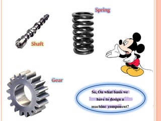
So, On whatbasis we
have to design a
machine component?
6.
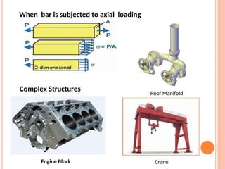
When bar issubjected to axial loading
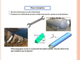
Complex Structures
Roof Manifold
Engine Block Crane
10.
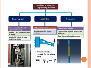
Methods to solveany
Engineering problem
Experimental Analytical Numerical
Time consuming & needs
experimental setup
Atleast 3 to 5 prototypes must
be tested
Applicable only if physical
model is available
Approximate solution
Applicable if physical model is not
available
Real life complicated problems
100% accurate result
Applicable only for simple
problems
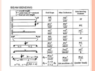
b
B= M
y
I ?
Is this equation is
correct for the above
beam?
12.
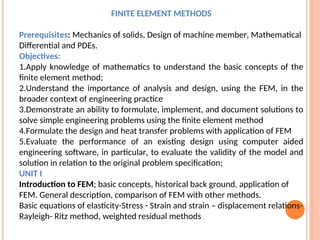
FINITE ELEMENT METHODS
Prerequisites:Mechanics of solids, Design of machine member, Mathematical
Differential and PDEs.
Objectives:
1.Apply knowledge of mathematics to understand the basic concepts of the
finite element method;
2.Understand the importance of analysis and design, using the FEM, in the
broader context of engineering practice
3.Demonstrate an ability to formulate, implement, and document solutions to
solve simple engineering problems using the finite element method
4.Formulate the design and heat transfer problems with application of FEM
5.Evaluate the performance of an existing design using computer aided
engineering software, in particular, to evaluate the validity of the model and
solution in relation to the original problem specification;
UNIT I
Introduction to FEM; basic concepts, historical back ground, application of
FEM. General description, comparison of FEM with other methods.
Basic equations of elasticity-Stress - Strain and strain – displacement relations-
Rayleigh- Ritz method, weighted residual methods
13.
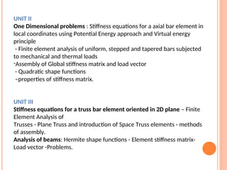
UNIT II
One Dimensionalproblems : Stiffness equations for a axial bar element in
local coordinates using Potential Energy approach and Virtual energy
principle
- Finite element analysis of uniform, stepped and tapered bars subjected
to mechanical and thermal loads
-Assembly of Global stiffness matrix and load vector
- Quadratic shape functions
–properties of stiffness matrix.
UNIT III
Stiffness equations for a truss bar element oriented in 2D plane – Finite
Element Analysis of
Trusses - Plane Truss and introduction of Space Truss elements - methods
of assembly.
Analysis of beams: Hermite shape functions - Element stiffness matrix-
Load vector -Problems.
14.
UNIT IV
2-D problems:CST - Stiffness matrix and load vector – Iso-parametric
element representation - Shape functions - convergence requirements
- Problems.
Two dimensional four node iso-parametric elements – Numerical
integration – Finite element modeling of axisymmetric solids subjected
to Axisymmetric loading with triangular elements - 3-D Elements and
simple applications.
UNIT V
Scalar field problems: I -D Heat conduction - ID fin elements - 2D heat
conduction - analysis of thin plates - Composite slabs - problems.
Dynamic Analysis: Dynamic equations - Lumped and consistent mass
matrices – Eigen Values and Eigen Vectors - mode shapes – modal
analysis for bars and beams.
15.
Outcomes:
At the endof course the students will be able to:
1.Implement numerical methods to solve mechanics of solids and heat transfer
problems.
2.Calculate the stiffness equation for common FEA elements to assemble in to
global equation.
3.Develop FE equations from the mathematical models and apply boundary
conditions to bring it to a solvable form.
4.Determine engineering design parameters for bar, beam structure, 2-D planar
problems and scalar field problems.
5.Calculate the stiffness matrices for fin elements, composite slabs and bars.
TEXT BOOKS:
•The finite element methods in Engineering /S.S. Rao/5th Edition/ Elsevier/2011.
•Introduction to finite elements in engineering/Tirupathi K. Chandrupatla and
Ashok D. Belagundu/3rd Edition/ Prentice –Hall/2002.
REFERENCE BOOKS:
•Finite Element Methods/Alavala/1st Edition /TMH/2008.
•An Introduction to Finite Element Methods/J. N. Reddy /3rd Edition /McGraw-
Hill/2005.
•The Finite element method in engineering science/O.C. Zienkowitz/2nd
Edition/McGraw-Hill/1972.
16.
UNIT I (11Lectures)
Introduction to FEM; basic concepts, historical back ground,
application of FEM. General description, comparison of FEM with other
methods. Basic equations of elasticity-Stress - Strain and strain –
displacement relations- Rayleigh- Ritz method, weighted residual
methods.
Objectives:
1. To introduce the concepts of Mathematical Modeling of Engineering
Problems.
2.To appreciate the use of FEM to a range of Engineering Problems
Outcomes:
1.Upon completion of this course, the students can able to understand
different mathematical Techniques used in FEM analysis and
2.Understand and apply different methods to solve engineering problem
3.Understand the concepts of Nodes and elements
17.
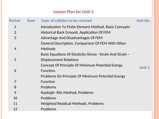
Period Date Topicof syllabus to be covered Unit No.
1 Introduction To Finite Element Method, Basic Concepts
Unit-1
2 Historical Back Ground, Application Of FEM
3 Advantage And Disadvantages Of FEM
4
General Description, Comparison Of FEM With Other
Methods
5
Basic Equations Of Elasticity-Stress - Strain And Strain –
Displacement Relations
6
Concept Of Principle Of Minimum Potential Energy
Function.
7
Problems On Principle Of Minimum Potential Energy
Function
8 Problems
9 Rayleigh- Ritz Method, Problems
10 Problems
11 Weighted Residual Methods, Problems
12 Problems
Lesson Plan for Unit-1
18.
Introduction
The Finite ElementMethod (FEM) is a numerical
technique to find approximate solutions of partial differential
equations. It was originated from the need of solving
complex elasticity and structural analysis problems in Civil,
Mechanical and Aerospace engineering.
Finite element analysis (FEA) involves solution of
engineering problems using computers. Engineering structures
that have complex geometry and loads, are either very difficult to
analyze or have no theoretical solution. However, in FEA, a
structure of this type can be easily analyzed..
19.
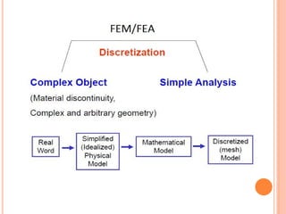
The basic ideain the finite element method is to find the
solution of a complicated problem by replacing it by a simpler
one. Since the actual problem is replaced by a simpler one in
finding the solution,
In the finite element method, the solution region is
considered as built up of many small, interconnected sub
regions called finite elements. As an example of how a
finite element model might be used to represent a
complex geometrical shape are;
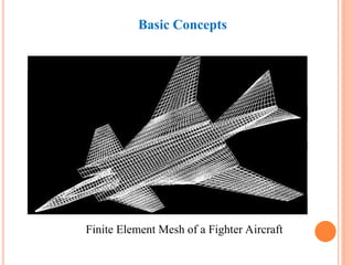
Basic Concepts
20.
The finite elementanalysis can be traced back to the
work by Alexander Hrennikoff (1941) and Richard
Courant (1942). Hrenikoff introduced the framework
method, in which a plane elastic medium was
represented as collections of bars and beams. These
pioneers share one essential characteristic: mesh
discretization of a continuous domain into a set of
discrete sub- domains, usually called elements.
In 1950s, solution of large number of simultaneous
equations became possible because of the digital computer.
In 1960, Ray W. Clough first published a paper using term
“Finite Element Method”.
History of FEM
21.
In 1965, Firstconference on “finite elements” was held.
In 1967, the first book on the “Finite Element Method” was
published by Zienkiewicz and Chung.
In the late 1960s and early 1970s, the FEM was applied to a wide
variety of engineering problems.
In the 1970s, most commercial FEM software
packages (ABAQUS, NASTRAN, ANSYS, etc.) originated.
Interactive FE programs on supercomputer lead to rapid
growth of CAD systems.
22.
In the 1980s,algorithm on electromagnetic applications, fluid
flow and thermal analysis were developed with the use of
FE program.
Engineers can evaluate ways to control the vibrations and extend
the use of flexible, deployable structures in space using FE and
other methods in the 1990s. Trends to solve fully coupled
solution of fluid flows with structural interactions, bio-
mechanics related problems with a higher level of accuracy were
observed in this decade.
Definition of FEM
TheFEM is defined as “it is numerical analysis technique used to obtain
Approximate solution to differential or PDE’s of a wide variety of
Engineering problem”.
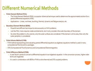
Different types of Numerical Method
1. Finite Approximating Method
2. Finite Difference Method
3. Finite element method
28.
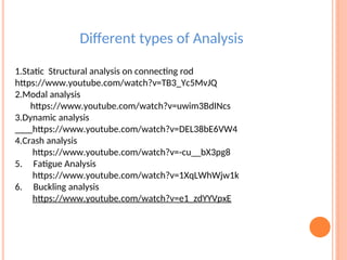
Different types ofAnalysis
1.Static Structural analysis on connecting rod
https://www.youtube.com/watch?v=TB3_Yc5MvJQ
2.Modal analysis
https://www.youtube.com/watch?v=uwim3BdINcs
3.Dynamic analysis
https://www.youtube.com/watch?v=DEL38bE6VW4
4.Crash analysis
https://www.youtube.com/watch?v=-cu__bX3pg8
5. Fatigue Analysis
https://www.youtube.com/watch?v=1XqLWhWjw1k
6. Buckling analysis
https://www.youtube.com/watch?v=e1_zdYYVpxE
29.
Advantages of FiniteElement Method
1.Modeling of complex geometries and irregular shapes are easier as
varieties of finite elements are available for discretization of domain.
2.Boundary conditions can be easily incorporated in FEM.
3.Different types of material properties can be easily accommodated in
modeling from element to element or even within an element.
4.Higher order elements may be implemented.
5.FEM is simple, compact and result-oriented and hence widely popular
among engineering community.
6.Availability of large number of computer software packages and literature
makes FEM a versatile and powerful numerical method.
30.
Disadvantages of FiniteElement Method
1.Large amount of data is required as input for the mesh used in terms
of nodal connectivity and other parameters depending on the
problem.
2.It requires a digital computer and fairly extensive
3.It requires longer execution time compared with FEM.
4.Output result will vary considerably.
36.
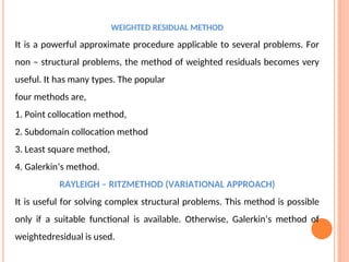
WEIGHTED RESIDUAL METHOD
Itis a powerful approximate procedure applicable to several problems. For
non – structural problems, the method of weighted residuals becomes very
useful. It has many types. The popular
four methods are,
1. Point collocation method,
2. Subdomain collocation method
3. Least square method,
4. Galerkin’s method.
RAYLEIGH – RITZMETHOD (VARIATIONAL APPROACH)
It is useful for solving complex structural problems. This method is possible
only if a suitable functional is available. Otherwise, Galerkin’s method of
weightedresidual is used.