Download to read offline

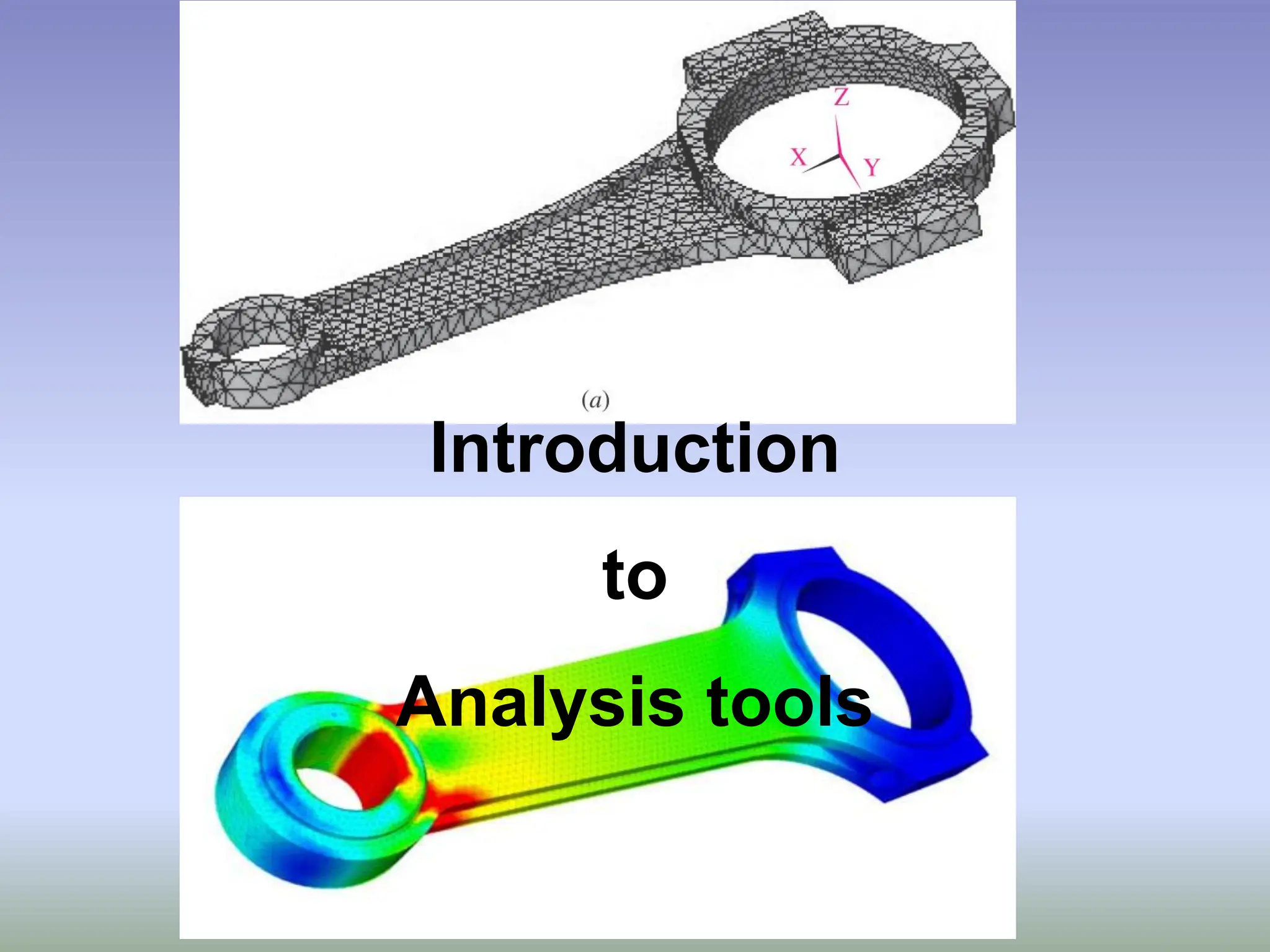
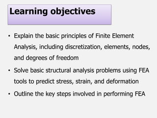
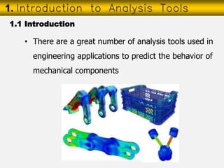
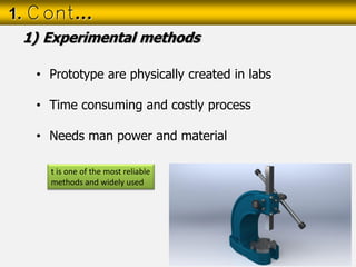
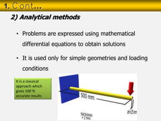
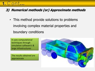
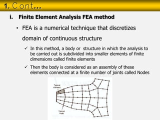
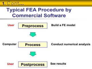
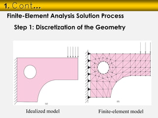
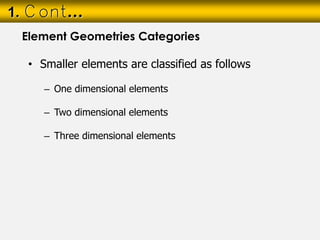
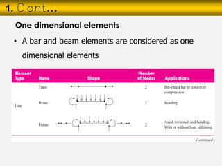
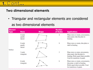
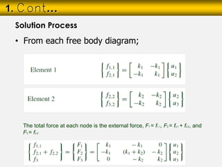
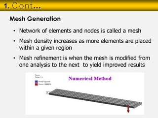
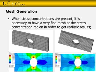


The document provides an introduction to finite element analysis (FEA) and its role in solving structural analysis problems in engineering. It outlines various analysis methods including experimental, analytical, and numerical methods, with a focus on FEA as a numerical technique that divides structures into finite elements. Additionally, it details the general steps and considerations involved in the FEA process, such as mesh generation, load applications, and boundary conditions.


