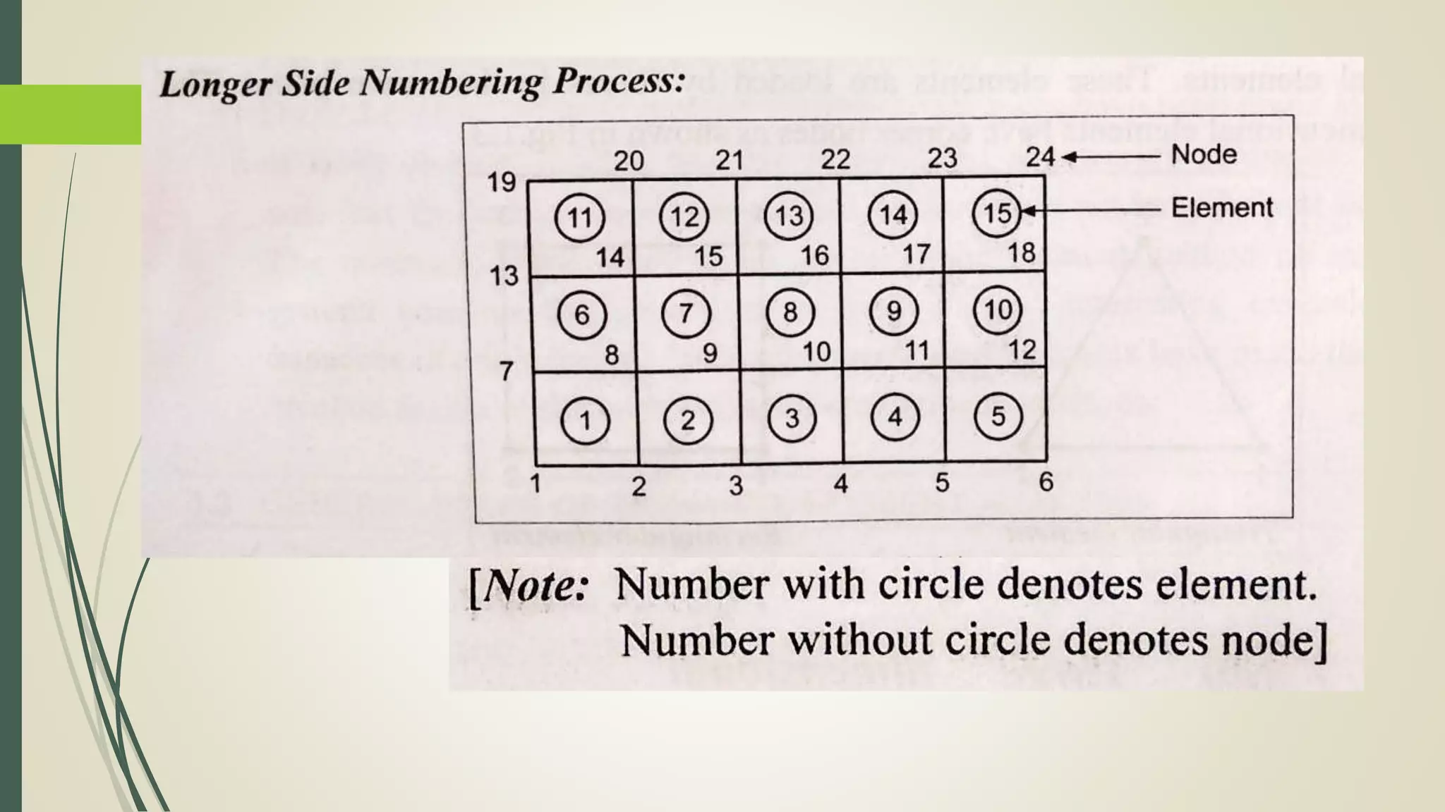
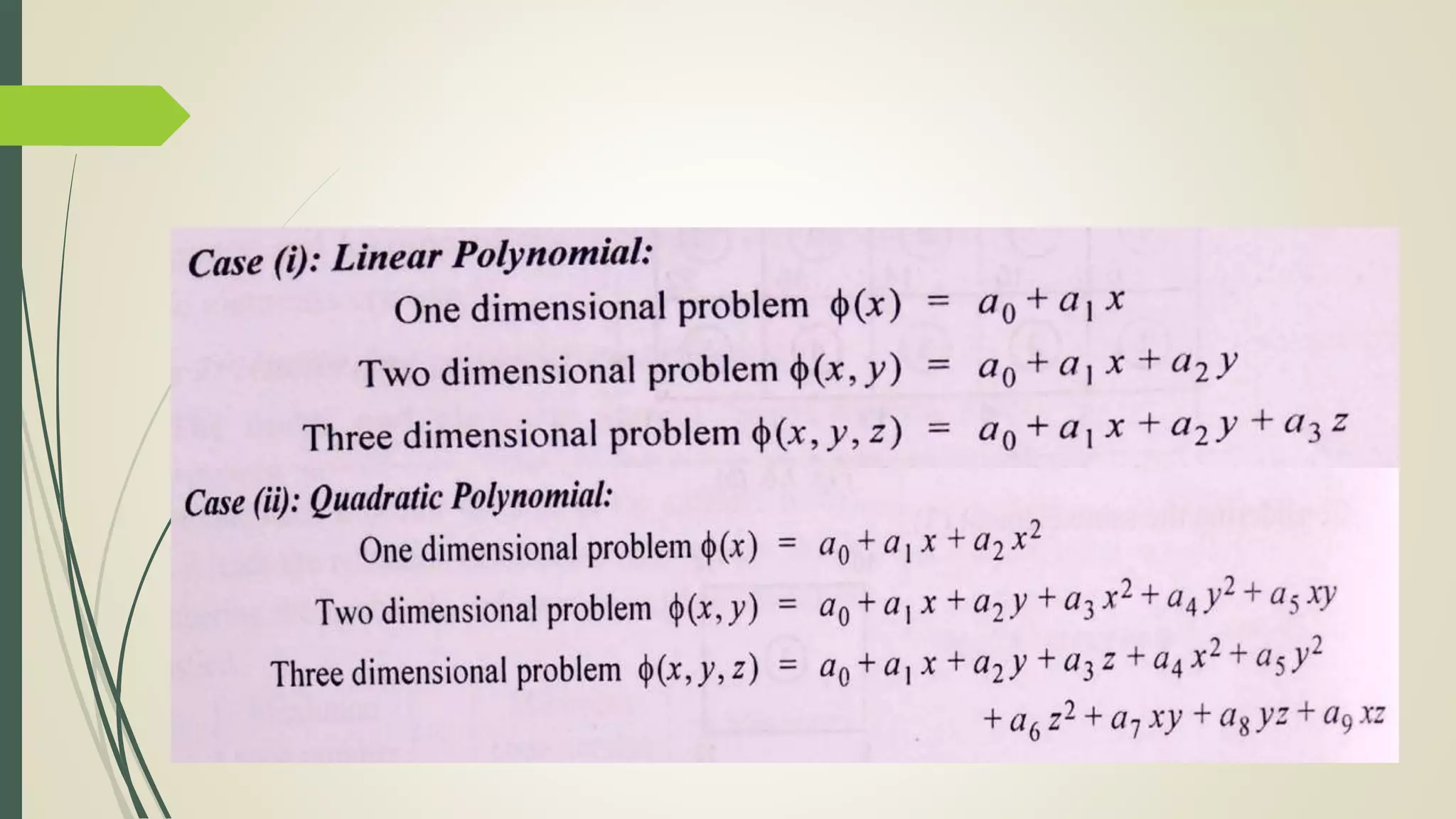
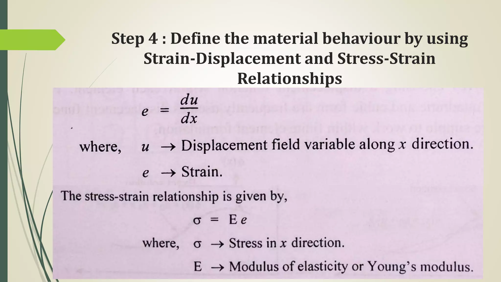
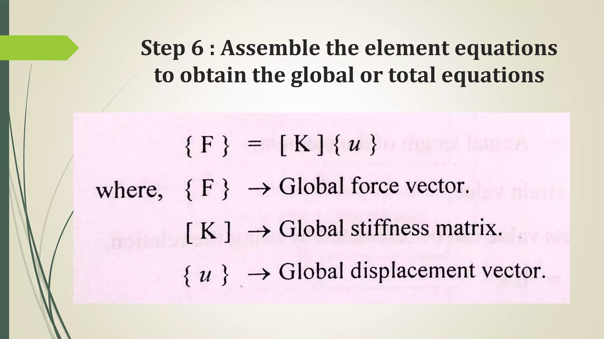
FINITE ELEMENT ANALYSIS
UNIT I - INTRODUCTION
 Historical Background – Mathematical Modeling of field
problems in Engineering – Governing Equations – Discrete and
continuous models – Boundary, Initial and Eigen Value problems
– Weighted Residual Methods – Variational Formulation of
Boundary Value Problems – Ritz Technique – Basic concepts of
the Finite Element Method.
Method of Engineering Analysis
Experimental methods
Analytical methods
Numerical methods (or) Approximate methods
Experimental methods
Prototype can be used
Time consuming and costly process
Needs man power and material
Analytical methods
Problems are expressed by mathematical differential
equations.
It is used only for simple geometries and loading
conditions.
Numerical methods (or)
Approximate methods
Problems involving complex material properties and
boundary conditions.
The following three methods are coming under
numerical solutions.
Functional Approximation
Finite Difference Method (FDM)
Finite Element Method (FEA)
Finite Element Method (FEA)
Finite element method is a numerical method for solving
problems of engineering and mathematical physics.
In this method, a body or structure in which the analysis to
be carried out is subdivided into smaller elements of finite
dimensions called finite elements. Then the body is
considered as an assembly of these elements connected at a
finite number of joints called Nodes.
The properties of each type of finite element is obtained
and assembled together and solved as whole to get
solution.
This method extensively used in the field of structural
mechanics, fluid mechanics , heat transfer, mass transfer,
electric and magnetic fields problems
Based on application, finite element problems are
classified as follows
Structural Problems
Stress and Strain in each element can be calculated
Non-structural Problems
Temperature (or) Fluid pressure at each nodal point is
obtained
General Steps of the Finite Element
Analysis
The following two general methods are associated with
the FEA.
Force Method : Internal forces are considered as the
unknowns of the problem
Displacement or stiffness method : Displacement of the
nodes are considered as the unknowns of the problem.
Step 1 : Discretization of structure
The art of subdividing a structure into a convenient
number of smaller elements is known as discretization.
Smaller elements are classified as follows
One dimensional elements
Two dimensional elements
Three dimensional elements
Axis symmetric elements
One dimensional elements
A bar and beam elements are considered as one
dimensional elements.
The simplest line element also known as linear element
has two nodes, one at each end as shown in figure.
Two dimensional elements
Triangular and rectangular elements are considered as
two dimensional elements.
Three dimensional elements
The most common three dimensional elements are
tetrahedral and hexahedral (Brick) elements.
Axis symmetric elements
The axis symmetric element is developed by rotating a
triangle or quadrilateral about a fixed axis located in
the plane of the element through 360°.
Step 2 : Numbering of Nodes and
Elements
The nodes and elements should be numbered after
discretization process. The numbering process is most
important since it decide the size of the stiffness matrix
and it leads the reduction of memory requirement.
Step 3 : Selection of a Displacement
Function or Interpolation Function
Step 4 : Define the material behaviour by using
Strain-Displacement and Stress-Strain
Relationships
Step 5 : Derivation of element stiffness
matrix and equations
Step 6 : Assemble the element equations
to obtain the global or total equations
Step 7 : Applying Boundary Conditions
From the above equation, Global stiffness matrix is a
singular matrix. Boundary conditions are applied in
that matrix.
Step 8 : Solution for the unknown
displacements
The unknown displacements {u} are calculated by
using Gaussian elimination method or Gauss Seidel
method.
Step 9 : Computation of the element strains
and stresses from the nodal displacements
Step 10 : Interpret the results
Analysis and evaluation of the solution results is
referred to as post processing. Post processor
computer programs help the user to interpret the
results by displaying them in graphical form.
Discretization
Introduction
Discretization
The art of subdividing a structure into a convenient
number of smaller components is known as
Discretization. These smaller components are then put
together.
The process of uniting the various elements together is
called Assemblage. The assemblage of such elements
then represents the original body.
Discretization can be classified as follows
Natural
Artificial (Continuum)
Natural Discretization
In structural analysis, a truss is considered as a natural
system. The various members of the truss constitute
the elements. These elements are connected at various
joints is known as nodes
Artificial Discretization
Artificial Discretization is generally considered to be a
single mass of material as found in a forging, concrete
dam, deep beam and plate.
Discretization Process
Type of elements
Size of elements
Location of nodes
Number of elements

Fea unit 1

  • 1.
    FINITE ELEMENT ANALYSIS UNITI - INTRODUCTION  Historical Background – Mathematical Modeling of field problems in Engineering – Governing Equations – Discrete and continuous models – Boundary, Initial and Eigen Value problems – Weighted Residual Methods – Variational Formulation of Boundary Value Problems – Ritz Technique – Basic concepts of the Finite Element Method.
  • 2.
    Method of EngineeringAnalysis Experimental methods Analytical methods Numerical methods (or) Approximate methods
  • 3.
    Experimental methods Prototype canbe used Time consuming and costly process Needs man power and material
  • 4.
    Analytical methods Problems areexpressed by mathematical differential equations. It is used only for simple geometries and loading conditions.
  • 5.
    Numerical methods (or) Approximatemethods Problems involving complex material properties and boundary conditions. The following three methods are coming under numerical solutions. Functional Approximation Finite Difference Method (FDM) Finite Element Method (FEA)
  • 6.
    Finite Element Method(FEA) Finite element method is a numerical method for solving problems of engineering and mathematical physics. In this method, a body or structure in which the analysis to be carried out is subdivided into smaller elements of finite dimensions called finite elements. Then the body is considered as an assembly of these elements connected at a finite number of joints called Nodes. The properties of each type of finite element is obtained and assembled together and solved as whole to get solution. This method extensively used in the field of structural mechanics, fluid mechanics , heat transfer, mass transfer, electric and magnetic fields problems
  • 7.
    Based on application,finite element problems are classified as follows Structural Problems Stress and Strain in each element can be calculated Non-structural Problems Temperature (or) Fluid pressure at each nodal point is obtained
  • 9.
    General Steps ofthe Finite Element Analysis The following two general methods are associated with the FEA. Force Method : Internal forces are considered as the unknowns of the problem Displacement or stiffness method : Displacement of the nodes are considered as the unknowns of the problem.
  • 10.
    Step 1 :Discretization of structure The art of subdividing a structure into a convenient number of smaller elements is known as discretization. Smaller elements are classified as follows One dimensional elements Two dimensional elements Three dimensional elements Axis symmetric elements
  • 11.
    One dimensional elements Abar and beam elements are considered as one dimensional elements. The simplest line element also known as linear element has two nodes, one at each end as shown in figure.
  • 12.
    Two dimensional elements Triangularand rectangular elements are considered as two dimensional elements.
  • 13.
    Three dimensional elements Themost common three dimensional elements are tetrahedral and hexahedral (Brick) elements.
  • 14.
    Axis symmetric elements Theaxis symmetric element is developed by rotating a triangle or quadrilateral about a fixed axis located in the plane of the element through 360°.
  • 15.
    Step 2 :Numbering of Nodes and Elements The nodes and elements should be numbered after discretization process. The numbering process is most important since it decide the size of the stiffness matrix and it leads the reduction of memory requirement.
  • 20.
    Step 3 :Selection of a Displacement Function or Interpolation Function
  • 23.
    Step 4 :Define the material behaviour by using Strain-Displacement and Stress-Strain Relationships
  • 24.
    Step 5 :Derivation of element stiffness matrix and equations
  • 26.
    Step 6 :Assemble the element equations to obtain the global or total equations
  • 27.
    Step 7 :Applying Boundary Conditions From the above equation, Global stiffness matrix is a singular matrix. Boundary conditions are applied in that matrix.
  • 28.
    Step 8 :Solution for the unknown displacements The unknown displacements {u} are calculated by using Gaussian elimination method or Gauss Seidel method.
  • 29.
    Step 9 :Computation of the element strains and stresses from the nodal displacements
  • 31.
    Step 10 :Interpret the results Analysis and evaluation of the solution results is referred to as post processing. Post processor computer programs help the user to interpret the results by displaying them in graphical form.
  • 33.
  • 34.
    Discretization The art ofsubdividing a structure into a convenient number of smaller components is known as Discretization. These smaller components are then put together. The process of uniting the various elements together is called Assemblage. The assemblage of such elements then represents the original body. Discretization can be classified as follows Natural Artificial (Continuum)
  • 35.
    Natural Discretization In structuralanalysis, a truss is considered as a natural system. The various members of the truss constitute the elements. These elements are connected at various joints is known as nodes
  • 36.
    Artificial Discretization Artificial Discretizationis generally considered to be a single mass of material as found in a forging, concrete dam, deep beam and plate.
  • 37.
    Discretization Process Type ofelements Size of elements Location of nodes Number of elements