This document provides an overview of various hardware components used in IoT systems. It discusses electrical fundamentals like current and circuits. It then describes different components like microcontrollers, sensors, displays, power sources, motors, and transistors. It provides details on what each component does, example use cases, and key metrics to consider like voltage, current, resistance, and capacitance. The goal is to explain what readers need to know to build their own IoT hardware systems.


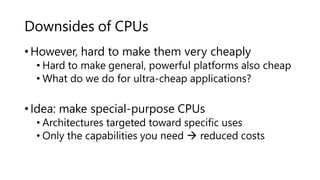
![Electrical power sources
Variable power
supply
2.1mm connector jack
USB to TTL serial cable
9VDC 2.1mm wall
adapter
Plugging in to the Grid
Hand crank
Motor/Generator
[motion]
Solar cell [light] Solar cell [light]
(thin film)
Antenna/
Rectenna
[radio waves]
Thermoelectric
generator
[heat]
Piezoelectric
generator
[vibration]
Energy Harvesting
Coin cell battery
(with leads)
Coin cell battery
AA battery
USB battery
AA battery holder
9V battery snap
9V battery
9V battery holder
C battery
Batteries](https://image.slidesharecdn.com/iot-230725070409-96073381/85/iot-pptx-19-320.jpg)


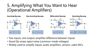


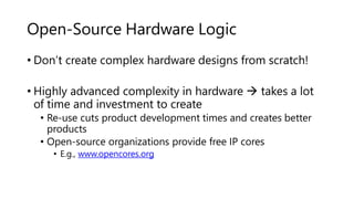
![Manchester (IEEE 802.3):
Up transition for 1, down transition for
0 (further increases transition density,
but requires faster clock)
V+
0V
NRZI [Non-Return to Zero Inverted]:
Transition for 1, no transition for 0. NRZI
is a “differential encoding,
” as value
depends on preceding bits (increases
transition density)
V+
0V
Another Idea: Force There to Be More
Transitions
• Use transitions rather than voltage levels to encode data
• Cause more cycles improve clock synchronization
• Transitions are also easier to detect than levels
NRZ [Non-Return to Zero]:
High voltage for 1, low voltage for 0
(what we’ve been seeing)
V+
0V
0 1 0 0 1 0 1 1 0 0 0 0 1](https://image.slidesharecdn.com/iot-230725070409-96073381/85/iot-pptx-76-320.jpg)


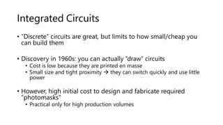
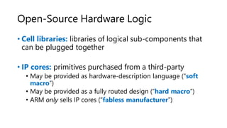
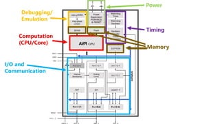
![Memory
Instruction memory
Instruction Register
Memory Address Register
Memory Data Register
Accumulator
Program Counter
0101 0101
Decode
Unit
Arithmetic/Logic
Unit Data memory
Address Value
0111 0000 0011
1000 0001 0110
1001 0011 0111
Opcode [Operand] Instruction
0001 [address] add
0010 [address] subtract
0011 [address] store
0101 [address] load
CPU
Address Bus
Data Bus
Control Bus
Address Value
0000 0101 0111
0001 0001 0110
0010 0011 0111
Status
Fetch
Decode
Execute
000
0
Control
Unit
000
0
“memory
read”
000
1
0101 0111
0101 0111
0111
0000 0011
0000 0011
0000 0011](https://image.slidesharecdn.com/iot-230725070409-96073381/85/iot-pptx-87-320.jpg)


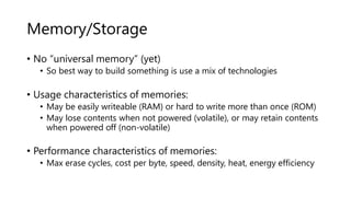


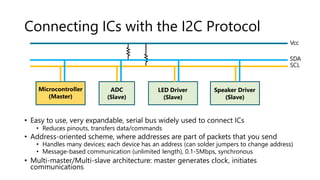
![Serial Programming, Analog I/O
• Analog I/O functions:
• <int>=analogRead(<pin>)
reads voltage from specified
input pin as value between
[0,1023]
• analogWrite(<level>) – sends
voltage level (PWM) to pin,
specified as range from 0
(always off) to 255 (always on)
• analogReference() – sets what
1023 corresponds to for analog
input – DEFAULT (5V),
INTERNAL (1.1V), EXTERNAL
(voltage applied to AREF pin),
etc.](https://image.slidesharecdn.com/iot-230725070409-96073381/85/iot-pptx-130-320.jpg)

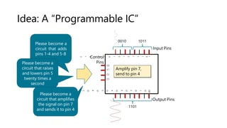
![Digital Streaming I/O Functions
Diagram Function name(s) What it does Notes
Frequency
tone(pin, frequency,
[duration])
Example:
tone(8,500)
Generates a square wave of the
specified frequency in Hz (with
50% duty cycle). Can connect to
piezo buzzer or speaker to play
tones.
Also see: noTone(pin) – stops
generation of square wave on
specified pin.
Times
from here
To
here
pulseIn(pin, value, [timeout])
Example:
unsigned long duration =
pulseIn(3,HIGH)
Measures duration of next received
pulse. E.g. If value is HIGH,
pulseIn() waits for pin to transition
LOWHIGH, starts timer, and ends
on transition HIGHLOW.
Returns 0 if no complete pulse was
received before timeout. Works on
pulses from 10µs → 3 minutes.
Data
byte incoming =
shiftIn(dataPin, clockPin,
bitOrder)
Example:
byte value =
shiftIn(6,7,MSBFIRST)
Shifts a byte of data in from data
pin, with values read on rising
edges of clock pin.
Also see: shiftOut(dataPin,
clockPin, bitOrder, value) – shifts
out the byte value, driving both
data and clock pins appropriately.
Clock
Read Read Read
• Functions for shifting data in/out:](https://image.slidesharecdn.com/iot-230725070409-96073381/85/iot-pptx-132-320.jpg)