Downloaded 2,985 times
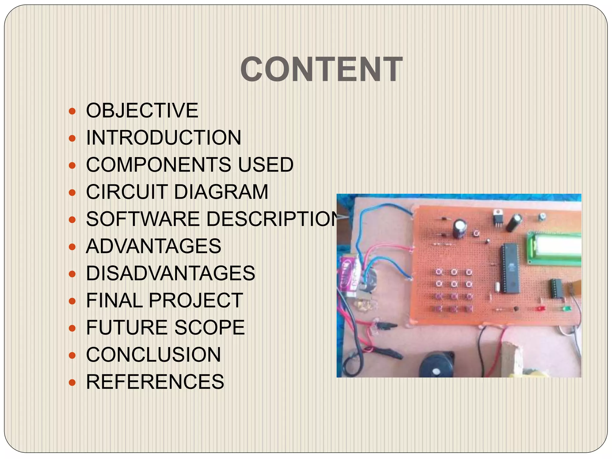
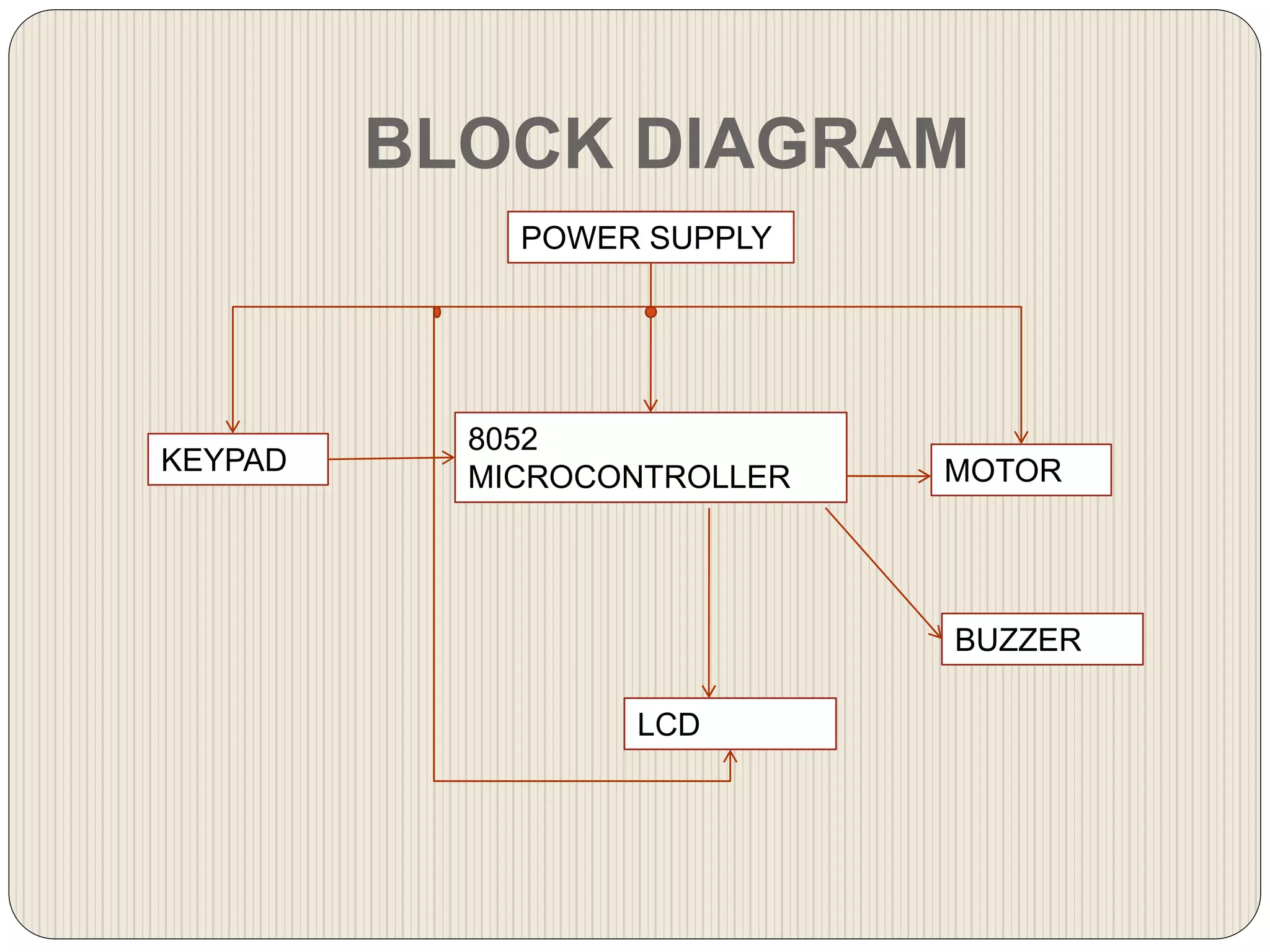
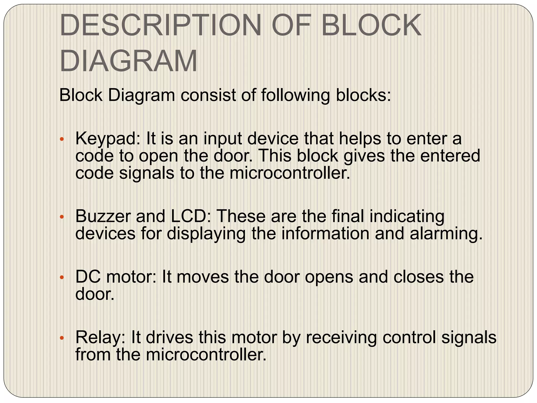
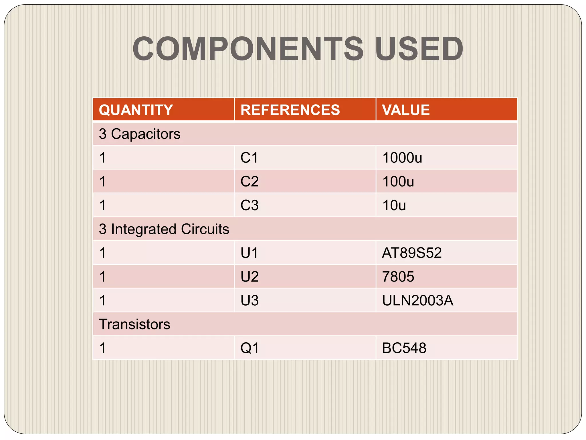
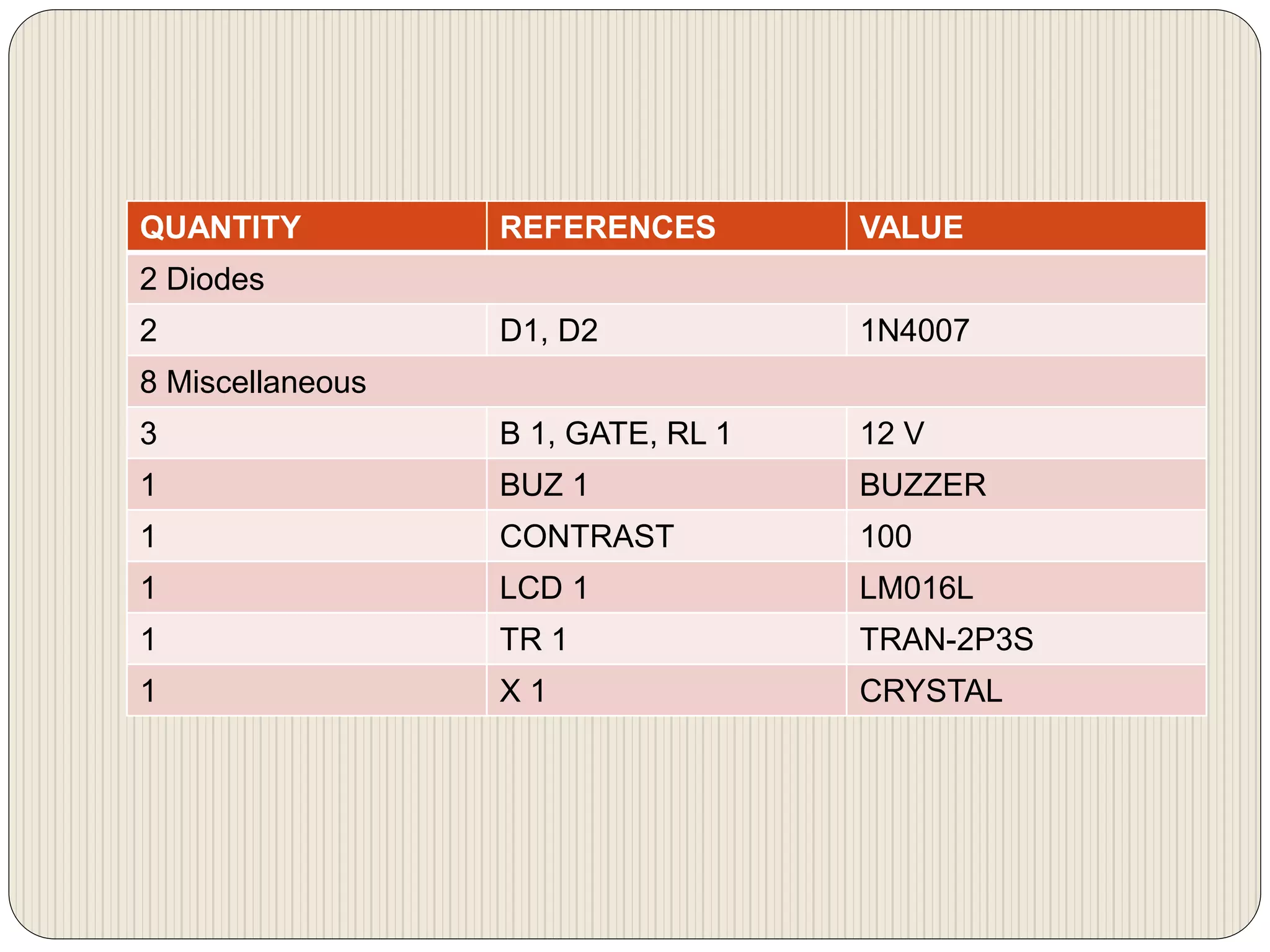
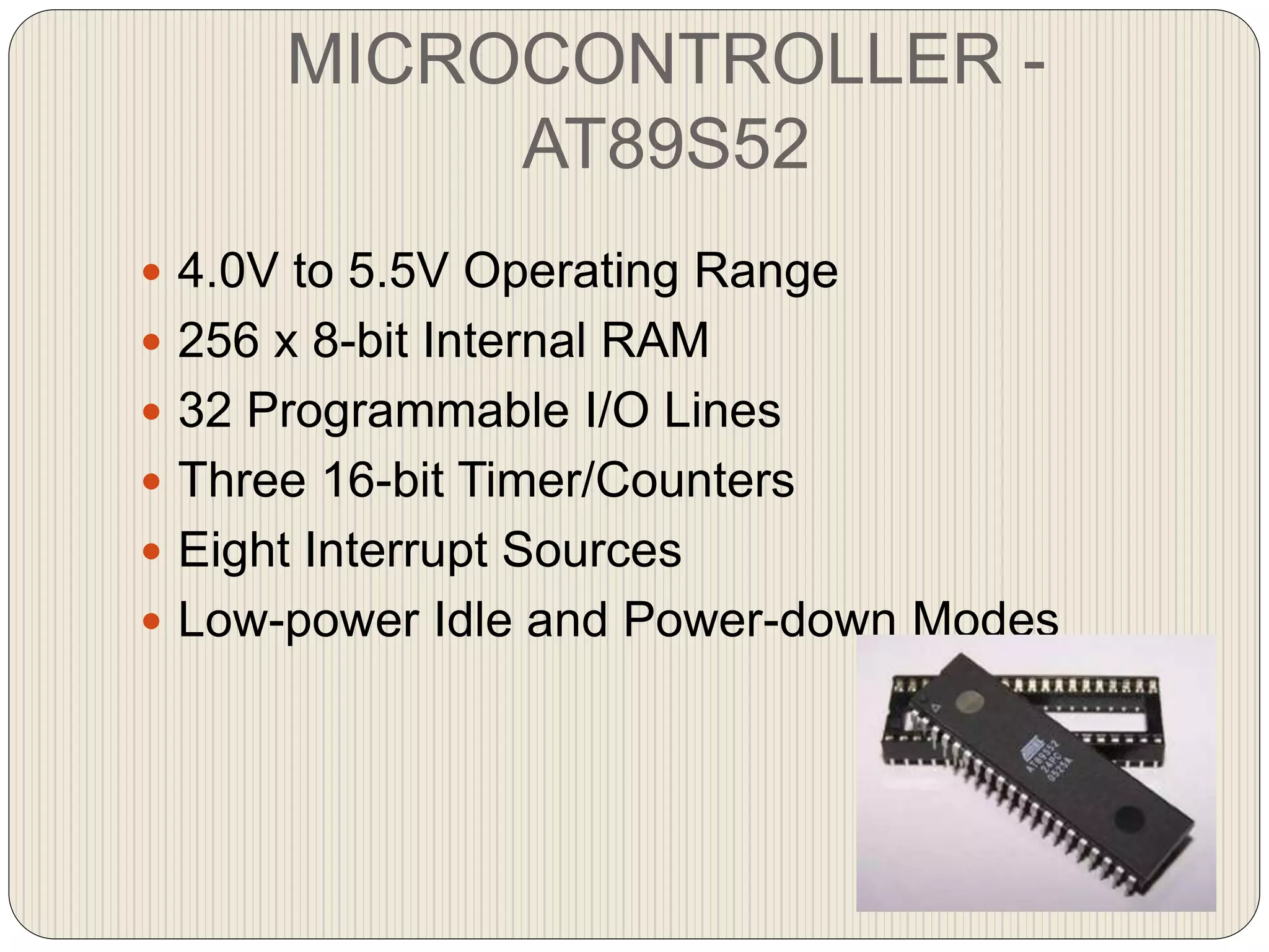
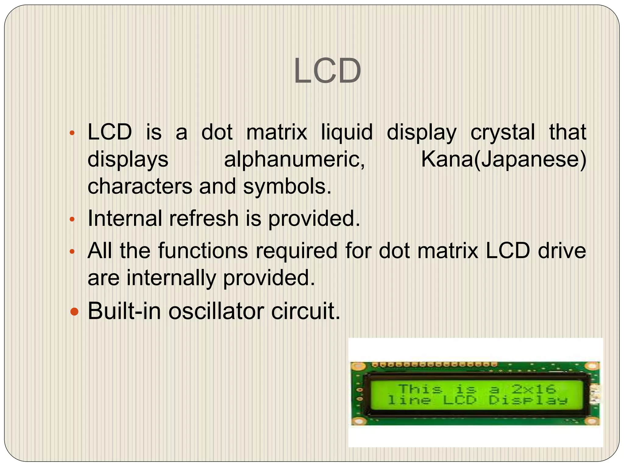
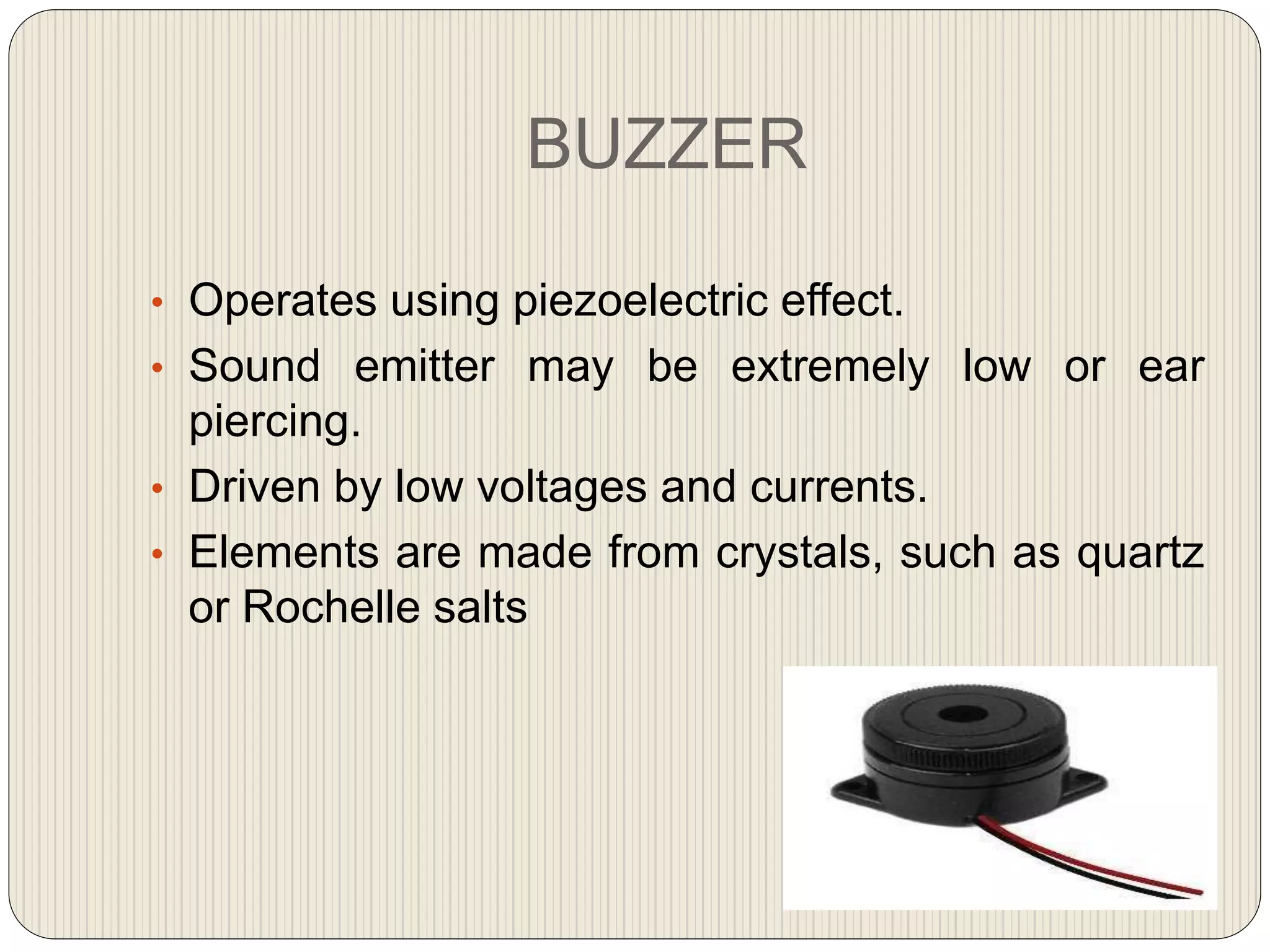
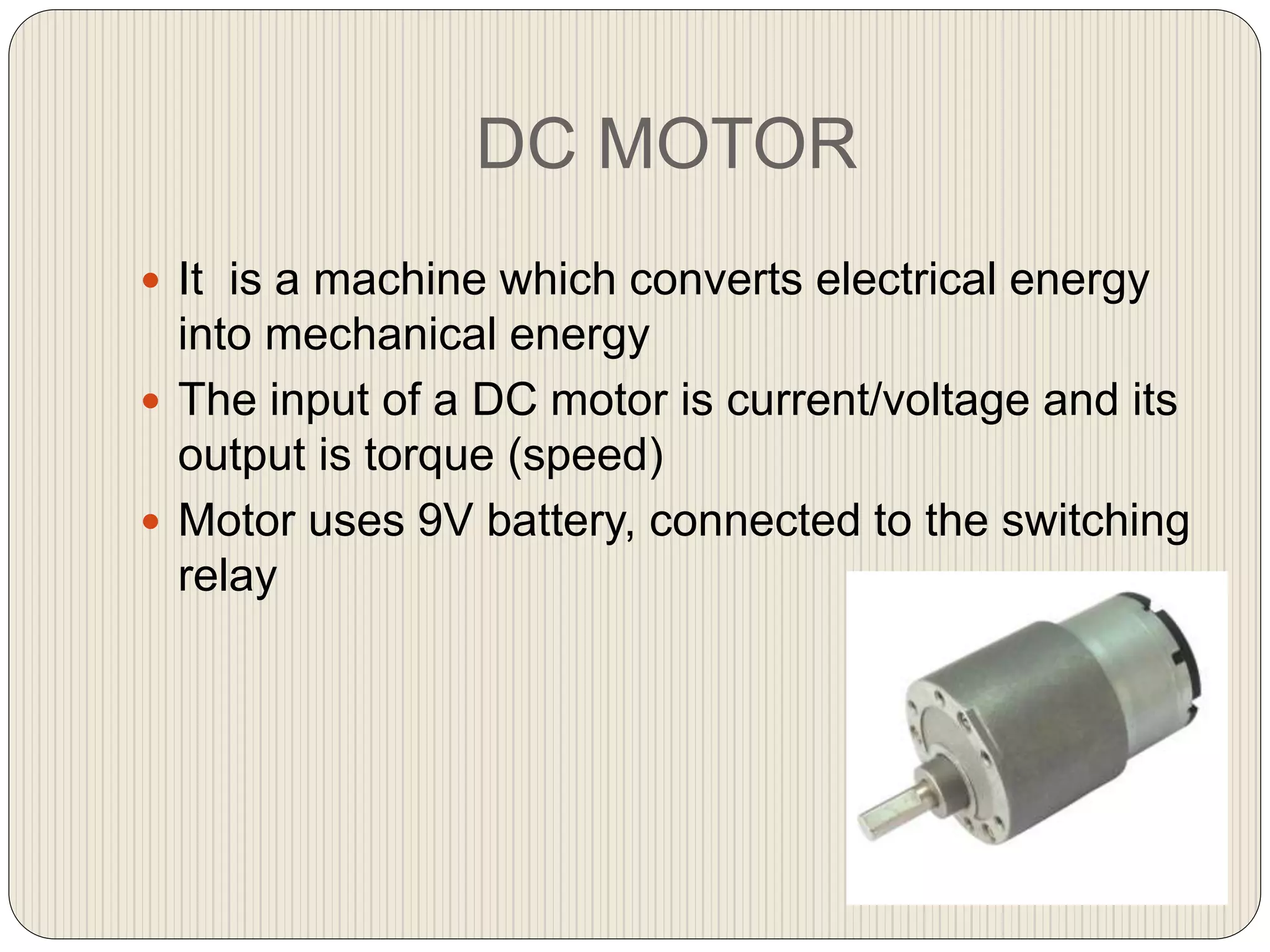
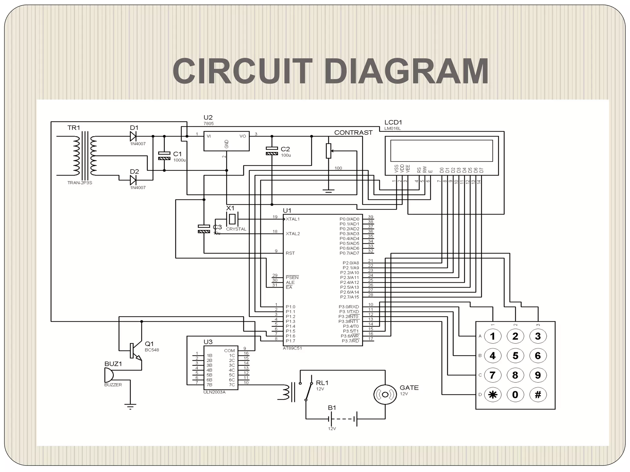
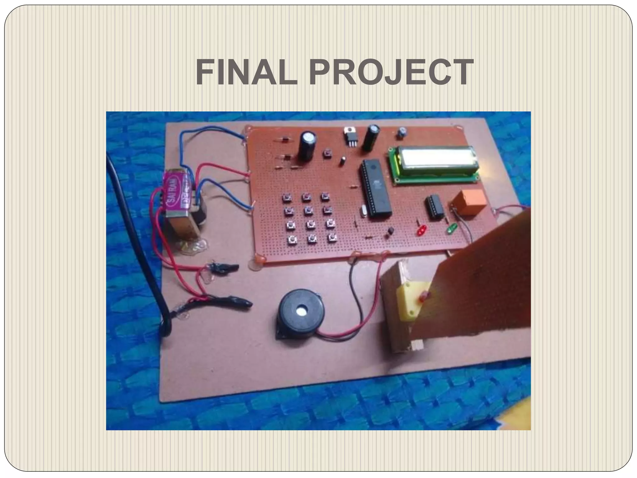
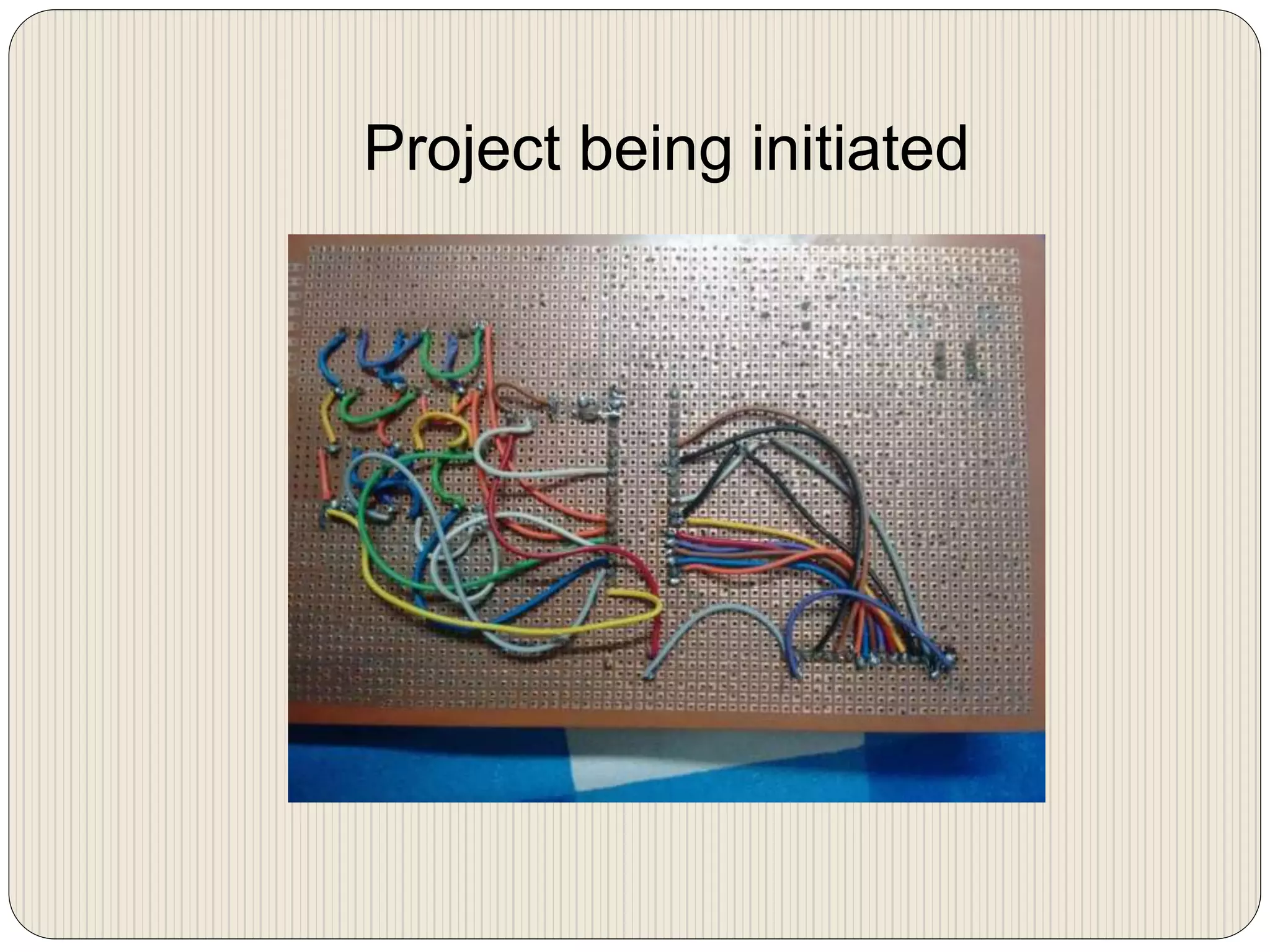
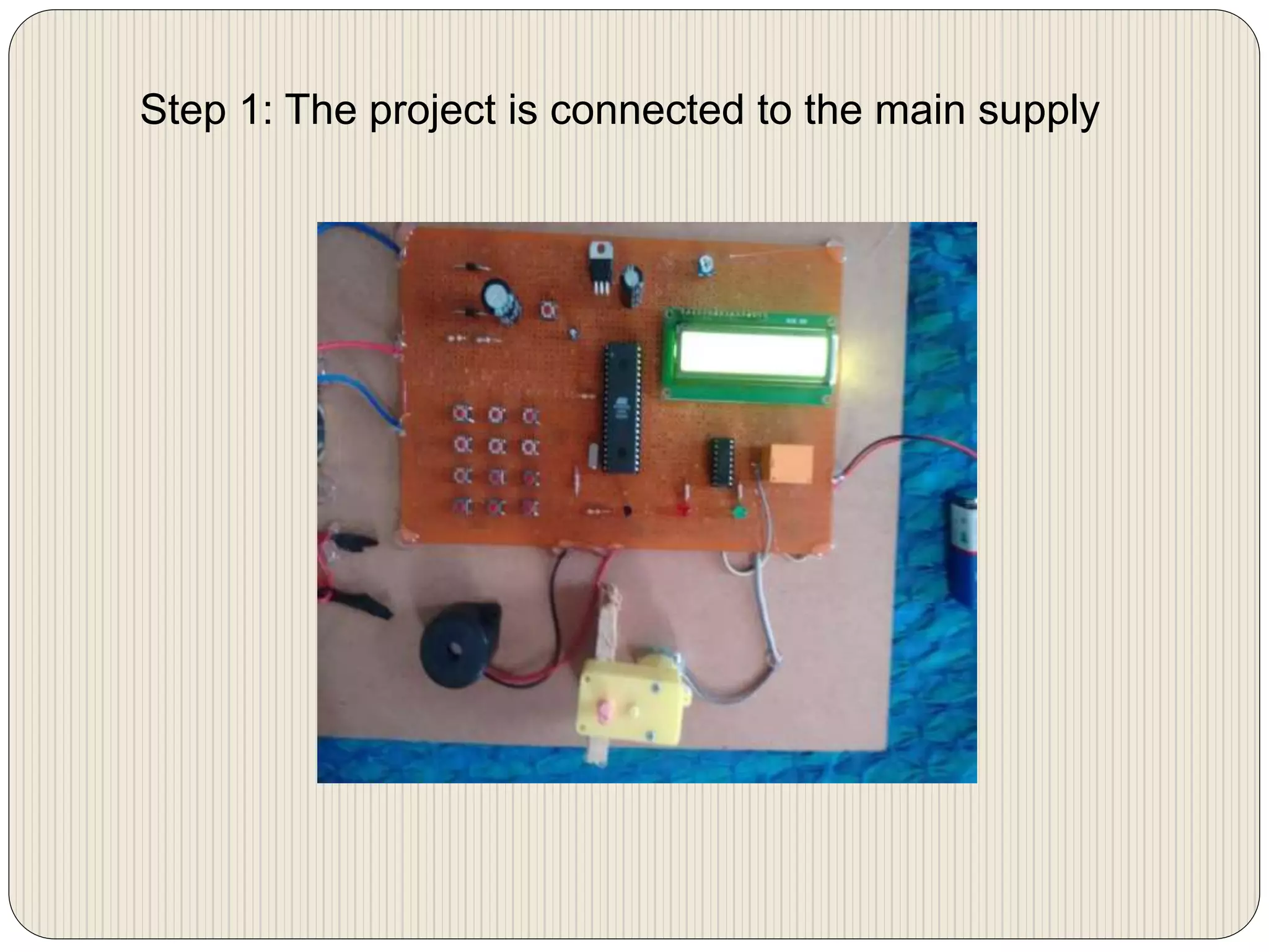
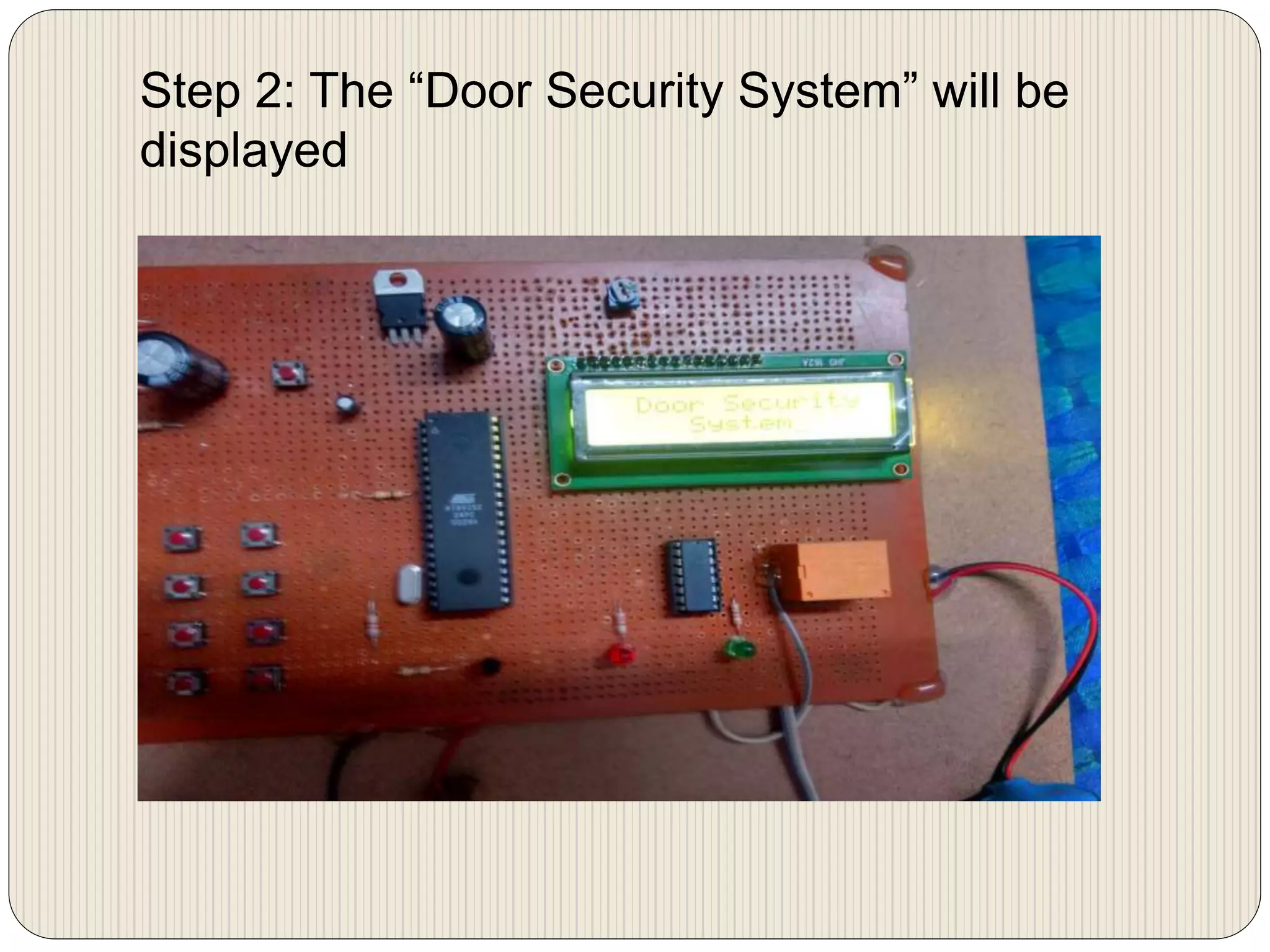
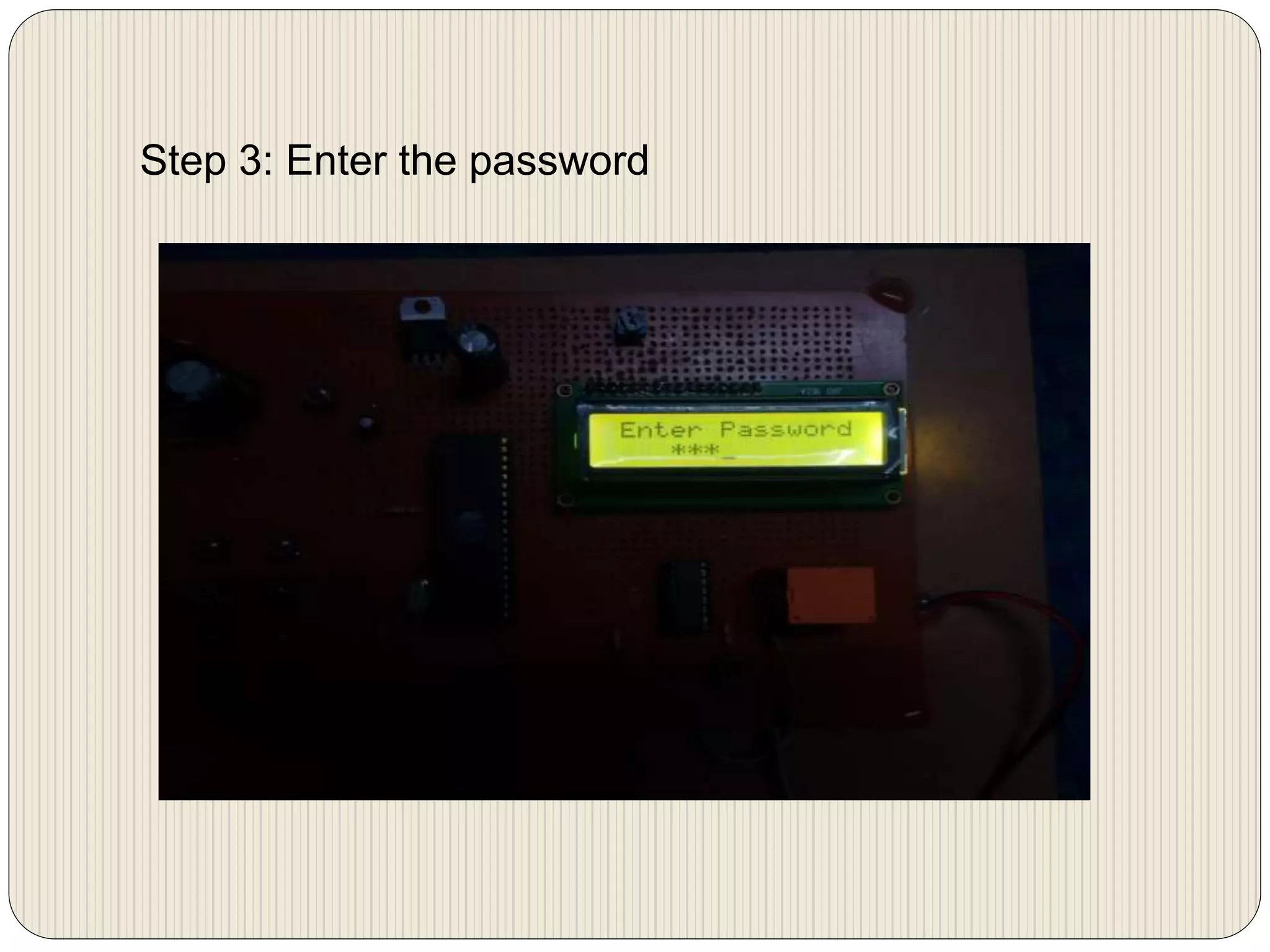


This document describes a password based door locking security system presented by four students. The system uses a microcontroller, keypad, LCD display, buzzer, DC motor, and other components. It allows a user to enter a password to open the door for security and can be used to secure doors, lockers, and other areas. The system was tested and provides advantages like automatic door opening and indication of unauthorized entry while being cost efficient.