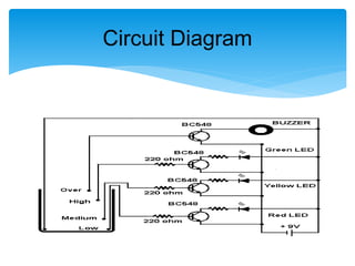
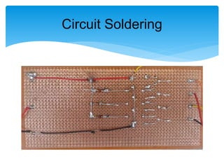
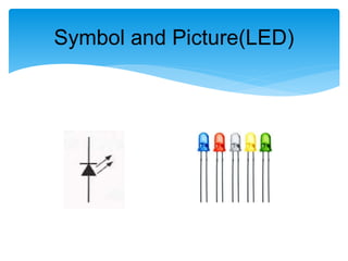
Project
Water Level Indicator
Presented By:
AbdulRehman (BSSE09151014)
The University of Lahore, Gujrat Campus
Circuit Diagram
 Introduction
 Working Principle
 Soldering
 LED
 Resistance
 Transistor(BC548)
 Electric Buzzer
 Printed Circuit Board(PCB)
 Scope
Components
 This circuit not only indicates the amount of water present in the
overhead tank but also gives an alarm when the tank is full.
 When the water is empty the wires in the tank are open circuited
and the 220K resistors pulls the switch low hence opening
the switch and LEDs are OFF.
 As the water starts filling up, first the wire in the tank connected
to Low indication wire and the +supply are shorted by water.
 This closes the switch Low indication wire and turns the LED1
ON. As the water continues to fill the tank, the LEDs2 and 3
lights up gradually.
 When the water is full, the base of the transistor BC548 is pulled
high by the water and this saturates the transistor, turning the
buzzer ON
Introduction
 One electrode wire is with 9V Battery is placed at
the bottom of tank. Next wires are placed step by
step above the bottom probe. When the water
comes in contact with the electrode tip, a
conductive path is established between the
sense electrode and the tank wall/reference
electrode, which in turn makes the transistors
conduct to glow LED and indicate the level of
water.
Working Principle
 Soldering is a process in which two or more metal
items are joined together by melting and flowing a
filler metal into the joint, the filler metal having a
relatively low melting point.
 After the metal cools, the resulting joints are not as
strong as the base metal, but have adequate
strength, electrical conductivity, and water-
tightness for many uses.
Soldering
Circuit Soldering
 A light-emitting diode (LED) is an electronic light
source. LEDs are used as indicator lamps in many
kinds of electronics and increasingly for lighting.
LEDs work by the effect of electroluminescence. .
When the diode is forward biased (switched on),
electrons are able to recombine with holes and
energy is released in the form of light. This effect is
called electroluminescence
LED
Symbol and Picture(LED)
The electrical resistance of an object is a measure of its
opposition to the passage of a steady current. It is
discovered by George Ohm in the late of 1820s. The SI
unit of the electrical resistance is the Ohm (Ω). . The
resistance of a resistive object determines the amount of
current through the object for a given potential difference
V across the object, in accordance with Ohm’s law;
𝐼 =
𝑉
𝑅
Where R is the resistance of the object, measure in
ohms, equivalent to 𝑱.
𝒔
𝑪 𝟐
Resistance
Symbol and Picture(Resistance)
 A transistor is a semiconductor device commonly
uses to amplify or switch electronic signals.
 A transistor is made of a solid piece of
semiconductor material, with at least three
terminals for connection to an external circuit.
 This is a NPN Transistor.
Transistor(BC548)
Electric Buzzer
 A piezoelectric buzzer consists of an electric
ceramic plate which has electrodes on both sides
and a metal plate
 An electric ceramic plate is attached to a metal to a
metal plate with adhesives.
 . Applying D.C voltage between electrodes of a
piezoelectric ceramic plate causes mechanical
distortion due to piezoelectric effect.
 A printed circuit board, or PCB, is used to
mechanically support and electrically connect
electronic components using conductive path
ways, tracks, or traces, etched from copper sheets
laminated on to a non-conductive substrate
Printed Circuit Board(PCB)
 Now no need to go on the roof to look the water
level.
 It shows the water level in your room like 1/4 tank,
1/2 tank, 3/4 tank and full tank.
 Alarm starts ringing as soon as tank becomes full.
 Suitable for every tank.
Scope
Any Question???

Water Level Indicator Project Presentation

  • 1.
    Project Water Level Indicator PresentedBy: AbdulRehman (BSSE09151014) The University of Lahore, Gujrat Campus
  • 2.
  • 3.
     Introduction  WorkingPrinciple  Soldering  LED  Resistance  Transistor(BC548)  Electric Buzzer  Printed Circuit Board(PCB)  Scope Components
  • 4.
     This circuitnot only indicates the amount of water present in the overhead tank but also gives an alarm when the tank is full.  When the water is empty the wires in the tank are open circuited and the 220K resistors pulls the switch low hence opening the switch and LEDs are OFF.  As the water starts filling up, first the wire in the tank connected to Low indication wire and the +supply are shorted by water.  This closes the switch Low indication wire and turns the LED1 ON. As the water continues to fill the tank, the LEDs2 and 3 lights up gradually.  When the water is full, the base of the transistor BC548 is pulled high by the water and this saturates the transistor, turning the buzzer ON Introduction
  • 5.
     One electrodewire is with 9V Battery is placed at the bottom of tank. Next wires are placed step by step above the bottom probe. When the water comes in contact with the electrode tip, a conductive path is established between the sense electrode and the tank wall/reference electrode, which in turn makes the transistors conduct to glow LED and indicate the level of water. Working Principle
  • 6.
     Soldering isa process in which two or more metal items are joined together by melting and flowing a filler metal into the joint, the filler metal having a relatively low melting point.  After the metal cools, the resulting joints are not as strong as the base metal, but have adequate strength, electrical conductivity, and water- tightness for many uses. Soldering
  • 7.
  • 8.
     A light-emittingdiode (LED) is an electronic light source. LEDs are used as indicator lamps in many kinds of electronics and increasingly for lighting. LEDs work by the effect of electroluminescence. . When the diode is forward biased (switched on), electrons are able to recombine with holes and energy is released in the form of light. This effect is called electroluminescence LED
  • 9.
  • 10.
    The electrical resistanceof an object is a measure of its opposition to the passage of a steady current. It is discovered by George Ohm in the late of 1820s. The SI unit of the electrical resistance is the Ohm (Ω). . The resistance of a resistive object determines the amount of current through the object for a given potential difference V across the object, in accordance with Ohm’s law; 𝐼 = 𝑉 𝑅 Where R is the resistance of the object, measure in ohms, equivalent to 𝑱. 𝒔 𝑪 𝟐 Resistance
  • 11.
  • 12.
     A transistoris a semiconductor device commonly uses to amplify or switch electronic signals.  A transistor is made of a solid piece of semiconductor material, with at least three terminals for connection to an external circuit.  This is a NPN Transistor. Transistor(BC548)
  • 13.
    Electric Buzzer  Apiezoelectric buzzer consists of an electric ceramic plate which has electrodes on both sides and a metal plate  An electric ceramic plate is attached to a metal to a metal plate with adhesives.  . Applying D.C voltage between electrodes of a piezoelectric ceramic plate causes mechanical distortion due to piezoelectric effect.
  • 14.
     A printedcircuit board, or PCB, is used to mechanically support and electrically connect electronic components using conductive path ways, tracks, or traces, etched from copper sheets laminated on to a non-conductive substrate Printed Circuit Board(PCB)
  • 15.
     Now noneed to go on the roof to look the water level.  It shows the water level in your room like 1/4 tank, 1/2 tank, 3/4 tank and full tank.  Alarm starts ringing as soon as tank becomes full.  Suitable for every tank. Scope
  • 16.