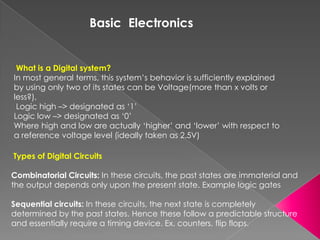
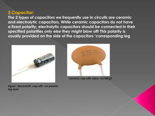
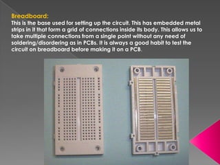
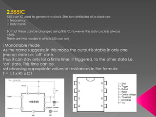
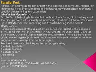
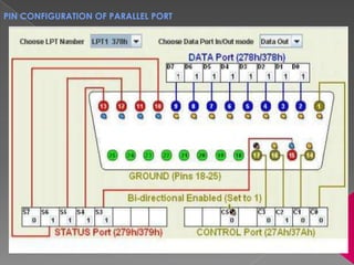
SUBMITTED TO:-   SUBMITTED BY:-
MRS. NIDHI MAM     GOPAL DHAKER
TRAINING AT :-

         CLUB FIRST
TECHNO EDUSOLUTIONS PVT. LTD.

             ON

EMBEDDED SYSTEM & ROBOTICS
ABOUT COMPANY PROFILE
              Club First is a group of students and some technical
             experts who put in their ideas for improvement and research
             in science& technology. Club First is now in several technical
             institutes allover the nation, with about 8500 members, thus
             rated as India's biggest technical club. Club first is registered
             as name "CLUB FIRST TECHNO EDUSOLUTIONS PVT. LTD. INDIA”
             by ministry of corporations affairs of India .


              CLUB FIRST is now at every technical corner, not only in
             around the Maharashtra but also in the city Jaipur, Alwar,
             Ahmadabad, Kolkata, Thus become India‟s biggest
             Technical Platform


Club first
Introduction to Embedded system

 Definition:
 An Embedded System is one that has
 computer hardware with software embedded in it as
 one of its important components. Or in other words we
 can say an embedded system is the system which is
 designed to perform a specific task only.


 Three basic part of embedded system:-
  Basic Electronic & Component.
 Important Integrated Circuits and
 Implementation.
 Microcontroller & parallel port.
Basic Electronics


 What is a Digital system?
In most general terms, this system‟s behavior is sufficiently explained
by using only two of its states can be Voltage(more than x volts or
less?),
 Logic high –> designated as „1‟
Logic low –> designated as „0‟
Where high and low are actually „higher‟ and „lower‟ with respect to
a reference voltage level (ideally taken as 2.5V)

Types of Digital Circuits

Combinatorial Circuits: In these circuits, the past states are immaterial and
the output depends only upon the present state. Example logic gates

Sequential circuits: In these circuits, the next state is completely
determined by the past states. Hence these follow a predictable structure
and essentially require a timing device. Ex. counters, flip flops.
Clock: Building block of a sequential circuit
A clock is simply alternate high and low states of voltage with time i.e. essentially
a square wave. Important terms related to clock are its duty cycle and its
frequency:
Duty cycle: It is the ratio of Th and Th+Tl
                                            = ℎ/ + ℎ


Logic Gates: Building block of a combinatorial circuitry
These are essentially combinatorial circuits used to implement logical Boolean
operations like AND, NAND, OR, XOR and NOT. NOT and NAND are called
universal gates as any other gate can be formed using either of them!
Practical Circuiting Elements

1.Resistor:
Resistors offer a resistance to the flow of current. Mainly resistors are
classified according to their resistance
values and their power ratings. Resistances range from 10 ohm to
56Mohm (or more) and owner ratings
from 1/8W to 20W.


              The 1st two bands specify the 2 digits of the resistor value
               whereas the 3rd band specifies the multiplier in terms of the
               power to which 10 is raised and multiplied to the 2 digits.
              The tolerance tells the possible % variation of the resistor
               value about the value indicated by bands.
2.Capacitor:
The 2 types of capacitors we frequently use in circuits are ceramic
and electrolytic capacitors. While ceramic capacitors do not have
a fixed polarity; electrolytic capacitors should be connected in their
specified polarities only else they might blow off! This polarity is
usually provided on the side of the capacitors ‘corresponding leg


                                              Ceramic cap with value 15x104 pF

Figure : Electrolytic cap with –ve polarity
leg seen
Breadboard:
This is the base used for setting up the circuit. This has embedded metal
strips in it that form a grid of connections inside its body. This allows us to
take multiple connections from a single point without any need of
soldering/disordering as in PCBs. It is always a good habit to test the
circuit on breadboard before making it on a PCB.
3.LED
LED (Light Emitting Diode) is frequently used to display the outputs at various
 stages of the circuit. It is essentially a Diode with the energy released in the
 form of photons due to electron transitions falling in the visible region.
Hence normal diode properties apply to it. It glows only in fwd bias mode
i.e. with p junction connected to +ve voltage and n junction to negative.
Diodes are essentially low power devices. The current through the LED should
be less than 20mA.Hence always put a 220 ohm resistor in series with the LED.
Never forget that LEDs consume a significant amount of power of the outputs
of the ICs (CMOS based).Hence it is advisable to only use them for checking
the voltage level (high or low) and then remove them.
Some important Integrated Circuits and
                   Implementation

1.Power supply
Embedded system always uses +5 volt regulated power supply. For this we
use 7805 voltage regulator
IC.
adapter‟s supply to generate +5V here. Connect the gnd and +12V of
adapter to the pins as shown
and get +5V directly as an output out of the 3rd pin. Current up to 0.5 A can
be obtained from this
regulator without any significant fall in voltage level.
2.555IC
  555 is an IC used to generate a clock .The two attributes of a clock are
  Frequency
  Duty cycle.

  Both of these can be changed using this IC, however the duty cycle is always
  <50%.
  There are two modes in which 555 can run

i Monostable mode
As the name suggests; in this mode the output is stable in only one
(mono) state i.e. „off‟ state.
Thus it can stay only for a finite time, if triggered, to the other state i.e.
„on‟ state. This time can be
set choosing appropriate values of resistances in the formula:
T = 1.1 x R1 x C1
II Astable mode

In this mode; the output is stable neither in „high‟ state nor in „low ‟ state.
Hence it oscillates from one state to another giving us a square wave or
clock. We can set the clock frequency and Duty cycle D by the formulae:
F= . / +                D = ( + )/( +          )
3. RF Transmitter RF receiver (HT12D &HT12E ICs)
Transmitter:
At the transmitter side we use HT12E encoder IC. Here we have the pin diagram
and data sequence of
the IC.
 Receiver:
 At the Receiver side we use HT12D encoder IC. Here we have the pin diagram
 and data sequence of the IC
4.MOTOR DRIVER:
At receiver side we use HT12D Decoder IC, This is the serial in and Parallel out
Configuration. The out pin of the decoder directly connects to the INPUT pin of
the L293D Motor driver IC. T
he L293 and L293D are quadruple high-current half-H drivers. The L293 is designed
to provide
bidirectional drive currents of up to 1 A at voltages from 4.5 V to 36 V. The L293D is
designed to provide
bidirectional drive currents of up to 600-mA at voltages from 4.5 V to 36 V
5.Mobile and telecommunication
For automation through mobile we use Duel tone multiple frequency
decoder
DTMF DECODER:
Introduction to Microcontroller
Microcontroller is a small (micro) single-chip
computer designed to perform a specific function,
and the specific function is to control (controller) objects,
 processes or events.

It is dedicated to one task, or a set of closely related task
. It is similar to a personal computer, it has similar
components built on to a single chip:

        CPU, Memory (ROM and RAM)
        I/O ports, Serial ports
        Timer
Pin Configuration of 8051 microcontroller
Features of 8051
• 4K Bytes of In-System Programmable (ISP) Flash Memory
• 4.0V to 5.5V Operating Range
• Fully Static Operation: 0 Hz to 33 MHz
• Three-level Program Memory Lock
• 128 x 8-bit Internal RAM
• 32 Programmable I/O Lines
• Two 16-bit Timer/Counters
• Six Interrupt Sources
• Full Duplex UART Serial Channel
• Low-power Idle and Power-down Modes
• Interrupt Recovery from Power-down Mode
• Watchdog Timer
• Dual Data Pointer
• Power-off Flag
• Fast Programming Time
• Flexible ISP Programming (Byte and Page Mode)
Parallel Port:
Parallel Port is same as the printer port in the back side of computer. Parallel Port
 Interfacing is the simplest method of interfacing. Now parallel port interfacing is
used for programming microcontrollers
Introduction of parallel port:
Parallel Port interfacing is the simplest method of interfacing. So it is widely used.
The main problem with parallel port interfacing is that it has data transfer speed
up to 1Mbytes/sec. USB interfacing are Available having speed near to
12MBytes/sec.
Parallel port is basically the 25 pin Female connector (DB-25) in the back side
of the computer (PrinterPort). It has 17 input Lines for input port and 12 pins for
output port. Out of the 25 pins most pins areGround and there is data register
(8 bit), control register (4 bit) and status We can input port through all thethree
 registers and can output port only through
See the simple basics for the parallel port programming.
#include<studio.h>
#include<conio.h>
#include<dos.h>
void main ( )
{
const int PORT=0x0378;
outport (PORT,255 ); // TO ENABEL ALL THE DATA
getch (); // PORT HIGH
PIN CONFIGURATION OF PARALLEL PORT
THANKS


 I WANT TO EXPRESS MY SINCERE THANKS TO
 “CLUB FIRST” FOR giving us such a good
 training and for making our future
 bright.Faciliators at CLUB FIRST JAIPUR
 CENTER:

 Bhuvnesh Mishra
 M.D, club first.
embedded system

embedded system

  • 2.
    SUBMITTED TO:- SUBMITTED BY:- MRS. NIDHI MAM GOPAL DHAKER
  • 3.
    TRAINING AT :- CLUB FIRST TECHNO EDUSOLUTIONS PVT. LTD. ON EMBEDDED SYSTEM & ROBOTICS
  • 4.
    ABOUT COMPANY PROFILE  Club First is a group of students and some technical experts who put in their ideas for improvement and research in science& technology. Club First is now in several technical institutes allover the nation, with about 8500 members, thus rated as India's biggest technical club. Club first is registered as name "CLUB FIRST TECHNO EDUSOLUTIONS PVT. LTD. INDIA” by ministry of corporations affairs of India .  CLUB FIRST is now at every technical corner, not only in around the Maharashtra but also in the city Jaipur, Alwar, Ahmadabad, Kolkata, Thus become India‟s biggest Technical Platform Club first
  • 5.
    Introduction to Embeddedsystem Definition: An Embedded System is one that has computer hardware with software embedded in it as one of its important components. Or in other words we can say an embedded system is the system which is designed to perform a specific task only. Three basic part of embedded system:-  Basic Electronic & Component. Important Integrated Circuits and Implementation. Microcontroller & parallel port.
  • 6.
    Basic Electronics Whatis a Digital system? In most general terms, this system‟s behavior is sufficiently explained by using only two of its states can be Voltage(more than x volts or less?), Logic high –> designated as „1‟ Logic low –> designated as „0‟ Where high and low are actually „higher‟ and „lower‟ with respect to a reference voltage level (ideally taken as 2.5V) Types of Digital Circuits Combinatorial Circuits: In these circuits, the past states are immaterial and the output depends only upon the present state. Example logic gates Sequential circuits: In these circuits, the next state is completely determined by the past states. Hence these follow a predictable structure and essentially require a timing device. Ex. counters, flip flops.
  • 7.
    Clock: Building blockof a sequential circuit A clock is simply alternate high and low states of voltage with time i.e. essentially a square wave. Important terms related to clock are its duty cycle and its frequency: Duty cycle: It is the ratio of Th and Th+Tl = ℎ/ + ℎ Logic Gates: Building block of a combinatorial circuitry These are essentially combinatorial circuits used to implement logical Boolean operations like AND, NAND, OR, XOR and NOT. NOT and NAND are called universal gates as any other gate can be formed using either of them!
  • 8.
    Practical Circuiting Elements 1.Resistor: Resistorsoffer a resistance to the flow of current. Mainly resistors are classified according to their resistance values and their power ratings. Resistances range from 10 ohm to 56Mohm (or more) and owner ratings from 1/8W to 20W. The 1st two bands specify the 2 digits of the resistor value whereas the 3rd band specifies the multiplier in terms of the power to which 10 is raised and multiplied to the 2 digits. The tolerance tells the possible % variation of the resistor value about the value indicated by bands.
  • 9.
    2.Capacitor: The 2 typesof capacitors we frequently use in circuits are ceramic and electrolytic capacitors. While ceramic capacitors do not have a fixed polarity; electrolytic capacitors should be connected in their specified polarities only else they might blow off! This polarity is usually provided on the side of the capacitors ‘corresponding leg Ceramic cap with value 15x104 pF Figure : Electrolytic cap with –ve polarity leg seen
  • 10.
    Breadboard: This is thebase used for setting up the circuit. This has embedded metal strips in it that form a grid of connections inside its body. This allows us to take multiple connections from a single point without any need of soldering/disordering as in PCBs. It is always a good habit to test the circuit on breadboard before making it on a PCB.
  • 11.
    3.LED LED (Light EmittingDiode) is frequently used to display the outputs at various stages of the circuit. It is essentially a Diode with the energy released in the form of photons due to electron transitions falling in the visible region. Hence normal diode properties apply to it. It glows only in fwd bias mode i.e. with p junction connected to +ve voltage and n junction to negative. Diodes are essentially low power devices. The current through the LED should be less than 20mA.Hence always put a 220 ohm resistor in series with the LED. Never forget that LEDs consume a significant amount of power of the outputs of the ICs (CMOS based).Hence it is advisable to only use them for checking the voltage level (high or low) and then remove them.
  • 12.
    Some important IntegratedCircuits and Implementation 1.Power supply Embedded system always uses +5 volt regulated power supply. For this we use 7805 voltage regulator IC. adapter‟s supply to generate +5V here. Connect the gnd and +12V of adapter to the pins as shown and get +5V directly as an output out of the 3rd pin. Current up to 0.5 A can be obtained from this regulator without any significant fall in voltage level.
  • 13.
    2.555IC 555is an IC used to generate a clock .The two attributes of a clock are Frequency Duty cycle. Both of these can be changed using this IC, however the duty cycle is always <50%. There are two modes in which 555 can run i Monostable mode As the name suggests; in this mode the output is stable in only one (mono) state i.e. „off‟ state. Thus it can stay only for a finite time, if triggered, to the other state i.e. „on‟ state. This time can be set choosing appropriate values of resistances in the formula: T = 1.1 x R1 x C1
  • 14.
    II Astable mode Inthis mode; the output is stable neither in „high‟ state nor in „low ‟ state. Hence it oscillates from one state to another giving us a square wave or clock. We can set the clock frequency and Duty cycle D by the formulae: F= . / + D = ( + )/( + )
  • 15.
    3. RF TransmitterRF receiver (HT12D &HT12E ICs) Transmitter: At the transmitter side we use HT12E encoder IC. Here we have the pin diagram and data sequence of the IC. Receiver: At the Receiver side we use HT12D encoder IC. Here we have the pin diagram and data sequence of the IC
  • 16.
    4.MOTOR DRIVER: At receiverside we use HT12D Decoder IC, This is the serial in and Parallel out Configuration. The out pin of the decoder directly connects to the INPUT pin of the L293D Motor driver IC. T he L293 and L293D are quadruple high-current half-H drivers. The L293 is designed to provide bidirectional drive currents of up to 1 A at voltages from 4.5 V to 36 V. The L293D is designed to provide bidirectional drive currents of up to 600-mA at voltages from 4.5 V to 36 V
  • 17.
    5.Mobile and telecommunication Forautomation through mobile we use Duel tone multiple frequency decoder DTMF DECODER:
  • 18.
    Introduction to Microcontroller Microcontrolleris a small (micro) single-chip computer designed to perform a specific function, and the specific function is to control (controller) objects, processes or events. It is dedicated to one task, or a set of closely related task . It is similar to a personal computer, it has similar components built on to a single chip: CPU, Memory (ROM and RAM) I/O ports, Serial ports Timer
  • 19.
    Pin Configuration of8051 microcontroller
  • 20.
    Features of 8051 •4K Bytes of In-System Programmable (ISP) Flash Memory • 4.0V to 5.5V Operating Range • Fully Static Operation: 0 Hz to 33 MHz • Three-level Program Memory Lock • 128 x 8-bit Internal RAM • 32 Programmable I/O Lines • Two 16-bit Timer/Counters • Six Interrupt Sources • Full Duplex UART Serial Channel • Low-power Idle and Power-down Modes • Interrupt Recovery from Power-down Mode • Watchdog Timer • Dual Data Pointer • Power-off Flag • Fast Programming Time • Flexible ISP Programming (Byte and Page Mode)
  • 22.
    Parallel Port: Parallel Portis same as the printer port in the back side of computer. Parallel Port Interfacing is the simplest method of interfacing. Now parallel port interfacing is used for programming microcontrollers Introduction of parallel port: Parallel Port interfacing is the simplest method of interfacing. So it is widely used. The main problem with parallel port interfacing is that it has data transfer speed up to 1Mbytes/sec. USB interfacing are Available having speed near to 12MBytes/sec. Parallel port is basically the 25 pin Female connector (DB-25) in the back side of the computer (PrinterPort). It has 17 input Lines for input port and 12 pins for output port. Out of the 25 pins most pins areGround and there is data register (8 bit), control register (4 bit) and status We can input port through all thethree registers and can output port only through See the simple basics for the parallel port programming. #include<studio.h> #include<conio.h> #include<dos.h> void main ( ) { const int PORT=0x0378; outport (PORT,255 ); // TO ENABEL ALL THE DATA getch (); // PORT HIGH
  • 23.
    PIN CONFIGURATION OFPARALLEL PORT
  • 24.
    THANKS I WANTTO EXPRESS MY SINCERE THANKS TO “CLUB FIRST” FOR giving us such a good training and for making our future bright.Faciliators at CLUB FIRST JAIPUR CENTER: Bhuvnesh Mishra M.D, club first.