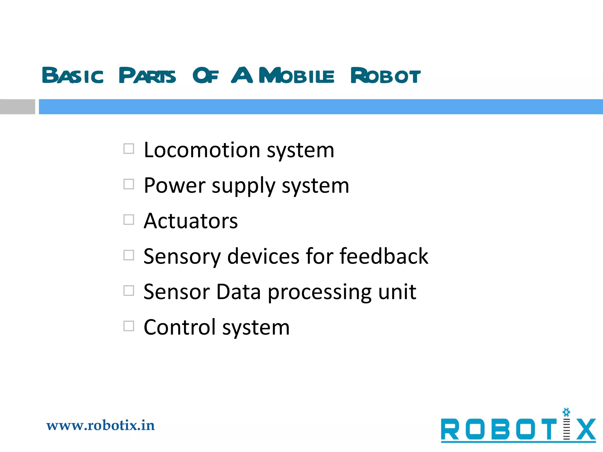
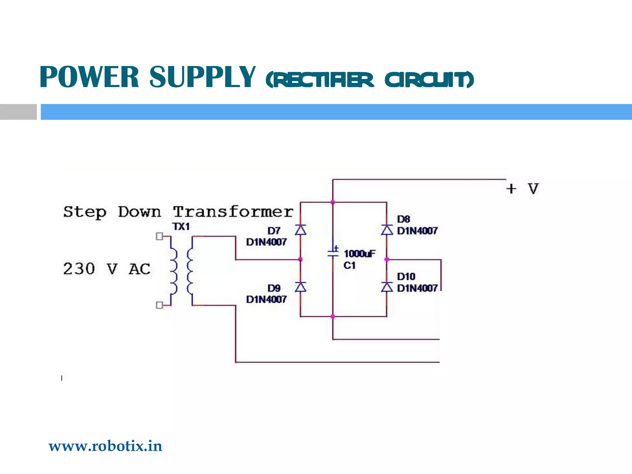
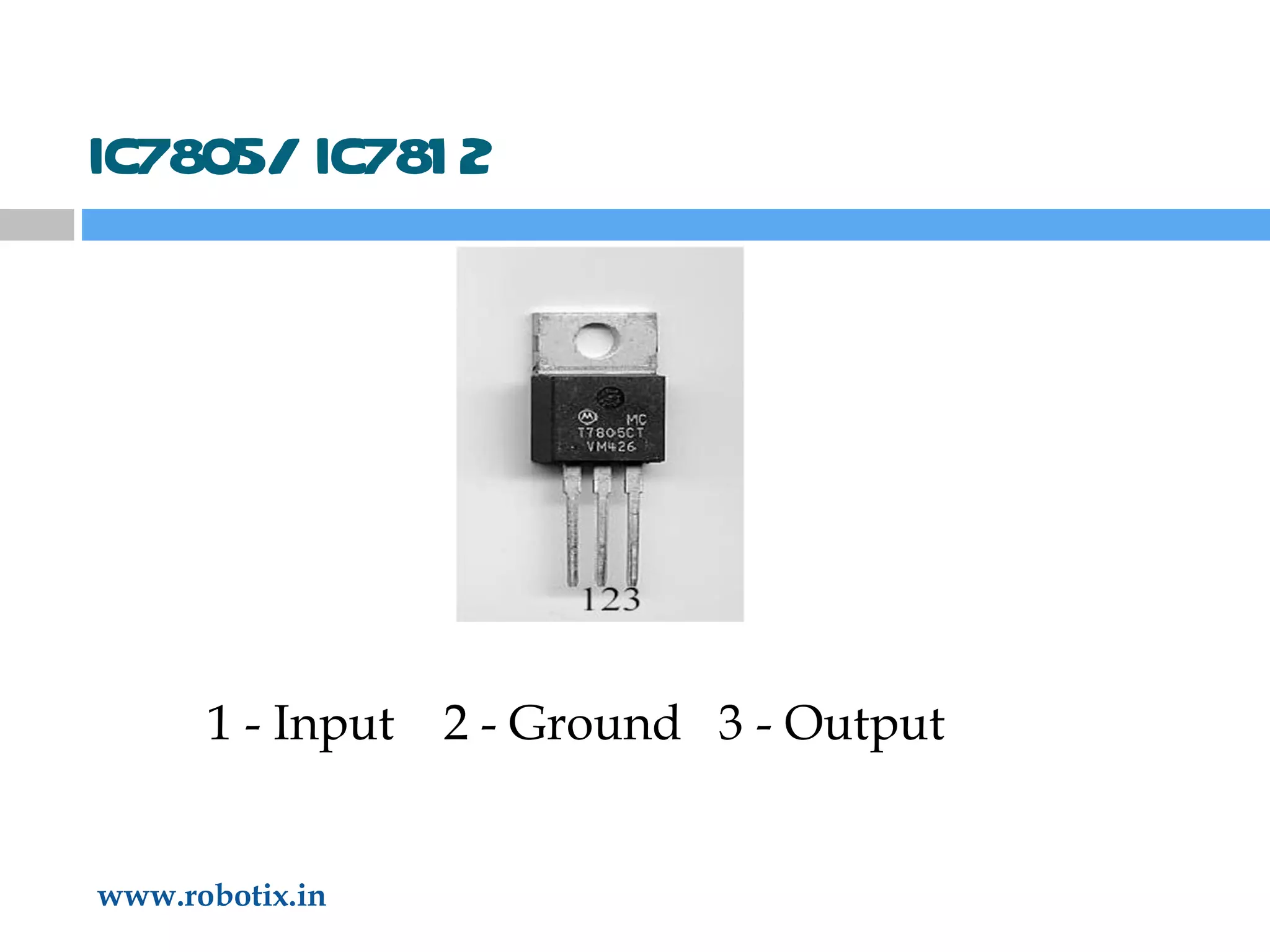
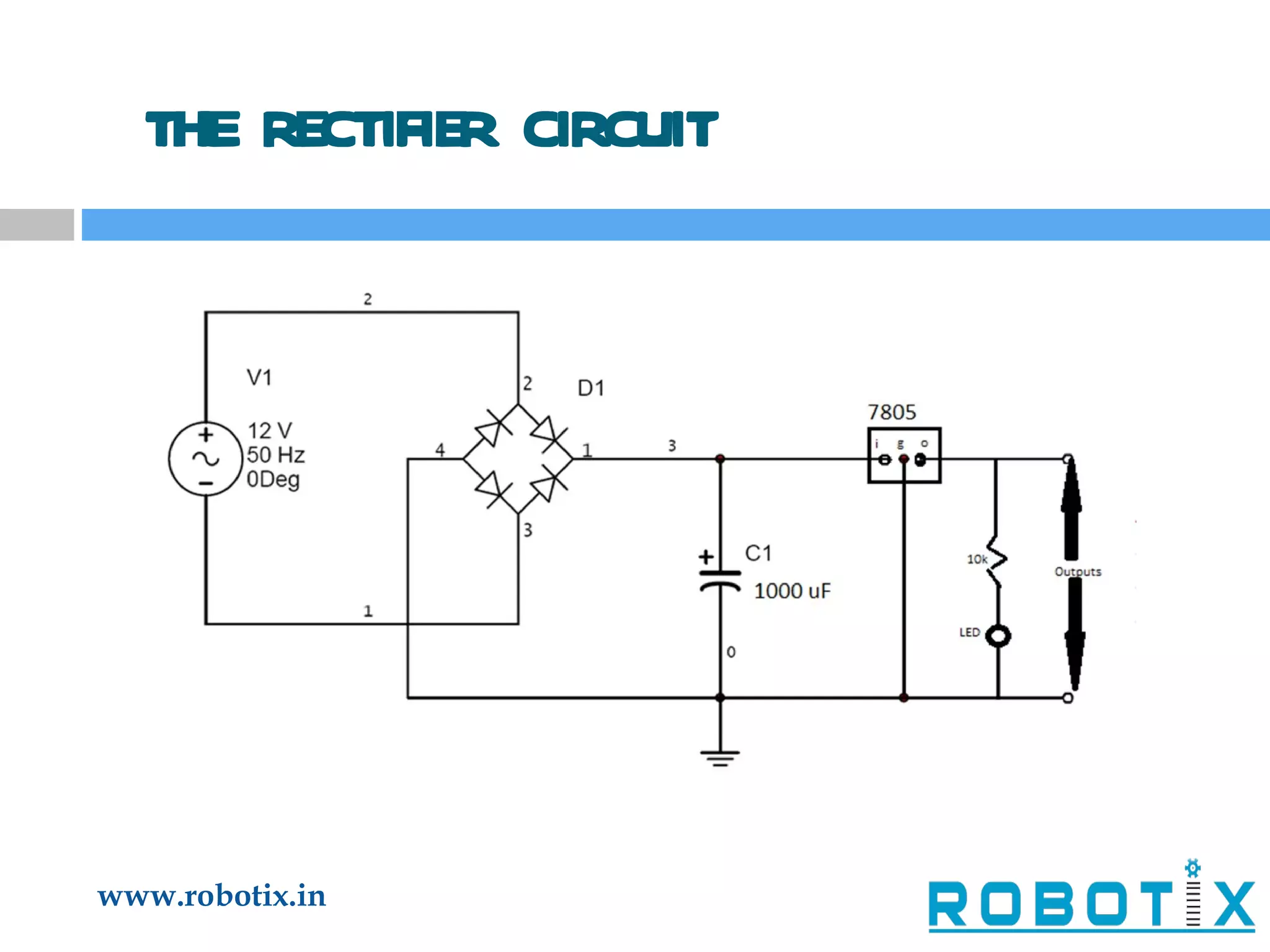
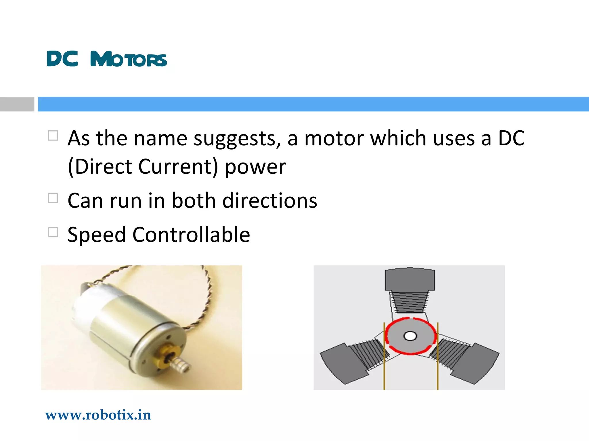
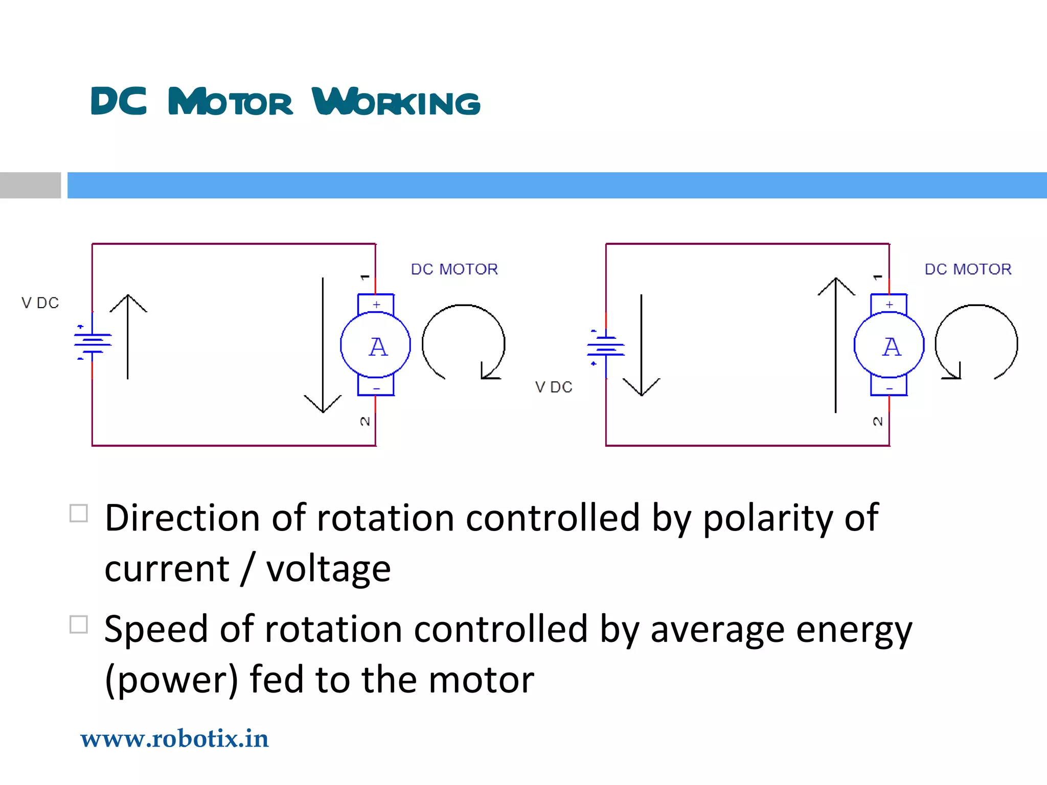
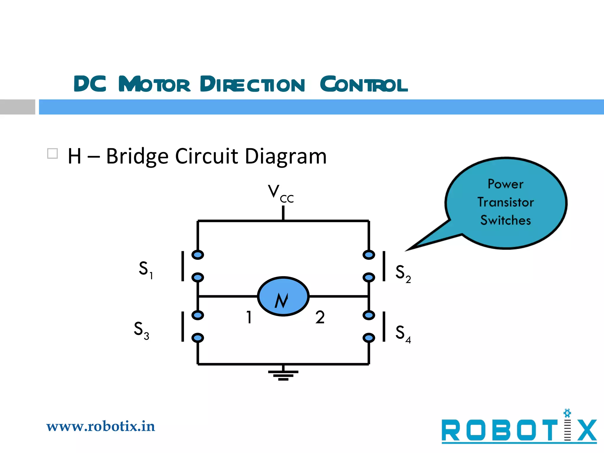
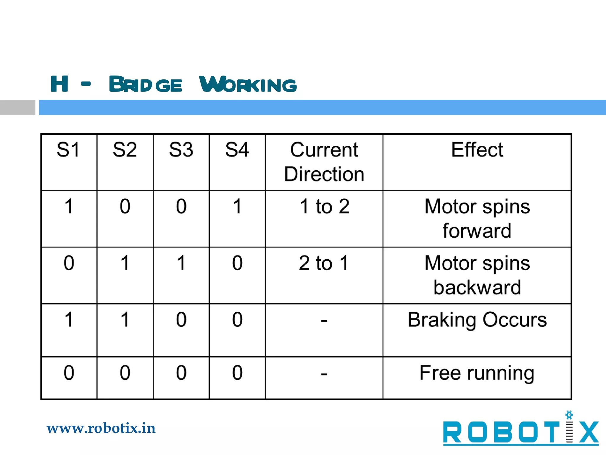
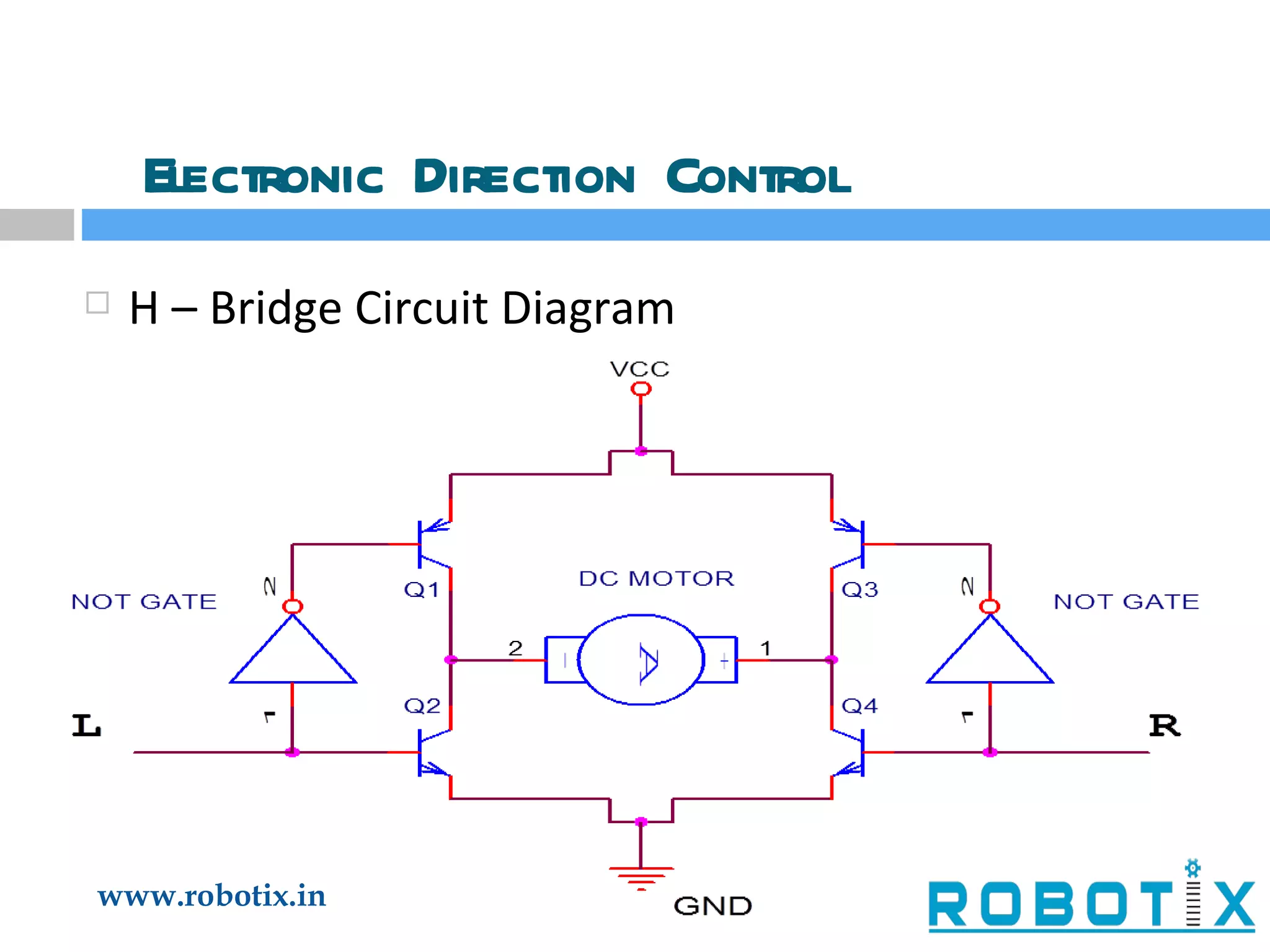
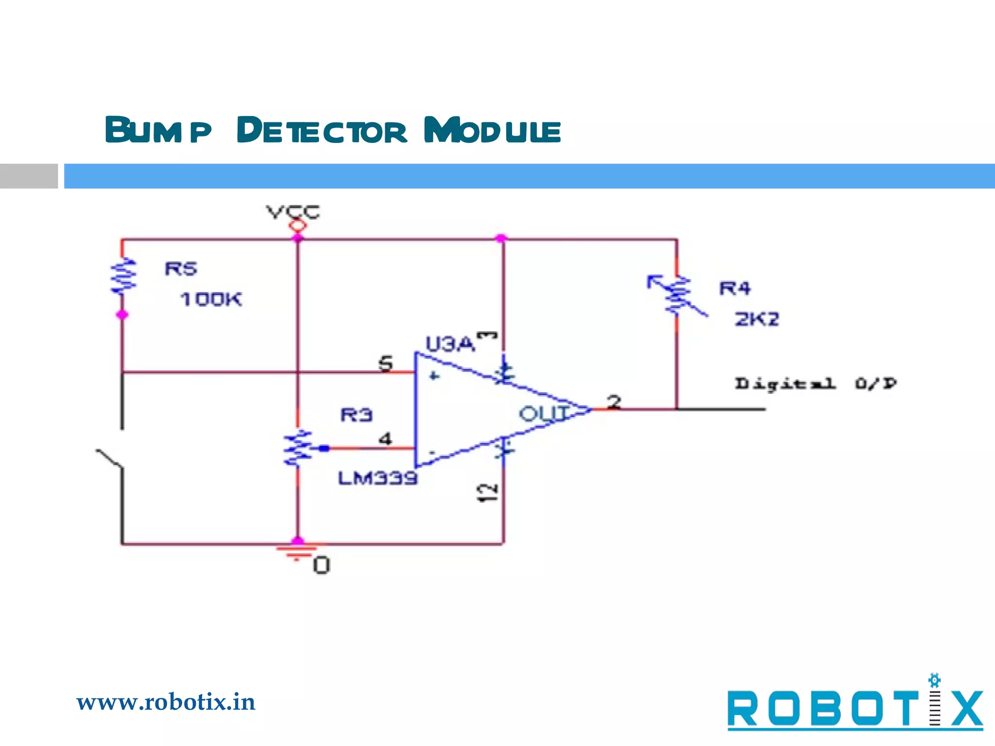
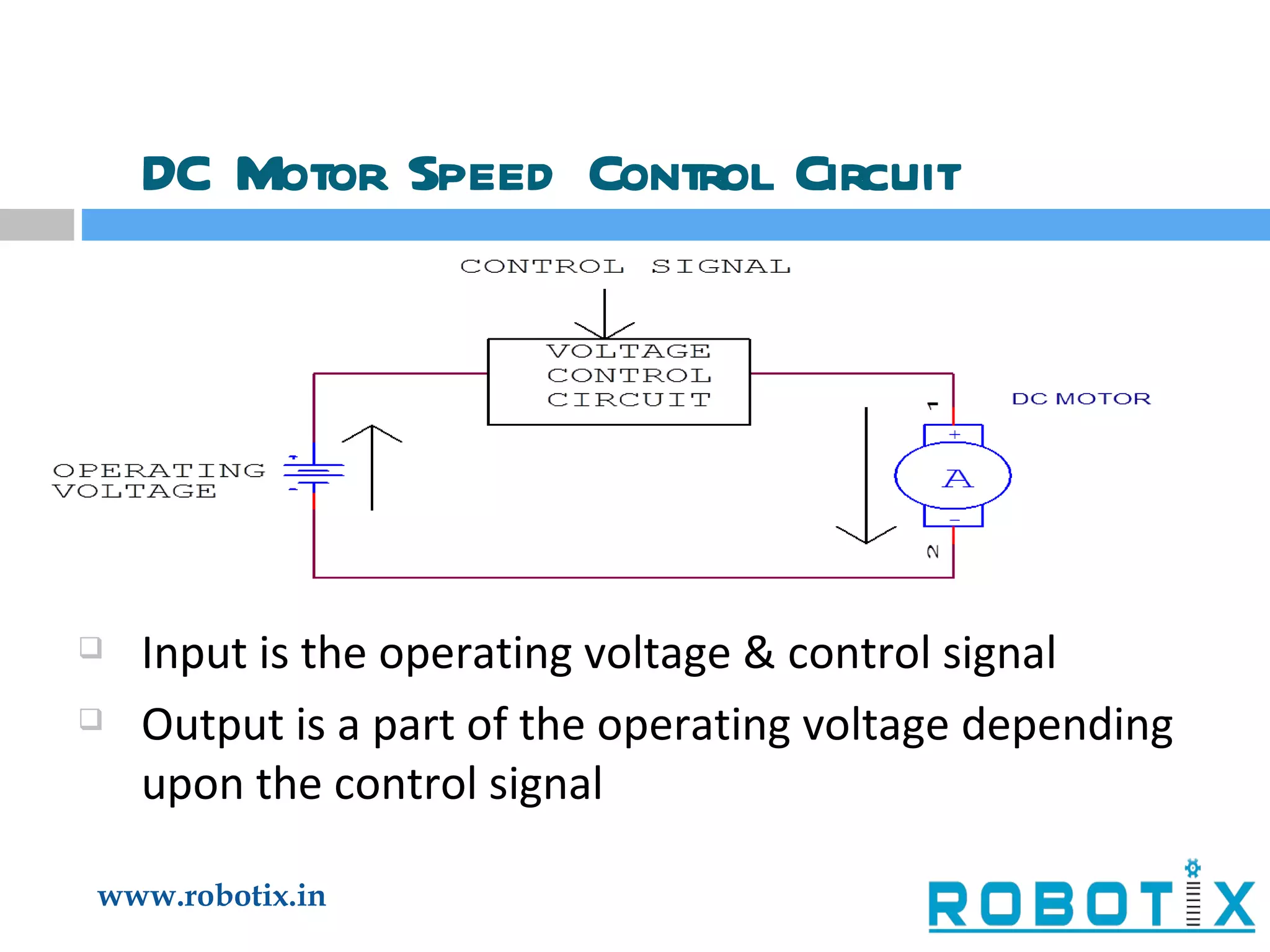
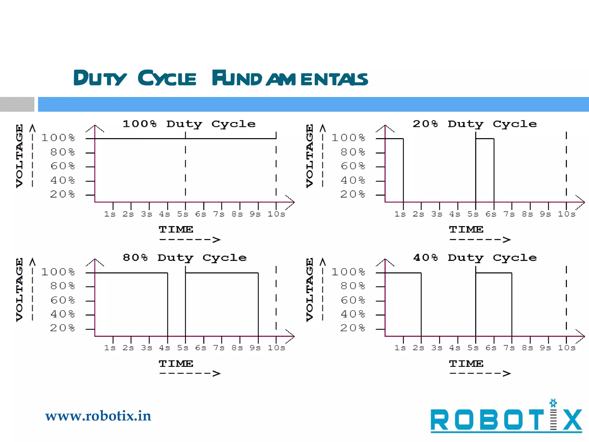
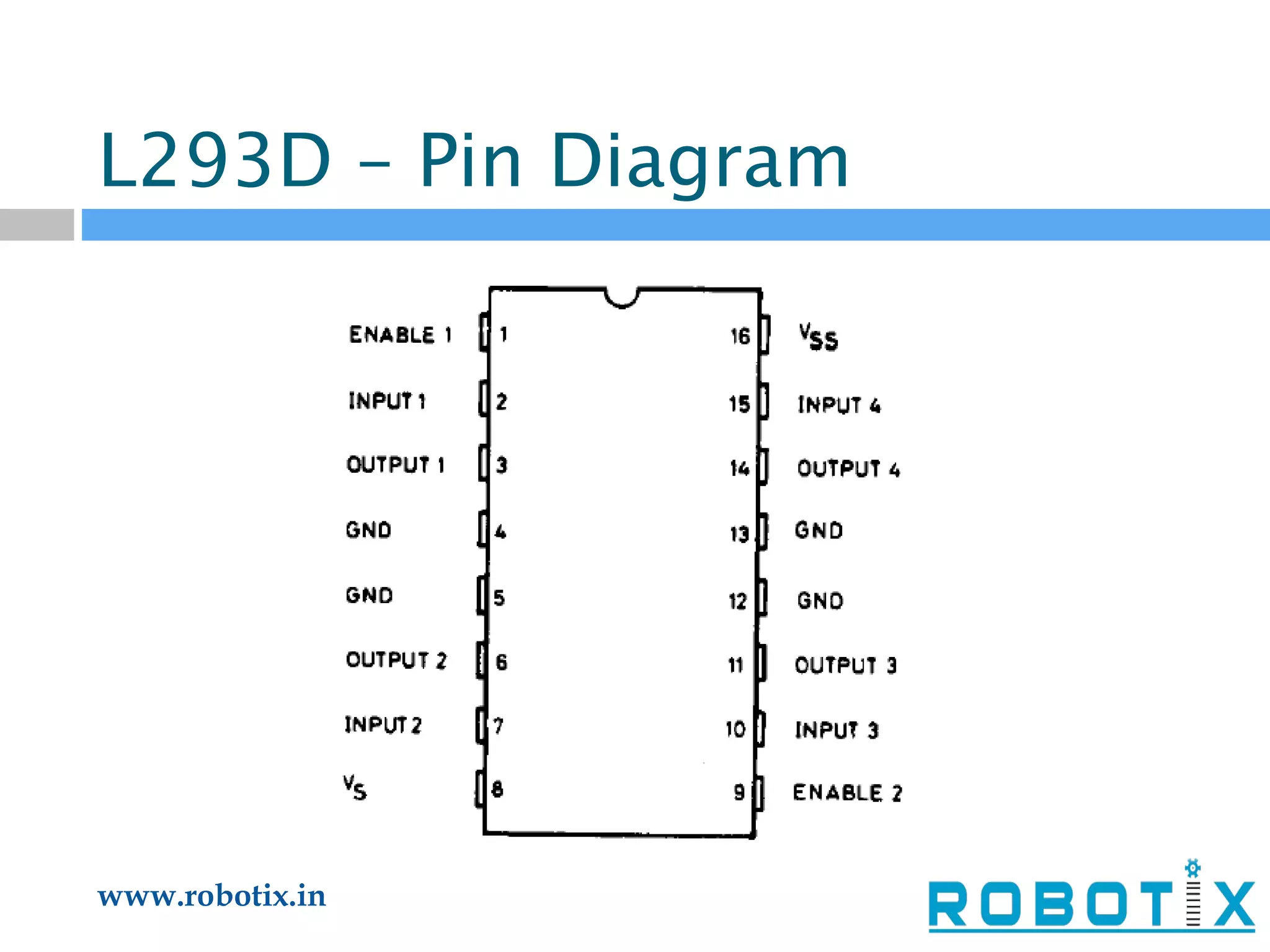
Third Fresher’s  Workshop
Basic Parts Of A Mobile Robot Locomotion system Power supply system Actuators Sensory devices for feedback Sensor Data processing unit Control system
 
Potentiometer
Capacitors
IR LED
LED: an inner view
Diode
Current Flow in a Diode
Multimeter
POWER SUPPLY  (RECTIFIER CIRCUIT)
IC7805/ IC7812 1 - Input  2 - Ground  3 - Output
THE RECTIFIER CIRCUIT
USES OF RECTIFIER CIRCUIT To convert Alternating Current to Direct Current. We get Alternating Current as Power Supply in our homes, but electronic components in robots use Direct Current.
STEPS OF CONVERTING AC TO DC First the Transformer, converts 220V AC to 12V AC. The Diodes rectify the current in a single direction. The Capacitor then normalizes the current. The little distortions are further rectified by the IC7805.
End Actuators They convert the electrical energy into meaningful mechanical work Mechanical output can be rotational or linear (straight line) Motors provide rotational motion Electromagnets provide linear motion
Motors are of various kinds AC Motors : Not used much in robotics Stepper Motors : For controlled rotation DC Motors : Finds extensive general use Servo Motors : DC motor with in built feedback & error compensation
DC Motors As the name suggests, a motor which uses a DC (Direct Current) power Can run in both directions Speed Controllable
DC Motor Working  Direction of rotation controlled by polarity of current / voltage Speed of rotation controlled by average energy (power) fed to the motor
DC Motor Specifications Operating Voltage : Recommended voltage for powering the motor Operating Current : Current drawn at a certain load on the shaft Stall Current : Maximum current drawn, when motor not allowed to rotate Stall Torque : Rotation force needed to hold the motor in stall condition
DC Motor Characteristics Free running torque & current are ideally zero Increased load implies, increased torque, current drawn & power consumption Power supplied by a motor is the product of output shaft’s rotational velocity & torque DC Motors are high–speed, low-torque devices Using gears, the high speed of the motor is traded off into torque
DC Motor Characteristics Zero speed at maximum load (stall torque) Highest speed while free running (zero load) Highest power at half speed & half load
DC Motor Drivers These are current amplifying circuits A low current control signal is converted into a proportionally higher current signal that can drive the motor Power Transistors can switch high currents. The ICmax is usually of the order of Amps as compared to small signal transistors which have ICmax in mA
DC Motor Direction Control H – Bridge Circuit Diagram S 1 S 3 S 2 S 4 M 1 2 V CC
H – Bridge Working
Electronic Direction Control H – Bridge Circuit Diagram
Sensors Analogous to human sensory organs Eyes, ears, nose, tongue, skin Sensors help the robot knowing its surroundings better Improves its actions and decision making ability Provides feedback control
LDR - Light Dependent Resistor Made of cadmium sulphide Resistance between two terminals vary depending on the intensity of light Can be used to differentiate  contrast colours
Comparator
Light Sensing Module using LED-LDR combination Sensor   Interfacing
Bump Detector Module
An Example - Line Follower A line follower is a robot capable of tracking a line drawn on a surface Optical sensors capture the line position at the front end of the robot The robot is steered to keep it always over the line
Block Layout of Line Follower
Line Following Algorithm All the sensors are assigned  some weight such as Sensor 1 = a1 = 3 Sensor 2 = a2 = 2 Sensor 3 = a3 = 1 Sensor 4 = a4 = -1 Sensor 5 = a5 = -2 Sensor 6 = a6 = -3
DC Motor Speed Control Circuit Input is the operating voltage & control signal Output is a part of the operating voltage depending upon the control signal
DC Motor Speed Control Cont… Controlling the current by passing it through a variable resistor is not advisable as it is extremely energy inefficient A trick is done to achieve reduced average power Power is supplied to the motor in short intermittent bursts, as explained further
Duty Cycle Fundamentals
Duty Cycle Contd… The time period (τ) is the duration after the voltage waveform repeats itself Duty Cycle is the % time of τ, the voltage is equal to the operating voltage The average voltage is equal to the ‘Duty Cycle’ % of the Operating Voltage
Pulse Width Modulation PWM is a technique using which we can modify the duty cycle of a waveform depending upon an input control voltage This forms the backbone of our speed control circuit It can be easily implemented using the popular multipurpose IC 555, used widely for hobby electronics
L293D – Pin Diagram
THANK YOU

Third Freshers\' Workshop 2011

  • 1.
  • 2.
    Basic Parts OfA Mobile Robot Locomotion system Power supply system Actuators Sensory devices for feedback Sensor Data processing unit Control system
  • 3.
  • 4.
  • 5.
  • 6.
  • 7.
  • 8.
  • 9.
  • 10.
  • 11.
    POWER SUPPLY (RECTIFIER CIRCUIT)
  • 12.
    IC7805/ IC7812 1- Input 2 - Ground 3 - Output
  • 13.
  • 14.
    USES OF RECTIFIERCIRCUIT To convert Alternating Current to Direct Current. We get Alternating Current as Power Supply in our homes, but electronic components in robots use Direct Current.
  • 15.
    STEPS OF CONVERTINGAC TO DC First the Transformer, converts 220V AC to 12V AC. The Diodes rectify the current in a single direction. The Capacitor then normalizes the current. The little distortions are further rectified by the IC7805.
  • 16.
    End Actuators Theyconvert the electrical energy into meaningful mechanical work Mechanical output can be rotational or linear (straight line) Motors provide rotational motion Electromagnets provide linear motion
  • 17.
    Motors are ofvarious kinds AC Motors : Not used much in robotics Stepper Motors : For controlled rotation DC Motors : Finds extensive general use Servo Motors : DC motor with in built feedback & error compensation
  • 18.
    DC Motors Asthe name suggests, a motor which uses a DC (Direct Current) power Can run in both directions Speed Controllable
  • 19.
    DC Motor Working Direction of rotation controlled by polarity of current / voltage Speed of rotation controlled by average energy (power) fed to the motor
  • 20.
    DC Motor SpecificationsOperating Voltage : Recommended voltage for powering the motor Operating Current : Current drawn at a certain load on the shaft Stall Current : Maximum current drawn, when motor not allowed to rotate Stall Torque : Rotation force needed to hold the motor in stall condition
  • 21.
    DC Motor CharacteristicsFree running torque & current are ideally zero Increased load implies, increased torque, current drawn & power consumption Power supplied by a motor is the product of output shaft’s rotational velocity & torque DC Motors are high–speed, low-torque devices Using gears, the high speed of the motor is traded off into torque
  • 22.
    DC Motor CharacteristicsZero speed at maximum load (stall torque) Highest speed while free running (zero load) Highest power at half speed & half load
  • 23.
    DC Motor DriversThese are current amplifying circuits A low current control signal is converted into a proportionally higher current signal that can drive the motor Power Transistors can switch high currents. The ICmax is usually of the order of Amps as compared to small signal transistors which have ICmax in mA
  • 24.
    DC Motor DirectionControl H – Bridge Circuit Diagram S 1 S 3 S 2 S 4 M 1 2 V CC
  • 25.
    H – BridgeWorking
  • 26.
    Electronic Direction ControlH – Bridge Circuit Diagram
  • 27.
    Sensors Analogous tohuman sensory organs Eyes, ears, nose, tongue, skin Sensors help the robot knowing its surroundings better Improves its actions and decision making ability Provides feedback control
  • 28.
    LDR - LightDependent Resistor Made of cadmium sulphide Resistance between two terminals vary depending on the intensity of light Can be used to differentiate contrast colours
  • 29.
  • 30.
    Light Sensing Moduleusing LED-LDR combination Sensor Interfacing
  • 31.
  • 32.
    An Example -Line Follower A line follower is a robot capable of tracking a line drawn on a surface Optical sensors capture the line position at the front end of the robot The robot is steered to keep it always over the line
  • 33.
    Block Layout ofLine Follower
  • 34.
    Line Following AlgorithmAll the sensors are assigned some weight such as Sensor 1 = a1 = 3 Sensor 2 = a2 = 2 Sensor 3 = a3 = 1 Sensor 4 = a4 = -1 Sensor 5 = a5 = -2 Sensor 6 = a6 = -3
  • 35.
    DC Motor SpeedControl Circuit Input is the operating voltage & control signal Output is a part of the operating voltage depending upon the control signal
  • 36.
    DC Motor SpeedControl Cont… Controlling the current by passing it through a variable resistor is not advisable as it is extremely energy inefficient A trick is done to achieve reduced average power Power is supplied to the motor in short intermittent bursts, as explained further
  • 37.
  • 38.
    Duty Cycle Contd…The time period (τ) is the duration after the voltage waveform repeats itself Duty Cycle is the % time of τ, the voltage is equal to the operating voltage The average voltage is equal to the ‘Duty Cycle’ % of the Operating Voltage
  • 39.
    Pulse Width ModulationPWM is a technique using which we can modify the duty cycle of a waveform depending upon an input control voltage This forms the backbone of our speed control circuit It can be easily implemented using the popular multipurpose IC 555, used widely for hobby electronics
  • 40.
  • 41.