Downloaded 4,499 times

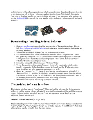
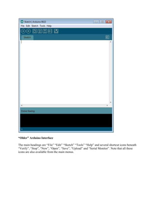
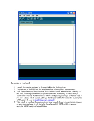
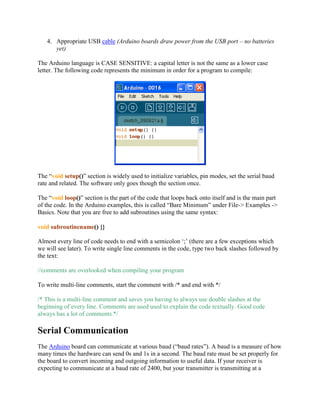
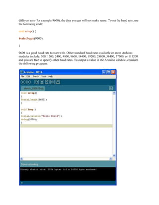
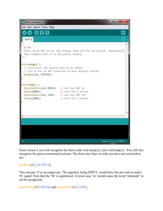
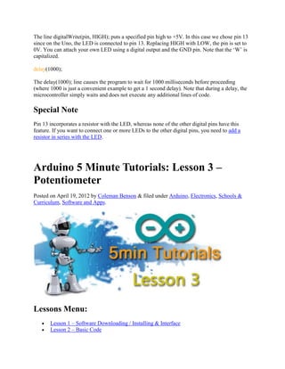
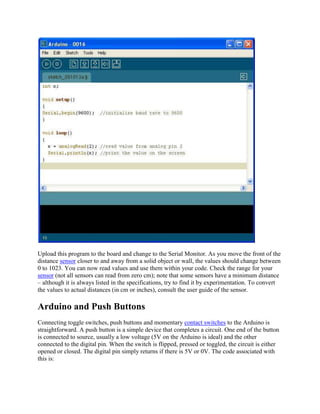
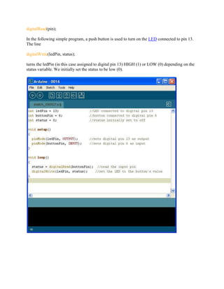
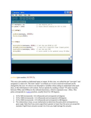

This document provides an overview and introduction to the Arduino software and programming environment through a series of tutorials. It begins by explaining how to download and install the Arduino software and interface. It then demonstrates a basic "Blink" code to turn an LED on and off as an introduction to Arduino programming. The document outlines the various sections of code, such as void setup() and void loop(), and basic syntax like semicolons. It also explains how to upload code to the Arduino board and view the output.


![Getting Started with Apache Spark: Big Data Made Simple [Free Meetup]](https://cdn.slidesharecdn.com/ss_thumbnails/apachesparkgettingstarted-260203175547-8361bcc3-thumbnail.jpg?width=640&height=640&fit=bounds)


