SlideShare a Scribd company logo
1 of 7
1
Abstract-- This project is built up to control and
monitor the speed of the three-phase induction
motor by introducing the Arduino and node MCU
controller as the key roles. Arduino is used for
implementing the pulse width modulation (PWM)
signal and the speed of the motor is controlled by
using three-phase and driver circuits. And also, in
this project the harmonics and switching losses of
the circuit will be reduced. Here, Node MCU is
used to increase and decrease the induction motor’s
speed. The feedback of the speed connection is
established to Node MCU controller and thus, the
Node MCU transfer the speed signal through Wi-
Fi.
With the help of IP address and logging into it, we
can control the speed by our self within the
permissible bandwidth of Wi-Fi.
I. INTRODUCTION
The Internet of Things (IOT) is a network of
physical objects are embedded with devices,
sensor, network connectivity are provided with
unique identifiers and the ability to automatically
collect and transfer data over a network without
requiring human-to-human or human-to-computer
interaction. IOT has evolved from the convergence
of wireless technologies, micro-electro mechanical
systems and the Internet. The internet of things
also called an Internet of objects. Online
monitoring system for continuous casting
equipment is established based on IOT sensing
technology and communication technology.
The parameters such as voltage, current, speed and
torque of induction motor were monitored. So,
input values or parameters are maintained in limits
and speed of the induction motor in a controlled
manner. IOT achieves the Industrial automation
through remote access and also increases the
operational efficiency, lower costs, and improve
productivity in automation. The various control
methods are: Field control method, Armature
control method, Ward-Leonard method. And the
new trend of controlling leading to the IOT
based
The benefits by adopting IOT are highly
automated, improves efficiency, reduce the
manual work and can be operated from various
place and Easy to access.
II. BLOCK DIAGRAM
SYSTEM HARDWARE COMPONENTS
1) Power supply
2) Step down transformer
3) Rectifier and Filter
4) Three Phase Inverter Board
5) TLP 250 Driver Board
6) Node MCU Controller
7) Arduino
8) System
9) Connecting wires
B. Sai Praneeth1
, B. Rakesh1
, K. Karthik Reddy1
, P. Jyothi Swaroop1
, J. Srinivasa Rao2
UG students1
, Associate professor2
, Department of Electrical and Electronics Engineering,
VNR VJIET, JNTU, Hyderabad, India.
SPEED CONTROL OF INDUCTION
MOTOR USING IOT
2
III. EXPLANATION OF COMPONENTS
1) POWER SUPPLY:
A Power supply used to supply the electrical  power
to the electric load. This is usually applied to
power converter which converts one form
of an electrical energy to another form
of an energy like mechanical, solar, electrical to
solar energy.
Depending on its structure, a supply can get energy
from an Electrical energy transmission system.
Different examples which convert voltages of AC
to DC  are mentioned below:
1) Energy storage devices like fuel
cells & batteries
2) Electro-mechanical devices or systems
like generators  & alternators.
3) From solar energy which is obtained from the
sun.
2) TRANSFORMER:
Step Down Transformer:
When AC is applied to the primary winding of the
power transformer it can either do stepping down
or up based on the value of DC needed. In this
circuit the transformer rating of 230v/0-12v is used
to perform the operation of step-down where a
230V AC converts into 12V AC across the
secondary winding. The top of the transformer to
be positive and the bottom negative is caused by
altering the one of the inputs. The succeeding
alteration will cause the reverse temporarily. 1A
current rating of the transformer is used in the
project and also, it gives isolation between power
supply circuits and the power source.The are used
to step down high voltages from 11000v to 220v or
110v and also from 220v or 110v to 10, 12, 20 or
24 volts etc.
The induced EMF in the secondary winding is
proportional to the number of turns on both the
primary and secondary winding's Because, of same
magnetic flux lines cut both coils of a transformer.
The secondary output voltage will be less than the
primary input voltage because the number of turns
on the secondary winding is less than the number
of turns on the primary winding. This type is called
stepdown
transformer
.
3) RECTIFIERS:
A rectifier   is a device which converts alternating 
current (AC) to direct current (DC), which flows     
in only one direction and this process is known
as rectification. Rectifiers are of different types 
like vacuum tube diodes, mercury-arc valves,   
copper and selenium oxide
rectifiers, semiconductor diodes, silicon-   
controlled rectifiers and other silicon-based 
semiconductor switches.
Rectifiers have numerous uses, but are found
working as components of DC power 
supplies and high-voltage direct current power     
transmission systems.
In a center tapped full wave rectifier, both
positive and negative half cycles are rectified.
So, no voltage is wasted at the output.
Furthermore, the DC output produced by center
tapped half wave rectifier is less smoother than
the full wave rectifier output
FILTERING UNIT:
Filter circuits which are capacitors acts as a
surge arrester and always follow the rectifier
unit. This is also called as a bypassing capacitor
or decoupling capacitor. It is used not used to
leave the frequency of the DC to appear at the
output but also to ‘short’ the ripple with
frequency of 120Hz to ground. A load resistor
R1 is connected so that a reference to the ground
is maintained. C2R2 is used as a low pass filter,
C1R1 is for bypassing ripples i.e. it passes only
low frequency signals and bypasses high
frequency signals. The load resistor should be
1% to 2.5% of the load.
O, 1Ω f: It is for bypassing the high frequency
disturbances.
10Ω f/25v: It is for maintaining the stability of
the voltage at the load side.
1000Ω f/25v: It is for the reduction of ripples
from the pulsating.
3
4) Three Phase Voltage Source Inverters
Single-phase VSIs and three phase VSIs covers
low-range power and high- range applications
respectively. The main purpose of these concepts is
to provide a 3-phase voltage source, where the
voltage, phase, amplitude of the voltages should
always control and also most of the applications
require sinusoidal voltage waveforms, arbitrary
voltages are also required in some emerging
applications like active filters, voltage
compensators.
A) SINUSOIDAL PULSE WIDTH
MODULATION
In Power electronics, The Sinusoidal Pulse Width
Modulation (SPWM) is a well-known as wave
shaping technique for realization, a high frequency
triangular carrier signal, V1 is compared with a
sinusoidal reference signal V of the desired
frequency. Modulation index is the magnitude ratio
of the reference signal (Vr,) to that of triangular
signal (Vc).
B) PULSE WIDTH MODULATION
When a PWM signal is given to the gate of a
power transistor then it causes the turn on and
turns off intervals to change from one PWM
period to another PWM period according to the
same modulating signal. The frequency of a
modulating signal is much lower than the
PWM signal. So, the energy and its load of the
motor depends mostly on the modulating
signal
5) DRIVER CIRCUIT COMPONENTS
Below mentioned components are used to
amplify and triggering the pulses. They are:
1)OPTOCOUPLER
2) BUFFER IC
3) TRANSISTOR
OPTOCOUPLER:
Optocouplers normally in a small 6-pin or 8-
pin IC package, however are basically a mix of
two distinct devices an optical transmitter,
typically a gallium arsenide LED and an
optical receiver, like a photo-transistor or light-
triggered diac. These two are isolated by a
transparent barrier which obstructs any
electrical flow between the two, however
allows the passage of light. The essential
thought is appeared in Fig.1, alongside the
standard circuit image for an optocoupler.
BUFFER IC –CD4050:
The CD4050BC hex buffers are monolithic
complementary MOS (CMOS) incorporated
circuits built with N-and P-channel
enhancement-mode transistors. These devices
high light logic level conversion utilizing just a
single supply voltage (VDD). The input signal
high level (VIH) can exceeds the VDD supply
voltage when these devices are utilized for logic
level conversions. These devices are planned for
use as hex buffers, CMOS to DTL/TTL
converters
6) Node MCU:
Node MCU is an opensource IoT platform,   
which includes firmware which keeps running   
on the ESP8266 Wi-Fi SoC from Espress if         
Systems, and equipment which depends on the
ESP12 module. The term Node MCU naturally 
relates to the firmware instead of the
development kits. The firmware utilizes
the Lua scripting language which is based on   
the eLua project, and based on the Espress if
Non-OS SDK for ESP8266. It utilizes many
open source ventures, for example, lua-
cjson and SPIFFS.   
7) ARDUINO/EMBEDDEDSYSTEMS
4
An embedded system is a special-purpose
computer system designed to perform one or a few
dedicated functions, often with real-time
computing constraints. It is usually embedded as
part of a complete device including hardware and
mechanical parts. In contrast, a general-purpose
computer, such as a personal computer, can do
many different tasks depending on programming.
Embedded systems have become very important
today as they control many of the common devices
we use.
7) SYSTEM:
A PC framework enables clients to enter, control
and store information. PC frameworks normally
incorporate a PC, screen, console, mouse and other
optional components. Yes, you need a PC to
program Arduino. once programmed, it will run
without the PC. The Arduino isn't powerful enough
to run software. You would normally connect it
via the network / internet to a server to process
data
8) CONNECTING WIRES:
connecting wires enables an electrical current to
go from one point on a circuit then onto the next
that because power needs a medium through
which it can move. The vast majority of the
connecting wires are comprised of copper or
aluminum. Copper is cheap and great
conductivity. Rather than the copper, we can
likewise utilize silver which has high
conductivity however it is too costly to even
think about using.
CONNECTION BETWEEN ARDUINO-
DRIVER CIRCUIT - NODE MCU
III. MATLAB SIMULATION FOR 3-PHASE
VOLTAGE SOURCE INVERTER
(180 DEGRESS CONDUCTION MODE)
IV. HARDWARE IMPLEMENTATION
MATLAB/ SIMULATION RESULT:
5
HARWARE RESULT :
V. CONCLUSION
This project results the design and implementation
of Internet of things for control the function of the
3-phase motor using technique of wireless
communication. The major idea is long-distance
connectivity between location of the machine and
user and also to provide flexible. The major
advantages of the developed system are to have a
continuous monitoring over industrial applications
and also providing e for agricultural application
which control the induction motor. This work is
mainly focused on the improvement of a reliable
smart Industrial monitoring and controlling system.
By this efficiency of the system can be further
improved.
VI. REFERENCES
[1] “remote controlling and monitoring of
induction motors using internet”, abdulkadir, cakır,
hakan cali’s, gokhan turan suleiman demirel
university, faculty of technology, department of
electrical and electronic engineering, isparta
turkey(2014).
[2] “Real-Time Monitoring and Control of the
Parameters of an Induction Motor", Department
Of Electrical and Electronics Engineering,
Technology of Faculty, Gazi
UniversityTeknikokullar Ankara, Turkey .
[3] Woodford, “induction motors”, [online].
Available:
http://www.explainthatstuff.com/induction-
motors.html. [accessed: 4- november- 2015].
[4] “Research on remote wireless monitoring
system based on GPRS and MCU” , Zhong-
Xuan, J. Xiau-Yu, H. Zhao-Fu, Z. Yan-Tao, D.
Meng,Int. Conf. Computational Problem
Solving ICCP 2010, Lijiang, China, Dec.
[5]. J. S. Hsu and A. M. A. Amin, “Torque
calculations of current-source Induction
machines using the 1-2-0 coordinate system,”
IEEE Trans. Ind.Electron. vol. 37, no. 1, pp. 34–
40, Feb. 1990.
[6]. Shamsul Aizam Zulkifli, Mohd Najib
Hussin, Abdul Salam Saad “MATLAB Arduino
as a Low Cost Microcontroller for 3 phase
inverter” 978-1- 4799-6428- 4/14/$31.00 ©2014
IEEE.
[7] S.-J. Park, F.-S. Kang, M. H. Lee, and C.-U.
Kim, “A new single-phase five-level PWM
inverter employing a deadbeat control scheme,”
IEEE Trans. Power Electron., vol. 18, no. 3, pp.
831–843, May 2003.
[8] Y. Hinago and H. Koizumi, “A switched-
capacitor inverter using series/ parallel
conversion with inductive load,” IEEE Trans.
Ind. Electron., vol. 59, no. 2, pp. 878–887, Feb.
2012.
6
6

More Related Content

What's hot

UltraCapacitor
UltraCapacitorUltraCapacitor
UltraCapacitordhimancool
 
Electric drives control
Electric drives controlElectric drives control
Electric drives controlAnandKumar2123
 
Solid State Control of Electric Drive
Solid State Control of Electric DriveSolid State Control of Electric Drive
Solid State Control of Electric DriveSHIMI S L
 
Synchronous motor drive
Synchronous motor driveSynchronous motor drive
Synchronous motor driveGuru Moorthi
 
High Voltage Direct Current Transmission System
High Voltage Direct Current Transmission SystemHigh Voltage Direct Current Transmission System
High Voltage Direct Current Transmission SystemNadeem Khilji
 
Three phase voltage source inverter
Three phase voltage source inverterThree phase voltage source inverter
Three phase voltage source invertertamilnesaner
 
Drives lec 21_22_Chopper Controlled DC Drives
Drives lec 21_22_Chopper Controlled DC DrivesDrives lec 21_22_Chopper Controlled DC Drives
Drives lec 21_22_Chopper Controlled DC DrivesMohammad Umar Rehman
 
vector control of induction motor
vector control of induction motorvector control of induction motor
vector control of induction motorDwaraka Pilla
 
Flexible ac transmission system
Flexible ac transmission systemFlexible ac transmission system
Flexible ac transmission systemUday Wankar
 
Vector control of pmsm
Vector control of pmsmVector control of pmsm
Vector control of pmsmMalarselvamV
 
Brushless dc motor
Brushless dc motorBrushless dc motor
Brushless dc motorBiplab Nayak
 
Module 3 electric propulsion electric vehicle technology ppt
Module 3 electric propulsion   electric vehicle technology pptModule 3 electric propulsion   electric vehicle technology ppt
Module 3 electric propulsion electric vehicle technology pptDrCVMOHAN
 

What's hot (20)

Classes of motor duty
Classes of motor dutyClasses of motor duty
Classes of motor duty
 
UltraCapacitor
UltraCapacitorUltraCapacitor
UltraCapacitor
 
Electric drives control
Electric drives controlElectric drives control
Electric drives control
 
Chapter5
Chapter5Chapter5
Chapter5
 
Solid State Control of Electric Drive
Solid State Control of Electric DriveSolid State Control of Electric Drive
Solid State Control of Electric Drive
 
Synchronous motor drive
Synchronous motor driveSynchronous motor drive
Synchronous motor drive
 
High Voltage Direct Current Transmission System
High Voltage Direct Current Transmission SystemHigh Voltage Direct Current Transmission System
High Voltage Direct Current Transmission System
 
Three phase voltage source inverter
Three phase voltage source inverterThree phase voltage source inverter
Three phase voltage source inverter
 
Reluctance motor
Reluctance  motor Reluctance  motor
Reluctance motor
 
Drives lec 21_22_Chopper Controlled DC Drives
Drives lec 21_22_Chopper Controlled DC DrivesDrives lec 21_22_Chopper Controlled DC Drives
Drives lec 21_22_Chopper Controlled DC Drives
 
Tap changer
Tap changerTap changer
Tap changer
 
vector control of induction motor
vector control of induction motorvector control of induction motor
vector control of induction motor
 
Flexible ac transmission system
Flexible ac transmission systemFlexible ac transmission system
Flexible ac transmission system
 
Vector control of pmsm
Vector control of pmsmVector control of pmsm
Vector control of pmsm
 
Stepper motor
Stepper motorStepper motor
Stepper motor
 
HVDC vs HVAC ppt
HVDC vs HVAC pptHVDC vs HVAC ppt
HVDC vs HVAC ppt
 
Inverter
InverterInverter
Inverter
 
Brushless dc motor
Brushless dc motorBrushless dc motor
Brushless dc motor
 
Module 3 electric propulsion electric vehicle technology ppt
Module 3 electric propulsion   electric vehicle technology pptModule 3 electric propulsion   electric vehicle technology ppt
Module 3 electric propulsion electric vehicle technology ppt
 
Tap Changer
Tap ChangerTap Changer
Tap Changer
 

Similar to Control Induction Motor Speed using IOT

Gsm based smart card information for lost atm cards
Gsm based smart card information for lost atm cardsGsm based smart card information for lost atm cards
Gsm based smart card information for lost atm cardsSomanchi Aditya
 
Proposal on Power Theft
Proposal on Power TheftProposal on Power Theft
Proposal on Power TheftAneel-k Suthar
 
Pwm generation to control variable frequency power source
Pwm generation to control variable frequency power sourcePwm generation to control variable frequency power source
Pwm generation to control variable frequency power sourceeSAT Publishing House
 
3) Remote Controlled Fan Regulator
3) Remote Controlled Fan Regulator3) Remote Controlled Fan Regulator
3) Remote Controlled Fan Regulatorsajin sr
 
Gsm based garbage disposal
Gsm based garbage disposalGsm based garbage disposal
Gsm based garbage disposalSuhanthi Devraj
 
SECURED WIRELESS POWER TRANSMISSION USING RADIO FREQUENCY SIGNAL
SECURED WIRELESS POWER TRANSMISSION USING RADIO FREQUENCY SIGNALSECURED WIRELESS POWER TRANSMISSION USING RADIO FREQUENCY SIGNAL
SECURED WIRELESS POWER TRANSMISSION USING RADIO FREQUENCY SIGNALijistjournal
 
Secured wireless power
Secured wireless powerSecured wireless power
Secured wireless powerijistjournal
 
Design of wireless sensor network for building management systems
Design of wireless sensor network for building management systemsDesign of wireless sensor network for building management systems
Design of wireless sensor network for building management systemsTSriyaSharma
 
Automatic temperature base fan controlle
Automatic temperature base fan  controlleAutomatic temperature base fan  controlle
Automatic temperature base fan controlleDharmaraj Morle
 
Tunnel robot ppt
Tunnel robot pptTunnel robot ppt
Tunnel robot pptshakshi58
 
A DAPTIVE S UPPLY V OLTAGE M ANAGEMENT F OR L OW P OWER L OGIC C IRCU...
A DAPTIVE  S UPPLY  V OLTAGE  M ANAGEMENT  F OR  L OW  P OWER  L OGIC  C IRCU...A DAPTIVE  S UPPLY  V OLTAGE  M ANAGEMENT  F OR  L OW  P OWER  L OGIC  C IRCU...
A DAPTIVE S UPPLY V OLTAGE M ANAGEMENT F OR L OW P OWER L OGIC C IRCU...VLSICS Design
 
DC MOTOR SPEED CONTROL USING ON-OFF CONTROLLER BY PIC16F877A MICROCONTROLLER
DC MOTOR SPEED CONTROL USING ON-OFF CONTROLLER BY  PIC16F877A MICROCONTROLLERDC MOTOR SPEED CONTROL USING ON-OFF CONTROLLER BY  PIC16F877A MICROCONTROLLER
DC MOTOR SPEED CONTROL USING ON-OFF CONTROLLER BY PIC16F877A MICROCONTROLLERTridib Bose
 
Data Transmission Through Inductive Coupled System
Data Transmission Through Inductive Coupled SystemData Transmission Through Inductive Coupled System
Data Transmission Through Inductive Coupled SystemIRJET Journal
 
RAJPRASAD PAPER NO-127
RAJPRASAD PAPER NO-127RAJPRASAD PAPER NO-127
RAJPRASAD PAPER NO-127RAJPRASAD RS
 
Tracking and breaking system for vehicles
Tracking and breaking system for vehiclesTracking and breaking system for vehicles
Tracking and breaking system for vehicleskakanikings
 
IRJET- Design and Implementaion of DC-DC Boost Converter using Output Voltage...
IRJET- Design and Implementaion of DC-DC Boost Converter using Output Voltage...IRJET- Design and Implementaion of DC-DC Boost Converter using Output Voltage...
IRJET- Design and Implementaion of DC-DC Boost Converter using Output Voltage...IRJET Journal
 
“Microcontroller Based Substation Monitoring system with gsm modem”.
“Microcontroller Based Substation Monitoring system with gsm modem”.“Microcontroller Based Substation Monitoring system with gsm modem”.
“Microcontroller Based Substation Monitoring system with gsm modem”.Priya Rachakonda
 

Similar to Control Induction Motor Speed using IOT (20)

Automatic mall elevator
Automatic mall elevatorAutomatic mall elevator
Automatic mall elevator
 
Gsm based smart card information for lost atm cards
Gsm based smart card information for lost atm cardsGsm based smart card information for lost atm cards
Gsm based smart card information for lost atm cards
 
Proposal on Power Theft
Proposal on Power TheftProposal on Power Theft
Proposal on Power Theft
 
Pwm generation to control variable frequency power source
Pwm generation to control variable frequency power sourcePwm generation to control variable frequency power source
Pwm generation to control variable frequency power source
 
3) Remote Controlled Fan Regulator
3) Remote Controlled Fan Regulator3) Remote Controlled Fan Regulator
3) Remote Controlled Fan Regulator
 
Gsm based garbage disposal
Gsm based garbage disposalGsm based garbage disposal
Gsm based garbage disposal
 
SECURED WIRELESS POWER TRANSMISSION USING RADIO FREQUENCY SIGNAL
SECURED WIRELESS POWER TRANSMISSION USING RADIO FREQUENCY SIGNALSECURED WIRELESS POWER TRANSMISSION USING RADIO FREQUENCY SIGNAL
SECURED WIRELESS POWER TRANSMISSION USING RADIO FREQUENCY SIGNAL
 
Secured wireless power
Secured wireless powerSecured wireless power
Secured wireless power
 
Design of wireless sensor network for building management systems
Design of wireless sensor network for building management systemsDesign of wireless sensor network for building management systems
Design of wireless sensor network for building management systems
 
Automatic temperature base fan controlle
Automatic temperature base fan  controlleAutomatic temperature base fan  controlle
Automatic temperature base fan controlle
 
Tunnel robot ppt
Tunnel robot pptTunnel robot ppt
Tunnel robot ppt
 
A DAPTIVE S UPPLY V OLTAGE M ANAGEMENT F OR L OW P OWER L OGIC C IRCU...
A DAPTIVE  S UPPLY  V OLTAGE  M ANAGEMENT  F OR  L OW  P OWER  L OGIC  C IRCU...A DAPTIVE  S UPPLY  V OLTAGE  M ANAGEMENT  F OR  L OW  P OWER  L OGIC  C IRCU...
A DAPTIVE S UPPLY V OLTAGE M ANAGEMENT F OR L OW P OWER L OGIC C IRCU...
 
3.3V DC output at -16dBm sensitivity and 77% PCE rectifier for RF energy harv...
3.3V DC output at -16dBm sensitivity and 77% PCE rectifier for RF energy harv...3.3V DC output at -16dBm sensitivity and 77% PCE rectifier for RF energy harv...
3.3V DC output at -16dBm sensitivity and 77% PCE rectifier for RF energy harv...
 
DC MOTOR SPEED CONTROL USING ON-OFF CONTROLLER BY PIC16F877A MICROCONTROLLER
DC MOTOR SPEED CONTROL USING ON-OFF CONTROLLER BY  PIC16F877A MICROCONTROLLERDC MOTOR SPEED CONTROL USING ON-OFF CONTROLLER BY  PIC16F877A MICROCONTROLLER
DC MOTOR SPEED CONTROL USING ON-OFF CONTROLLER BY PIC16F877A MICROCONTROLLER
 
Data Transmission Through Inductive Coupled System
Data Transmission Through Inductive Coupled SystemData Transmission Through Inductive Coupled System
Data Transmission Through Inductive Coupled System
 
03 TOTAL REPORT
03 TOTAL REPORT03 TOTAL REPORT
03 TOTAL REPORT
 
RAJPRASAD PAPER NO-127
RAJPRASAD PAPER NO-127RAJPRASAD PAPER NO-127
RAJPRASAD PAPER NO-127
 
Tracking and breaking system for vehicles
Tracking and breaking system for vehiclesTracking and breaking system for vehicles
Tracking and breaking system for vehicles
 
IRJET- Design and Implementaion of DC-DC Boost Converter using Output Voltage...
IRJET- Design and Implementaion of DC-DC Boost Converter using Output Voltage...IRJET- Design and Implementaion of DC-DC Boost Converter using Output Voltage...
IRJET- Design and Implementaion of DC-DC Boost Converter using Output Voltage...
 
“Microcontroller Based Substation Monitoring system with gsm modem”.
“Microcontroller Based Substation Monitoring system with gsm modem”.“Microcontroller Based Substation Monitoring system with gsm modem”.
“Microcontroller Based Substation Monitoring system with gsm modem”.
 

Recently uploaded

Heart Disease Prediction using machine learning.pptx
Heart Disease Prediction using machine learning.pptxHeart Disease Prediction using machine learning.pptx
Heart Disease Prediction using machine learning.pptxPoojaBan
 
Call Girls Narol 7397865700 Independent Call Girls
Call Girls Narol 7397865700 Independent Call GirlsCall Girls Narol 7397865700 Independent Call Girls
Call Girls Narol 7397865700 Independent Call Girlsssuser7cb4ff
 
Application of Residue Theorem to evaluate real integrations.pptx
Application of Residue Theorem to evaluate real integrations.pptxApplication of Residue Theorem to evaluate real integrations.pptx
Application of Residue Theorem to evaluate real integrations.pptx959SahilShah
 
Risk Assessment For Installation of Drainage Pipes.pdf
Risk Assessment For Installation of Drainage Pipes.pdfRisk Assessment For Installation of Drainage Pipes.pdf
Risk Assessment For Installation of Drainage Pipes.pdfROCENODodongVILLACER
 
Electronically Controlled suspensions system .pdf
Electronically Controlled suspensions system .pdfElectronically Controlled suspensions system .pdf
Electronically Controlled suspensions system .pdfme23b1001
 
Study on Air-Water & Water-Water Heat Exchange in a Finned Tube Exchanger
Study on Air-Water & Water-Water Heat Exchange in a Finned Tube ExchangerStudy on Air-Water & Water-Water Heat Exchange in a Finned Tube Exchanger
Study on Air-Water & Water-Water Heat Exchange in a Finned Tube ExchangerAnamika Sarkar
 
Oxy acetylene welding presentation note.
Oxy acetylene welding presentation note.Oxy acetylene welding presentation note.
Oxy acetylene welding presentation note.eptoze12
 
Biology for Computer Engineers Course Handout.pptx
Biology for Computer Engineers Course Handout.pptxBiology for Computer Engineers Course Handout.pptx
Biology for Computer Engineers Course Handout.pptxDeepakSakkari2
 
computer application and construction management
computer application and construction managementcomputer application and construction management
computer application and construction managementMariconPadriquez1
 
INFLUENCE OF NANOSILICA ON THE PROPERTIES OF CONCRETE
INFLUENCE OF NANOSILICA ON THE PROPERTIES OF CONCRETEINFLUENCE OF NANOSILICA ON THE PROPERTIES OF CONCRETE
INFLUENCE OF NANOSILICA ON THE PROPERTIES OF CONCRETEroselinkalist12
 
What are the advantages and disadvantages of membrane structures.pptx
What are the advantages and disadvantages of membrane structures.pptxWhat are the advantages and disadvantages of membrane structures.pptx
What are the advantages and disadvantages of membrane structures.pptxwendy cai
 
IVE Industry Focused Event - Defence Sector 2024
IVE Industry Focused Event - Defence Sector 2024IVE Industry Focused Event - Defence Sector 2024
IVE Industry Focused Event - Defence Sector 2024Mark Billinghurst
 
Correctly Loading Incremental Data at Scale
Correctly Loading Incremental Data at ScaleCorrectly Loading Incremental Data at Scale
Correctly Loading Incremental Data at ScaleAlluxio, Inc.
 
Churning of Butter, Factors affecting .
Churning of Butter, Factors affecting  .Churning of Butter, Factors affecting  .
Churning of Butter, Factors affecting .Satyam Kumar
 
main PPT.pptx of girls hostel security using rfid
main PPT.pptx of girls hostel security using rfidmain PPT.pptx of girls hostel security using rfid
main PPT.pptx of girls hostel security using rfidNikhilNagaraju
 
Arduino_CSE ece ppt for working and principal of arduino.ppt
Arduino_CSE ece ppt for working and principal of arduino.pptArduino_CSE ece ppt for working and principal of arduino.ppt
Arduino_CSE ece ppt for working and principal of arduino.pptSAURABHKUMAR892774
 
Why does (not) Kafka need fsync: Eliminating tail latency spikes caused by fsync
Why does (not) Kafka need fsync: Eliminating tail latency spikes caused by fsyncWhy does (not) Kafka need fsync: Eliminating tail latency spikes caused by fsync
Why does (not) Kafka need fsync: Eliminating tail latency spikes caused by fsyncssuser2ae721
 

Recently uploaded (20)

Heart Disease Prediction using machine learning.pptx
Heart Disease Prediction using machine learning.pptxHeart Disease Prediction using machine learning.pptx
Heart Disease Prediction using machine learning.pptx
 
Call Girls Narol 7397865700 Independent Call Girls
Call Girls Narol 7397865700 Independent Call GirlsCall Girls Narol 7397865700 Independent Call Girls
Call Girls Narol 7397865700 Independent Call Girls
 
Application of Residue Theorem to evaluate real integrations.pptx
Application of Residue Theorem to evaluate real integrations.pptxApplication of Residue Theorem to evaluate real integrations.pptx
Application of Residue Theorem to evaluate real integrations.pptx
 
Risk Assessment For Installation of Drainage Pipes.pdf
Risk Assessment For Installation of Drainage Pipes.pdfRisk Assessment For Installation of Drainage Pipes.pdf
Risk Assessment For Installation of Drainage Pipes.pdf
 
Electronically Controlled suspensions system .pdf
Electronically Controlled suspensions system .pdfElectronically Controlled suspensions system .pdf
Electronically Controlled suspensions system .pdf
 
Study on Air-Water & Water-Water Heat Exchange in a Finned Tube Exchanger
Study on Air-Water & Water-Water Heat Exchange in a Finned Tube ExchangerStudy on Air-Water & Water-Water Heat Exchange in a Finned Tube Exchanger
Study on Air-Water & Water-Water Heat Exchange in a Finned Tube Exchanger
 
Oxy acetylene welding presentation note.
Oxy acetylene welding presentation note.Oxy acetylene welding presentation note.
Oxy acetylene welding presentation note.
 
Biology for Computer Engineers Course Handout.pptx
Biology for Computer Engineers Course Handout.pptxBiology for Computer Engineers Course Handout.pptx
Biology for Computer Engineers Course Handout.pptx
 
computer application and construction management
computer application and construction managementcomputer application and construction management
computer application and construction management
 
young call girls in Rajiv Chowk🔝 9953056974 🔝 Delhi escort Service
young call girls in Rajiv Chowk🔝 9953056974 🔝 Delhi escort Serviceyoung call girls in Rajiv Chowk🔝 9953056974 🔝 Delhi escort Service
young call girls in Rajiv Chowk🔝 9953056974 🔝 Delhi escort Service
 
INFLUENCE OF NANOSILICA ON THE PROPERTIES OF CONCRETE
INFLUENCE OF NANOSILICA ON THE PROPERTIES OF CONCRETEINFLUENCE OF NANOSILICA ON THE PROPERTIES OF CONCRETE
INFLUENCE OF NANOSILICA ON THE PROPERTIES OF CONCRETE
 
What are the advantages and disadvantages of membrane structures.pptx
What are the advantages and disadvantages of membrane structures.pptxWhat are the advantages and disadvantages of membrane structures.pptx
What are the advantages and disadvantages of membrane structures.pptx
 
IVE Industry Focused Event - Defence Sector 2024
IVE Industry Focused Event - Defence Sector 2024IVE Industry Focused Event - Defence Sector 2024
IVE Industry Focused Event - Defence Sector 2024
 
Correctly Loading Incremental Data at Scale
Correctly Loading Incremental Data at ScaleCorrectly Loading Incremental Data at Scale
Correctly Loading Incremental Data at Scale
 
Design and analysis of solar grass cutter.pdf
Design and analysis of solar grass cutter.pdfDesign and analysis of solar grass cutter.pdf
Design and analysis of solar grass cutter.pdf
 
young call girls in Green Park🔝 9953056974 🔝 escort Service
young call girls in Green Park🔝 9953056974 🔝 escort Serviceyoung call girls in Green Park🔝 9953056974 🔝 escort Service
young call girls in Green Park🔝 9953056974 🔝 escort Service
 
Churning of Butter, Factors affecting .
Churning of Butter, Factors affecting  .Churning of Butter, Factors affecting  .
Churning of Butter, Factors affecting .
 
main PPT.pptx of girls hostel security using rfid
main PPT.pptx of girls hostel security using rfidmain PPT.pptx of girls hostel security using rfid
main PPT.pptx of girls hostel security using rfid
 
Arduino_CSE ece ppt for working and principal of arduino.ppt
Arduino_CSE ece ppt for working and principal of arduino.pptArduino_CSE ece ppt for working and principal of arduino.ppt
Arduino_CSE ece ppt for working and principal of arduino.ppt
 
Why does (not) Kafka need fsync: Eliminating tail latency spikes caused by fsync
Why does (not) Kafka need fsync: Eliminating tail latency spikes caused by fsyncWhy does (not) Kafka need fsync: Eliminating tail latency spikes caused by fsync
Why does (not) Kafka need fsync: Eliminating tail latency spikes caused by fsync
 

Control Induction Motor Speed using IOT

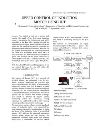
  • 1. 1 Abstract-- This project is built up to control and monitor the speed of the three-phase induction motor by introducing the Arduino and node MCU controller as the key roles. Arduino is used for implementing the pulse width modulation (PWM) signal and the speed of the motor is controlled by using three-phase and driver circuits. And also, in this project the harmonics and switching losses of the circuit will be reduced. Here, Node MCU is used to increase and decrease the induction motor’s speed. The feedback of the speed connection is established to Node MCU controller and thus, the Node MCU transfer the speed signal through Wi- Fi. With the help of IP address and logging into it, we can control the speed by our self within the permissible bandwidth of Wi-Fi. I. INTRODUCTION The Internet of Things (IOT) is a network of physical objects are embedded with devices, sensor, network connectivity are provided with unique identifiers and the ability to automatically collect and transfer data over a network without requiring human-to-human or human-to-computer interaction. IOT has evolved from the convergence of wireless technologies, micro-electro mechanical systems and the Internet. The internet of things also called an Internet of objects. Online monitoring system for continuous casting equipment is established based on IOT sensing technology and communication technology. The parameters such as voltage, current, speed and torque of induction motor were monitored. So, input values or parameters are maintained in limits and speed of the induction motor in a controlled manner. IOT achieves the Industrial automation through remote access and also increases the operational efficiency, lower costs, and improve productivity in automation. The various control methods are: Field control method, Armature control method, Ward-Leonard method. And the new trend of controlling leading to the IOT based The benefits by adopting IOT are highly automated, improves efficiency, reduce the manual work and can be operated from various place and Easy to access. II. BLOCK DIAGRAM SYSTEM HARDWARE COMPONENTS 1) Power supply 2) Step down transformer 3) Rectifier and Filter 4) Three Phase Inverter Board 5) TLP 250 Driver Board 6) Node MCU Controller 7) Arduino 8) System 9) Connecting wires B. Sai Praneeth1 , B. Rakesh1 , K. Karthik Reddy1 , P. Jyothi Swaroop1 , J. Srinivasa Rao2 UG students1 , Associate professor2 , Department of Electrical and Electronics Engineering, VNR VJIET, JNTU, Hyderabad, India. SPEED CONTROL OF INDUCTION MOTOR USING IOT
  • 2. 2 III. EXPLANATION OF COMPONENTS 1) POWER SUPPLY: A Power supply used to supply the electrical  power to the electric load. This is usually applied to power converter which converts one form of an electrical energy to another form of an energy like mechanical, solar, electrical to solar energy. Depending on its structure, a supply can get energy from an Electrical energy transmission system. Different examples which convert voltages of AC to DC  are mentioned below: 1) Energy storage devices like fuel cells & batteries 2) Electro-mechanical devices or systems like generators  & alternators. 3) From solar energy which is obtained from the sun. 2) TRANSFORMER: Step Down Transformer: When AC is applied to the primary winding of the power transformer it can either do stepping down or up based on the value of DC needed. In this circuit the transformer rating of 230v/0-12v is used to perform the operation of step-down where a 230V AC converts into 12V AC across the secondary winding. The top of the transformer to be positive and the bottom negative is caused by altering the one of the inputs. The succeeding alteration will cause the reverse temporarily. 1A current rating of the transformer is used in the project and also, it gives isolation between power supply circuits and the power source.The are used to step down high voltages from 11000v to 220v or 110v and also from 220v or 110v to 10, 12, 20 or 24 volts etc. The induced EMF in the secondary winding is proportional to the number of turns on both the primary and secondary winding's Because, of same magnetic flux lines cut both coils of a transformer. The secondary output voltage will be less than the primary input voltage because the number of turns on the secondary winding is less than the number of turns on the primary winding. This type is called stepdown transformer . 3) RECTIFIERS: A rectifier   is a device which converts alternating  current (AC) to direct current (DC), which flows      in only one direction and this process is known as rectification. Rectifiers are of different types  like vacuum tube diodes, mercury-arc valves,    copper and selenium oxide rectifiers, semiconductor diodes, silicon-    controlled rectifiers and other silicon-based  semiconductor switches. Rectifiers have numerous uses, but are found working as components of DC power  supplies and high-voltage direct current power      transmission systems. In a center tapped full wave rectifier, both positive and negative half cycles are rectified. So, no voltage is wasted at the output. Furthermore, the DC output produced by center tapped half wave rectifier is less smoother than the full wave rectifier output FILTERING UNIT: Filter circuits which are capacitors acts as a surge arrester and always follow the rectifier unit. This is also called as a bypassing capacitor or decoupling capacitor. It is used not used to leave the frequency of the DC to appear at the output but also to ‘short’ the ripple with frequency of 120Hz to ground. A load resistor R1 is connected so that a reference to the ground is maintained. C2R2 is used as a low pass filter, C1R1 is for bypassing ripples i.e. it passes only low frequency signals and bypasses high frequency signals. The load resistor should be 1% to 2.5% of the load. O, 1Ω f: It is for bypassing the high frequency disturbances. 10Ω f/25v: It is for maintaining the stability of the voltage at the load side. 1000Ω f/25v: It is for the reduction of ripples from the pulsating.
  • 3. 3 4) Three Phase Voltage Source Inverters Single-phase VSIs and three phase VSIs covers low-range power and high- range applications respectively. The main purpose of these concepts is to provide a 3-phase voltage source, where the voltage, phase, amplitude of the voltages should always control and also most of the applications require sinusoidal voltage waveforms, arbitrary voltages are also required in some emerging applications like active filters, voltage compensators. A) SINUSOIDAL PULSE WIDTH MODULATION In Power electronics, The Sinusoidal Pulse Width Modulation (SPWM) is a well-known as wave shaping technique for realization, a high frequency triangular carrier signal, V1 is compared with a sinusoidal reference signal V of the desired frequency. Modulation index is the magnitude ratio of the reference signal (Vr,) to that of triangular signal (Vc). B) PULSE WIDTH MODULATION When a PWM signal is given to the gate of a power transistor then it causes the turn on and turns off intervals to change from one PWM period to another PWM period according to the same modulating signal. The frequency of a modulating signal is much lower than the PWM signal. So, the energy and its load of the motor depends mostly on the modulating signal 5) DRIVER CIRCUIT COMPONENTS Below mentioned components are used to amplify and triggering the pulses. They are: 1)OPTOCOUPLER 2) BUFFER IC 3) TRANSISTOR OPTOCOUPLER: Optocouplers normally in a small 6-pin or 8- pin IC package, however are basically a mix of two distinct devices an optical transmitter, typically a gallium arsenide LED and an optical receiver, like a photo-transistor or light- triggered diac. These two are isolated by a transparent barrier which obstructs any electrical flow between the two, however allows the passage of light. The essential thought is appeared in Fig.1, alongside the standard circuit image for an optocoupler. BUFFER IC –CD4050: The CD4050BC hex buffers are monolithic complementary MOS (CMOS) incorporated circuits built with N-and P-channel enhancement-mode transistors. These devices high light logic level conversion utilizing just a single supply voltage (VDD). The input signal high level (VIH) can exceeds the VDD supply voltage when these devices are utilized for logic level conversions. These devices are planned for use as hex buffers, CMOS to DTL/TTL converters 6) Node MCU: Node MCU is an opensource IoT platform,    which includes firmware which keeps running    on the ESP8266 Wi-Fi SoC from Espress if          Systems, and equipment which depends on the ESP12 module. The term Node MCU naturally  relates to the firmware instead of the development kits. The firmware utilizes the Lua scripting language which is based on    the eLua project, and based on the Espress if Non-OS SDK for ESP8266. It utilizes many open source ventures, for example, lua- cjson and SPIFFS.    7) ARDUINO/EMBEDDEDSYSTEMS
  • 4. 4 An embedded system is a special-purpose computer system designed to perform one or a few dedicated functions, often with real-time computing constraints. It is usually embedded as part of a complete device including hardware and mechanical parts. In contrast, a general-purpose computer, such as a personal computer, can do many different tasks depending on programming. Embedded systems have become very important today as they control many of the common devices we use. 7) SYSTEM: A PC framework enables clients to enter, control and store information. PC frameworks normally incorporate a PC, screen, console, mouse and other optional components. Yes, you need a PC to program Arduino. once programmed, it will run without the PC. The Arduino isn't powerful enough to run software. You would normally connect it via the network / internet to a server to process data 8) CONNECTING WIRES: connecting wires enables an electrical current to go from one point on a circuit then onto the next that because power needs a medium through which it can move. The vast majority of the connecting wires are comprised of copper or aluminum. Copper is cheap and great conductivity. Rather than the copper, we can likewise utilize silver which has high conductivity however it is too costly to even think about using. CONNECTION BETWEEN ARDUINO- DRIVER CIRCUIT - NODE MCU III. MATLAB SIMULATION FOR 3-PHASE VOLTAGE SOURCE INVERTER (180 DEGRESS CONDUCTION MODE) IV. HARDWARE IMPLEMENTATION MATLAB/ SIMULATION RESULT:
  • 5. 5 HARWARE RESULT : V. CONCLUSION This project results the design and implementation of Internet of things for control the function of the 3-phase motor using technique of wireless communication. The major idea is long-distance connectivity between location of the machine and user and also to provide flexible. The major advantages of the developed system are to have a continuous monitoring over industrial applications and also providing e for agricultural application which control the induction motor. This work is mainly focused on the improvement of a reliable smart Industrial monitoring and controlling system. By this efficiency of the system can be further improved. VI. REFERENCES [1] “remote controlling and monitoring of induction motors using internet”, abdulkadir, cakır, hakan cali’s, gokhan turan suleiman demirel university, faculty of technology, department of electrical and electronic engineering, isparta turkey(2014). [2] “Real-Time Monitoring and Control of the Parameters of an Induction Motor", Department Of Electrical and Electronics Engineering, Technology of Faculty, Gazi UniversityTeknikokullar Ankara, Turkey . [3] Woodford, “induction motors”, [online]. Available: http://www.explainthatstuff.com/induction- motors.html. [accessed: 4- november- 2015]. [4] “Research on remote wireless monitoring system based on GPRS and MCU” , Zhong- Xuan, J. Xiau-Yu, H. Zhao-Fu, Z. Yan-Tao, D. Meng,Int. Conf. Computational Problem Solving ICCP 2010, Lijiang, China, Dec. [5]. J. S. Hsu and A. M. A. Amin, “Torque calculations of current-source Induction machines using the 1-2-0 coordinate system,” IEEE Trans. Ind.Electron. vol. 37, no. 1, pp. 34– 40, Feb. 1990. [6]. Shamsul Aizam Zulkifli, Mohd Najib Hussin, Abdul Salam Saad “MATLAB Arduino as a Low Cost Microcontroller for 3 phase inverter” 978-1- 4799-6428- 4/14/$31.00 ©2014 IEEE. [7] S.-J. Park, F.-S. Kang, M. H. Lee, and C.-U. Kim, “A new single-phase five-level PWM inverter employing a deadbeat control scheme,” IEEE Trans. Power Electron., vol. 18, no. 3, pp. 831–843, May 2003. [8] Y. Hinago and H. Koizumi, “A switched- capacitor inverter using series/ parallel conversion with inductive load,” IEEE Trans. Ind. Electron., vol. 59, no. 2, pp. 878–887, Feb. 2012.
  • 6. 6
  • 7. 6