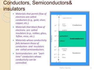
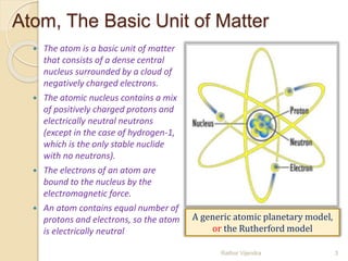
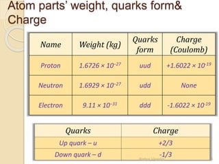
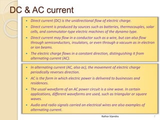
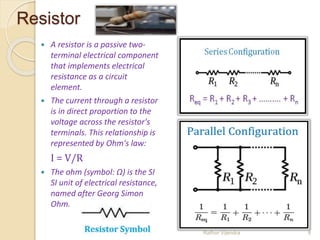
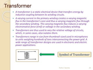
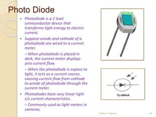
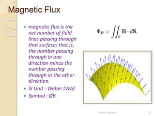
VGEC EC (I) Presents
Basic Electronics Vocabulary
Rathor Vijendra 1
Conductors, Semiconductors&
insulators
 Materials that permit flow of
electrons are called
conductors (e.g., gold, silver,
copper, etc.).
 Materials that block flow of
electrons are called
insulators (e.g., rubber, glass,
Teflon, mica, etc.).
 Materials whose conductivity
falls between those of
conductors and insulators
are called semiconductors.
 Semiconductors are “part-
time” conductors whose
conductivity can be
controlled.
Rathor Vijendra 2
Atom, The Basic Unit of Matter
 The atom is a basic unit of matter
that consists of a dense central
nucleus surrounded by a cloud of
negatively charged electrons.
 The atomic nucleus contains a mix
of positively charged protons and
electrically neutral neutrons
(except in the case of hydrogen-1,
which is the only stable nuclide
with no neutrons).
 The electrons of an atom are
bound to the nucleus by the
electromagnetic force.
 An atom contains equal number of
protons and electrons, so the atom
is electrically neutral
Rathor Vijendra 3
A generic atomic planetary model,
or the Rutherford model
Atom parts’ weight, quarks form&
Charge
Name Weight (kg)
Quarks
form
Charge
(Coulomb)
Proton 1.6726 × 10⁻²⁷ uud +1.6022 × 10⁻¹⁹
Neutron 1.6929 × 10⁻²⁷ udd None
Electron 9.11 × 10⁻³¹ ddd -1.6022 × 10⁻¹⁹
Quarks Charge
Up quark – u +2/3
Down quark – d -1/3Rathor Vijendra 4
Voltage, electrical potential
difference, or an electric tension
 Voltage is the electric potential
difference between two points, or
the difference in electric potential
energy of a unit test charge
transported between two points.
 Voltage is equal to the work done
per unit charge against a static
electric field to move the charge
between two points.
 A voltmeter can be used to measure
the voltage (or potential difference)
between two points in a system.
 Units of Voltage :
1. joules per coulomb
2. volt (SI Unit)
Rathor Vijendra 5
Batteries are sources of voltage
in many electric circuits
Common symbol(s):
V , ΔV , E
Electric current
 An electric current is a flow of
electric charge. Electric
charge flows when there is
voltage present across a
conductor.
 In electric circuits this charge
is often carried by moving
electrons in a wire. It can also
be carried by ions in an
electrolyte, or by both ions
and electrons such as in a
plasma.
 The direction of conventional
current is defined arbitrarily
to be the direction of the flow
of positive charges.
 SI Unit : Ampere (C/s)
Rathor Vijendra 6
The symbol for a battery in a
circuit diagram.
DC & AC current
 Direct current (DC) is the unidirectional flow of electric charge.
 Direct current is produced by sources such as batteries, thermocouples, solar
cells, and commutator-type electric machines of the dynamo type.
 Direct current may flow in a conductor such as a wire, but can also flow
through semiconductors, insulators, or even through a vacuum as in electron
or ion beams.
 The electric charge flows in a constant direction, distinguishing it from
alternating current (AC).
 In alternating current (AC, also ac), the movement of electric charge
periodically reverses direction.
 AC is the form in which electric power is delivered to businesses and
residences.
 The usual waveform of an AC power circuit is a sine wave. In certain
applications, different waveforms are used, such as triangular or square
waves.
 Audio and radio signals carried on electrical wires are also examples of
alternating current.
Rathor Vijendra 7
Resistor
 A resistor is a passive two-
terminal electrical component
that implements electrical
resistance as a circuit
element.
 The current through a resistor
is in direct proportion to the
voltage across the resistor's
terminals. This relationship is
represented by Ohm's law:
I = V/R
 The ohm (symbol: Ω) is the SI
SI unit of electrical resistance,
named after Georg Simon
Ohm.
Rathor Vijendra 8
Color code for Resistances
Rathor Vijendra 9
Resistivity and conductivity
 Electrical resistivity (also
known as resistivity, specific
electrical resistance, or
volume resistivity) quantifies
how strongly a given material
opposes the flow of electric
current.
 Resistivity is commonly
represented by the Greek
letter ρ (rho).
 SI unit : ohm⋅ metre (Ω⋅m)
 Electrical conductivity or specific
conductance is the reciprocal of
electrical resistivity, and
measures a material's ability to
conduct an electric current.
 It is commonly represented by the
Greek letter σ(sigma), but
κ(kappa) (especially in electrical
engineering) or γ (gamma) are
also occasionally used.
 SI unit : Siemens per meter
(S⋅m−1)
Rathor Vijendra 10
Q factor
 In physics and engineering the
quality factor or Q factor is a
dimensionless parameter that
describes how under-damped an
oscillator or resonator is, or
equivalently, characterizes a
resonator's bandwidth relative to its
center frequency.
 Higher Q indicates a lower rate of
energy loss relative to the stored
energy of the resonator; the
oscillations die out more slowly. A
pendulum suspended from a high-
quality bearing, oscillating in air, has
a high Q, while a pendulum
immersed in oil has a low one.
Resonators with high quality factors
have low damping so that they ring
longer. Rathor Vijendra 11
N type silicon
 Pentavalent impurities such as phosphorus, arsenic, antimony, and
bismuth have 5 valence electrons.
 When phosphorus impurity is added to Si, every phosphorus atom’s four
valence electrons are locked up in covalent bond with valence electrons of
four neighboring Si atoms. However, the 5th valence electron of
phosphorus atom does not find a binding electron and thus remains free
to float. When a voltage is applied across the silicon-phosphorus mixture,
free electrons migrate toward the positive voltage end.
 When phosphorus is added to Si to yield the above effect, we say that Si is
doped with phosphorus. The resulting mixture is called N-type silicon (N:
negative charge carrier silicon).
 The Pentavalent impurities are referred to as donor impurities.
Rathor Vijendra 12
P type silicon
 Trivalent impurities e.g., boron, aluminum, indium, and gallium have 3
valence electrons.
 When boron is added to Si, every boron atom’s three valence electrons are
locked up in covalent bond with valence electrons of three neighboring Si
atoms. However, a vacant spot “hole” is created within the covalent bond
between one boron atom and a neighboring Si atom. The holes are
considered to be positive charge carriers. When a voltage is applied across
the silicon-boron mixture, a hole moves toward the negative voltage end
while a neighboring electron fills in its place.
 When boron is added to Si to yield the above effect, we say that Si is doped
with boron. The resulting mixture is called P-type silicon (P: positive charge
carrier silicon).
 The trivalent impurities are referred to as acceptor impurities.
Rathor Vijendra 13
Diode
 A diode is a 2 lead semiconductor that acts as
a one way gate to electron flow.
 Diode allows current to pass in only one
direction.
 A pn-junction diode is formed by joining
together n-type and p-type silicon.
 The p-side is called anode and the n-side is
called cathode.
Rathor Vijendra 14
Forward Bias & Reverse Bias
 When the anode and cathode of a pn-junction diode are
connected to external voltage such that the potential at
anode is higher than the potential at cathode, the diode is
said to be forward biased.
 In a forward-biased diode current is allowed to flow through
the device.
 When potential at anode is smaller than the potential at
cathode, the diode is said to be reverse biased.
 In a reverse-biased diode current is blocked.
Rathor Vijendra 15
Rectifier: half wave and full wave
 A rectifier is an electrical device that converts alternating current (AC),
which periodically reverses direction, to direct current (DC), which
flows in only one direction.
Rathor Vijendra 16
Full-wave rectifier Circuit
Half-wave rectifier Circuit
Transistor
 A three lead semiconductor device that acts as:
– an electrically controlled switch, or
– a current amplifier.
 Transistor is analogous to a faucet.
– Turning faucet’s control knob alters the flow rate of water
coming out from the faucet.
– A small voltage/current applied at transistor’s control lead
controls a larger current flow through its other two leads.
Rathor Vijendra 17
Capacitor
 Next to resistors, capacitors
are probably the second most
commonly used component in
electronic circuits.
 A capacitor is a device that
can temporarily store an
electric charge.
 Capacitors come in several
different varieties, the two
most common being ceramic
disk and electrolytic.
 SI Unit : Farad (F)
 Capacitance : C=Q/V
Rathor Vijendra 18
Ceramic Capacitor
Capacitor
 The amount of capacitance of
a given capacitor is usually
measured in microfarads,
abbreviated μF.
 When capacitor is put in
parallel the over all
capacitance C is
C=C1 +C2 +C3 +C4+…
 and in series the over all
capacitance C is
Rathor Vijendra 19
Transformer
 A transformer is a static electrical device that transfers energy by
inductive coupling between its winding circuits.
 A varying current in the primary winding creates a varying magnetic
flux in the transformer's core and thus a varying magnetic flux through
the secondary winding. This varying magnetic flux induces a varying
electromotive force (emf) or voltage in the secondary winding.
 Transformers are thus used to vary the relative voltage of circuits,
which, in some cases, also isolates them.
 Transformers range in size from thumbnail-sized used in microphones
to units weighing hundreds of tons interconnecting the power grid. A
wide range of transformer designs are used in electronic and electric
power applications.
Rathor Vijendra 20
Symbol of Transformer
Transformer
Rathor Vijendra 21
The value of the ratio a being
respectively higher and lower than unity
for step-down and step-up transformers.
Inductor
 An inductor, also called a coil or
reactor, is a passive two-terminal
electrical component which
resists changes in electric current
passing through it.
 It consists of a conductor such as
a wire, usually wound into a coil.
 When a current flows through it,
energy is stored temporarily in a
magnetic field in the coil.
 When the current flowing
through an inductor changes, the
time-varying magnetic field
induces a voltage in the
conductor, according to Faraday’s
law of electromagnetic induction,
which opposes the change in
current that created it.
 SI Unit of inductance : Henry (H)
Rathor Vijendra 22
LED
 2 lead semiconductor device.
 Light emitting PN-junction diode.
– Visible or infrared light.
 Has polarity.
 Recall diodes act as a one way
gate to current flow.
– A forward-biased PN-junction
diode allows current flow from
anode to cathode.
 An LED conducts and emits light
when its anode is made more
positive (approx. 1.4V) than its
cathode.
– With reverse polarity, LED
stops conducting and emitting
light.
Rathor Vijendra 23
Photo Diode
 Photodiode is a 2 lead
semiconductor device that
transforms light energy to electric
current.
 Suppose anode and cathode of a
photodiode are wired to a current
meter.
– When photodiode is placed in
dark, the current meter displays
zero current flow.
– When the photodiode is expose to
light, it acts as a current source,
causing current flow from cathode
to anode of photodiode through the
current meter.
 Photodiodes have very linear light
v/s current characteristics.
– Commonly used as light meters in
cameras.
Rathor Vijendra 24
Solar cell
 Solar cells are photodiodes with
very large surface areas.
 Compared to usual
photodiodes, the large surface
area in photodiode of a solar
cell yields
– a device that is more sensitive
to incoming light.
– a device that yields more
power (larger current/volts).
 Solar cells yield more power.
 A single solar cell may provide
up to 0.5V that can supply 0.1A
when exposed to bright light.
Rathor Vijendra 25
Switch
 a switch is an electrical
component that can break
an electrical circuit, interrupting
the current or diverting it from one
conductor to another
 The most familiar form of switch is a
manually
operated electromechanical device
with one or more sets of electrical
contacts, which are connected to
external circuits.
 Each set of contacts can be in one of
two states: either "closed" meaning
the contacts are touching and
electricity can flow between them, or
"open", meaning the contacts are
separated and the switch is no
conducting.
 A relay is an electrically operated
switch Rathor Vijendra 26
Magnetic Flux
 magnetic flux is the
net number of field
lines passing through
that surface; that is,
the number passing
through in one
direction minus the
number passing
through in the other
direction.
 SI Unit : Weber (Wb)
 Symbol : ØB
Rathor Vijendra 27
Lenz’s Law
 Lenz's law is a common
way of understanding
how electromagnetic
circuits obey Newton's
third law and the
conservation of energy.
 An induced electromotive
force (emf) always gives
rise to a current whose
magnetic field opposes
the original change in
magnetic flux.
 Lenz's law is shown
with the negative sign
in Faraday's law of
induction
Rathor Vijendra 28
• which indicates that the
induced emf and the
change in magnetic flux
have opposite signs.
Logic Gates
 A logic gate is an idealized or physical device
implementing a Boolean function, that is, it performs a
logical operation on one or more logical inputs, and
produces a single logical output.
 Logic gates are primarily implemented using diodes or
transistors acting as electronic switches, but can also be
constructed using electromagnetic relays (relay logic),
fluidic logic, pneumatic logic, optics, molecules, or even
mechanical elements.
Rathor Vijendra 29
Boolean equations

Rathor Vijendra 30
Boolean equations
Rathor Vijendra 31
Boolean equations

Rathor Vijendra 32
Thank You
Rathor Vijendra 33
Created By:
Rathor Vijendrasingh
And Others:
1. Lalit Kumawat
2. Sneh Gandhi
3. Nisarg Thakar
4. Poorn Mehta
Rathor Vijendra 34

Basic electronics vocabulary

  • 1.
    VGEC EC (I)Presents Basic Electronics Vocabulary Rathor Vijendra 1
  • 2.
    Conductors, Semiconductors& insulators  Materialsthat permit flow of electrons are called conductors (e.g., gold, silver, copper, etc.).  Materials that block flow of electrons are called insulators (e.g., rubber, glass, Teflon, mica, etc.).  Materials whose conductivity falls between those of conductors and insulators are called semiconductors.  Semiconductors are “part- time” conductors whose conductivity can be controlled. Rathor Vijendra 2
  • 3.
    Atom, The BasicUnit of Matter  The atom is a basic unit of matter that consists of a dense central nucleus surrounded by a cloud of negatively charged electrons.  The atomic nucleus contains a mix of positively charged protons and electrically neutral neutrons (except in the case of hydrogen-1, which is the only stable nuclide with no neutrons).  The electrons of an atom are bound to the nucleus by the electromagnetic force.  An atom contains equal number of protons and electrons, so the atom is electrically neutral Rathor Vijendra 3 A generic atomic planetary model, or the Rutherford model
  • 4.
    Atom parts’ weight,quarks form& Charge Name Weight (kg) Quarks form Charge (Coulomb) Proton 1.6726 × 10⁻²⁷ uud +1.6022 × 10⁻¹⁹ Neutron 1.6929 × 10⁻²⁷ udd None Electron 9.11 × 10⁻³¹ ddd -1.6022 × 10⁻¹⁹ Quarks Charge Up quark – u +2/3 Down quark – d -1/3Rathor Vijendra 4
  • 5.
    Voltage, electrical potential difference,or an electric tension  Voltage is the electric potential difference between two points, or the difference in electric potential energy of a unit test charge transported between two points.  Voltage is equal to the work done per unit charge against a static electric field to move the charge between two points.  A voltmeter can be used to measure the voltage (or potential difference) between two points in a system.  Units of Voltage : 1. joules per coulomb 2. volt (SI Unit) Rathor Vijendra 5 Batteries are sources of voltage in many electric circuits Common symbol(s): V , ΔV , E
  • 6.
    Electric current  Anelectric current is a flow of electric charge. Electric charge flows when there is voltage present across a conductor.  In electric circuits this charge is often carried by moving electrons in a wire. It can also be carried by ions in an electrolyte, or by both ions and electrons such as in a plasma.  The direction of conventional current is defined arbitrarily to be the direction of the flow of positive charges.  SI Unit : Ampere (C/s) Rathor Vijendra 6 The symbol for a battery in a circuit diagram.
  • 7.
    DC & ACcurrent  Direct current (DC) is the unidirectional flow of electric charge.  Direct current is produced by sources such as batteries, thermocouples, solar cells, and commutator-type electric machines of the dynamo type.  Direct current may flow in a conductor such as a wire, but can also flow through semiconductors, insulators, or even through a vacuum as in electron or ion beams.  The electric charge flows in a constant direction, distinguishing it from alternating current (AC).  In alternating current (AC, also ac), the movement of electric charge periodically reverses direction.  AC is the form in which electric power is delivered to businesses and residences.  The usual waveform of an AC power circuit is a sine wave. In certain applications, different waveforms are used, such as triangular or square waves.  Audio and radio signals carried on electrical wires are also examples of alternating current. Rathor Vijendra 7
  • 8.
    Resistor  A resistoris a passive two- terminal electrical component that implements electrical resistance as a circuit element.  The current through a resistor is in direct proportion to the voltage across the resistor's terminals. This relationship is represented by Ohm's law: I = V/R  The ohm (symbol: Ω) is the SI SI unit of electrical resistance, named after Georg Simon Ohm. Rathor Vijendra 8
  • 9.
    Color code forResistances Rathor Vijendra 9
  • 10.
    Resistivity and conductivity Electrical resistivity (also known as resistivity, specific electrical resistance, or volume resistivity) quantifies how strongly a given material opposes the flow of electric current.  Resistivity is commonly represented by the Greek letter ρ (rho).  SI unit : ohm⋅ metre (Ω⋅m)  Electrical conductivity or specific conductance is the reciprocal of electrical resistivity, and measures a material's ability to conduct an electric current.  It is commonly represented by the Greek letter σ(sigma), but κ(kappa) (especially in electrical engineering) or γ (gamma) are also occasionally used.  SI unit : Siemens per meter (S⋅m−1) Rathor Vijendra 10
  • 11.
    Q factor  Inphysics and engineering the quality factor or Q factor is a dimensionless parameter that describes how under-damped an oscillator or resonator is, or equivalently, characterizes a resonator's bandwidth relative to its center frequency.  Higher Q indicates a lower rate of energy loss relative to the stored energy of the resonator; the oscillations die out more slowly. A pendulum suspended from a high- quality bearing, oscillating in air, has a high Q, while a pendulum immersed in oil has a low one. Resonators with high quality factors have low damping so that they ring longer. Rathor Vijendra 11
  • 12.
    N type silicon Pentavalent impurities such as phosphorus, arsenic, antimony, and bismuth have 5 valence electrons.  When phosphorus impurity is added to Si, every phosphorus atom’s four valence electrons are locked up in covalent bond with valence electrons of four neighboring Si atoms. However, the 5th valence electron of phosphorus atom does not find a binding electron and thus remains free to float. When a voltage is applied across the silicon-phosphorus mixture, free electrons migrate toward the positive voltage end.  When phosphorus is added to Si to yield the above effect, we say that Si is doped with phosphorus. The resulting mixture is called N-type silicon (N: negative charge carrier silicon).  The Pentavalent impurities are referred to as donor impurities. Rathor Vijendra 12
  • 13.
    P type silicon Trivalent impurities e.g., boron, aluminum, indium, and gallium have 3 valence electrons.  When boron is added to Si, every boron atom’s three valence electrons are locked up in covalent bond with valence electrons of three neighboring Si atoms. However, a vacant spot “hole” is created within the covalent bond between one boron atom and a neighboring Si atom. The holes are considered to be positive charge carriers. When a voltage is applied across the silicon-boron mixture, a hole moves toward the negative voltage end while a neighboring electron fills in its place.  When boron is added to Si to yield the above effect, we say that Si is doped with boron. The resulting mixture is called P-type silicon (P: positive charge carrier silicon).  The trivalent impurities are referred to as acceptor impurities. Rathor Vijendra 13
  • 14.
    Diode  A diodeis a 2 lead semiconductor that acts as a one way gate to electron flow.  Diode allows current to pass in only one direction.  A pn-junction diode is formed by joining together n-type and p-type silicon.  The p-side is called anode and the n-side is called cathode. Rathor Vijendra 14
  • 15.
    Forward Bias &Reverse Bias  When the anode and cathode of a pn-junction diode are connected to external voltage such that the potential at anode is higher than the potential at cathode, the diode is said to be forward biased.  In a forward-biased diode current is allowed to flow through the device.  When potential at anode is smaller than the potential at cathode, the diode is said to be reverse biased.  In a reverse-biased diode current is blocked. Rathor Vijendra 15
  • 16.
    Rectifier: half waveand full wave  A rectifier is an electrical device that converts alternating current (AC), which periodically reverses direction, to direct current (DC), which flows in only one direction. Rathor Vijendra 16 Full-wave rectifier Circuit Half-wave rectifier Circuit
  • 17.
    Transistor  A threelead semiconductor device that acts as: – an electrically controlled switch, or – a current amplifier.  Transistor is analogous to a faucet. – Turning faucet’s control knob alters the flow rate of water coming out from the faucet. – A small voltage/current applied at transistor’s control lead controls a larger current flow through its other two leads. Rathor Vijendra 17
  • 18.
    Capacitor  Next toresistors, capacitors are probably the second most commonly used component in electronic circuits.  A capacitor is a device that can temporarily store an electric charge.  Capacitors come in several different varieties, the two most common being ceramic disk and electrolytic.  SI Unit : Farad (F)  Capacitance : C=Q/V Rathor Vijendra 18 Ceramic Capacitor
  • 19.
    Capacitor  The amountof capacitance of a given capacitor is usually measured in microfarads, abbreviated μF.  When capacitor is put in parallel the over all capacitance C is C=C1 +C2 +C3 +C4+…  and in series the over all capacitance C is Rathor Vijendra 19
  • 20.
    Transformer  A transformeris a static electrical device that transfers energy by inductive coupling between its winding circuits.  A varying current in the primary winding creates a varying magnetic flux in the transformer's core and thus a varying magnetic flux through the secondary winding. This varying magnetic flux induces a varying electromotive force (emf) or voltage in the secondary winding.  Transformers are thus used to vary the relative voltage of circuits, which, in some cases, also isolates them.  Transformers range in size from thumbnail-sized used in microphones to units weighing hundreds of tons interconnecting the power grid. A wide range of transformer designs are used in electronic and electric power applications. Rathor Vijendra 20 Symbol of Transformer
  • 21.
    Transformer Rathor Vijendra 21 Thevalue of the ratio a being respectively higher and lower than unity for step-down and step-up transformers.
  • 22.
    Inductor  An inductor,also called a coil or reactor, is a passive two-terminal electrical component which resists changes in electric current passing through it.  It consists of a conductor such as a wire, usually wound into a coil.  When a current flows through it, energy is stored temporarily in a magnetic field in the coil.  When the current flowing through an inductor changes, the time-varying magnetic field induces a voltage in the conductor, according to Faraday’s law of electromagnetic induction, which opposes the change in current that created it.  SI Unit of inductance : Henry (H) Rathor Vijendra 22
  • 23.
    LED  2 leadsemiconductor device.  Light emitting PN-junction diode. – Visible or infrared light.  Has polarity.  Recall diodes act as a one way gate to current flow. – A forward-biased PN-junction diode allows current flow from anode to cathode.  An LED conducts and emits light when its anode is made more positive (approx. 1.4V) than its cathode. – With reverse polarity, LED stops conducting and emitting light. Rathor Vijendra 23
  • 24.
    Photo Diode  Photodiodeis a 2 lead semiconductor device that transforms light energy to electric current.  Suppose anode and cathode of a photodiode are wired to a current meter. – When photodiode is placed in dark, the current meter displays zero current flow. – When the photodiode is expose to light, it acts as a current source, causing current flow from cathode to anode of photodiode through the current meter.  Photodiodes have very linear light v/s current characteristics. – Commonly used as light meters in cameras. Rathor Vijendra 24
  • 25.
    Solar cell  Solarcells are photodiodes with very large surface areas.  Compared to usual photodiodes, the large surface area in photodiode of a solar cell yields – a device that is more sensitive to incoming light. – a device that yields more power (larger current/volts).  Solar cells yield more power.  A single solar cell may provide up to 0.5V that can supply 0.1A when exposed to bright light. Rathor Vijendra 25
  • 26.
    Switch  a switchis an electrical component that can break an electrical circuit, interrupting the current or diverting it from one conductor to another  The most familiar form of switch is a manually operated electromechanical device with one or more sets of electrical contacts, which are connected to external circuits.  Each set of contacts can be in one of two states: either "closed" meaning the contacts are touching and electricity can flow between them, or "open", meaning the contacts are separated and the switch is no conducting.  A relay is an electrically operated switch Rathor Vijendra 26
  • 27.
    Magnetic Flux  magneticflux is the net number of field lines passing through that surface; that is, the number passing through in one direction minus the number passing through in the other direction.  SI Unit : Weber (Wb)  Symbol : ØB Rathor Vijendra 27
  • 28.
    Lenz’s Law  Lenz'slaw is a common way of understanding how electromagnetic circuits obey Newton's third law and the conservation of energy.  An induced electromotive force (emf) always gives rise to a current whose magnetic field opposes the original change in magnetic flux.  Lenz's law is shown with the negative sign in Faraday's law of induction Rathor Vijendra 28 • which indicates that the induced emf and the change in magnetic flux have opposite signs.
  • 29.
    Logic Gates  Alogic gate is an idealized or physical device implementing a Boolean function, that is, it performs a logical operation on one or more logical inputs, and produces a single logical output.  Logic gates are primarily implemented using diodes or transistors acting as electronic switches, but can also be constructed using electromagnetic relays (relay logic), fluidic logic, pneumatic logic, optics, molecules, or even mechanical elements. Rathor Vijendra 29
  • 30.
  • 31.
  • 32.
  • 33.
  • 34.
    Created By: Rathor Vijendrasingh AndOthers: 1. Lalit Kumawat 2. Sneh Gandhi 3. Nisarg Thakar 4. Poorn Mehta Rathor Vijendra 34