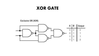
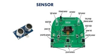
Electronics is the branch of physics concerned with the design of circuits using transistors and microchips to control the behavior and movement of electrons. Key components include resistors, capacitors, inductors, diodes, and transistors. Together, these components can be used to build logic gates which are the basic building blocks of digital circuits and computers. Sensors are also important electronic components that detect changes in the environment and convert them to electrical signals.


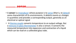
![A good sensor obeys the following rules
Is sensitive to the measured property
Is insensitive to any other property likely to be encountered in its
application
Does not influence the measured property
The sensitivity is then defined as the ratio between output signal and
measured property. For example, if a sensor measures temperature
and has a voltage output, the sensitivity is a constant with the unit
[V/K]; this sensor is linear because the ratio is constant at all points of
measurement.
For an analog sensor signal to be processed, or used in digital
equipment, it needs to be converted to a digital signal, using
an analog-to-digital converter](https://image.slidesharecdn.com/basicelectronics-150825131734-lva1-app6892/85/Basic-electronics-rtf-78-320.jpg)