Downloaded 19 times
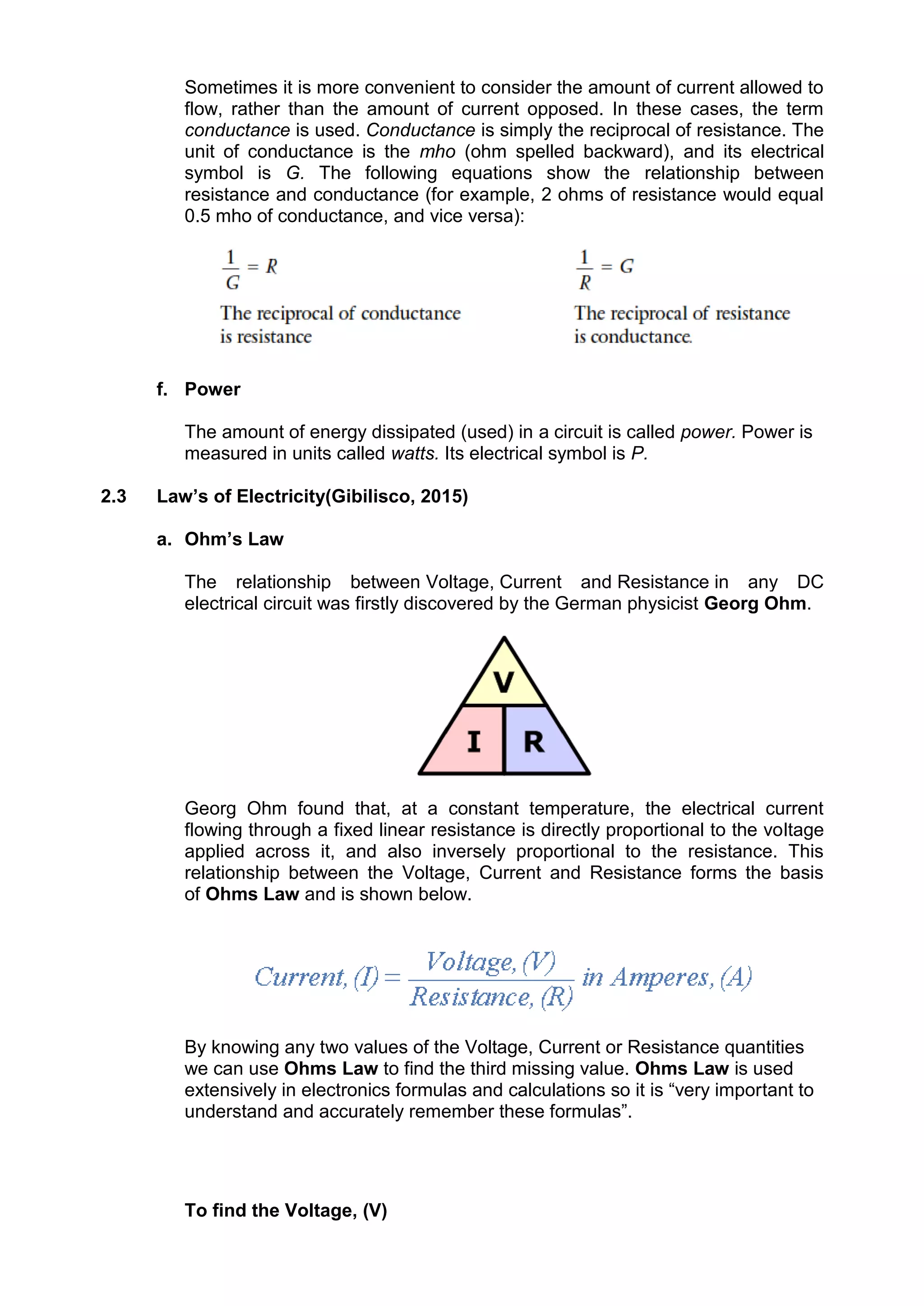
![[ V = I x R] V (volts) = I (amps) x R (Ω)
To find the Current, (I)
[ I = V ÷ R] I (amps) = V (volts) ÷ R (Ω)
To find the Resistance, (R)
[ R = V ÷ I] R (Ω) = V (volts) ÷ I (amps)
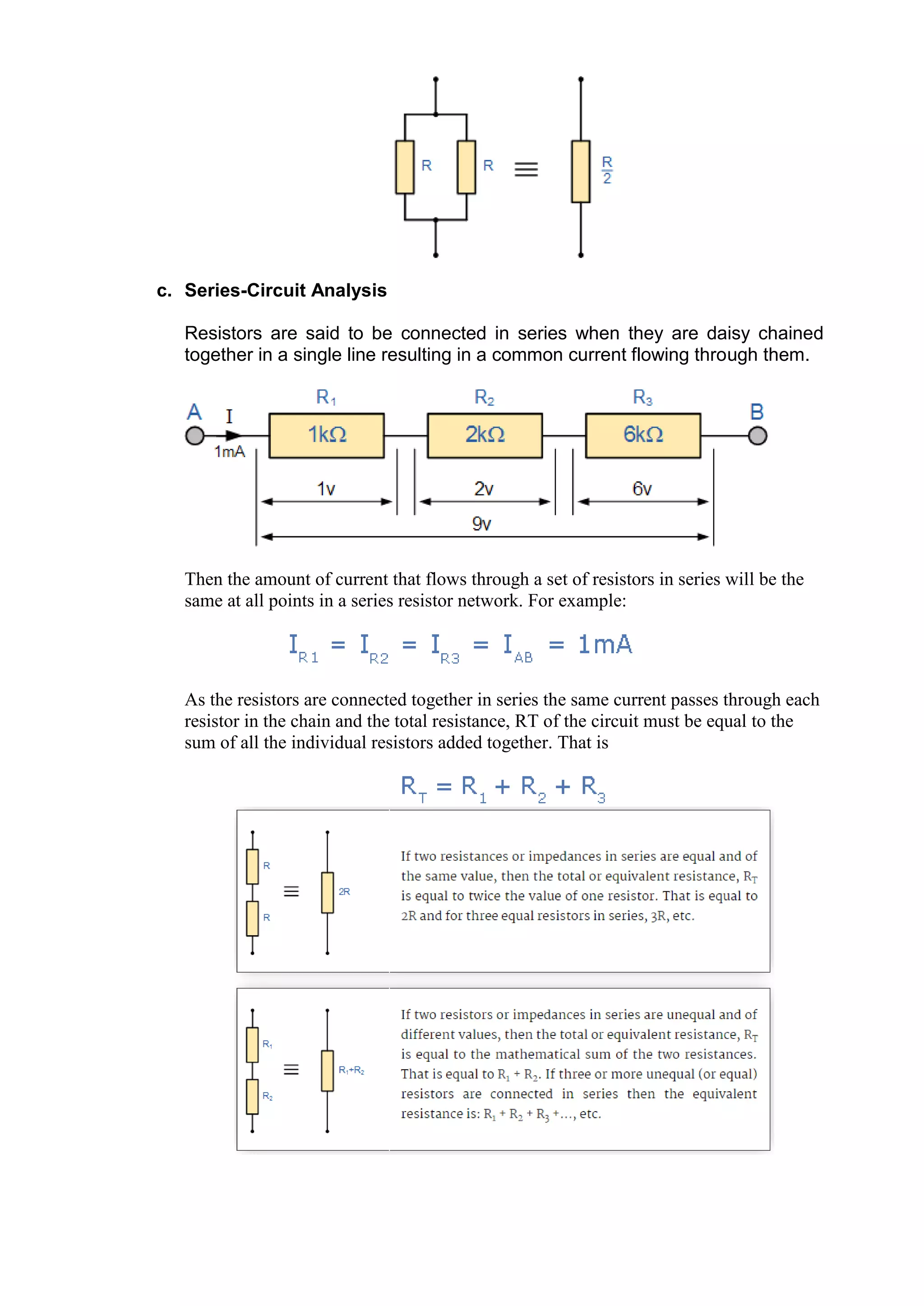
b. Parallel-Circuit Analysis
Resistors are said to be connected together in “Parallel” when both of their
terminals are respectively connected to each terminal of the other resistor or
resistors.
Therefore, for a parallel resistor network this is given as:
Parallel Resistor Equation](https://image.slidesharecdn.com/basicelectronicsforengineerstutorial-170504080026/75/Basic-Electronics-for-Engineers-Tutorial-14-2048.jpg)
![e. Power
Electrical Power, ( P ) in a circuit is the rate at which energy is absorbed or
produced within a circuit. A source of energy such as a voltage will produce
or deliver power while the connected load absorbs it. Light bulbs and heaters
for example, absorb electrical power and convert it into either heat, or light, or
both. The higher their value or rating in watts the more electrical power they
are likely to consume.
The quantity symbol for power is P and is the product of voltage multiplied by
the current with the unit of measurement being the Watt ( W ). Prefixes are
used to denote the various multiples or sub-multiples of a watt, such
as: milliwatts (mW = 10-3W) or kilowatts (kW = 103W).
Then by using Ohm’s law and substituting for the values of V, I and R the
formula for electrical power can be found as:
To find the Power (P)
[ P = V x I ] P (watts) = V (volts) x I (amps)
Also,
[ P = V2 ÷ R ] P (watts) = V2 (volts) ÷ R (Ω)
Also,
[ P = I2 x R ] P (watts) = I2 (amps) x R (Ω)
f. Kirchoff’s Current Law:
Kirchhoffs Current Law or KCL, states that the “total current or charge
entering a junction or node is exactly equal to the charge leaving the node as
it has no other place to go except to leave, as no charge is lost within the
node“. In other words the algebraic sum of ALL the currents entering and
leaving a node must be equal to zero,
I(exiting) + I(entering) = 0. This idea by Kirchhoff is commonly known as
the Conservation of Charge.
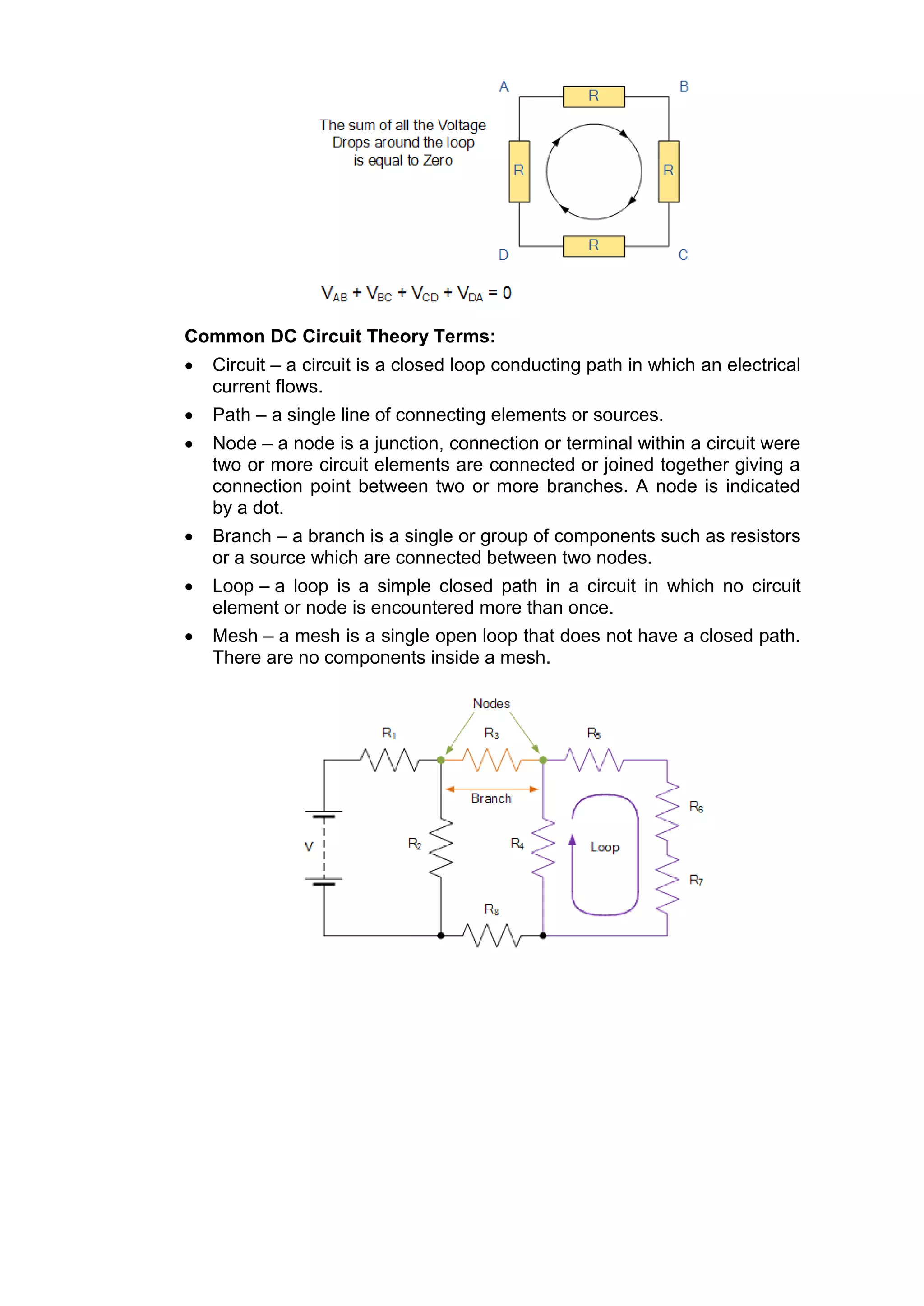
g. Kirchoff’s Voltage Law:
Kirchhoffs Voltage Law or KVL, states that “in any closed loop network, the
total voltage around the loop is equal to the sum of all the voltage drops
within the same loop” which is also equal to zero. In other words the
algebraic sum of all voltages within the loop must be equal to zero. This idea
by Kirchhoff is known as the Conservation of Energy.](https://image.slidesharecdn.com/basicelectronicsforengineerstutorial-170504080026/75/Basic-Electronics-for-Engineers-Tutorial-17-2048.jpg)


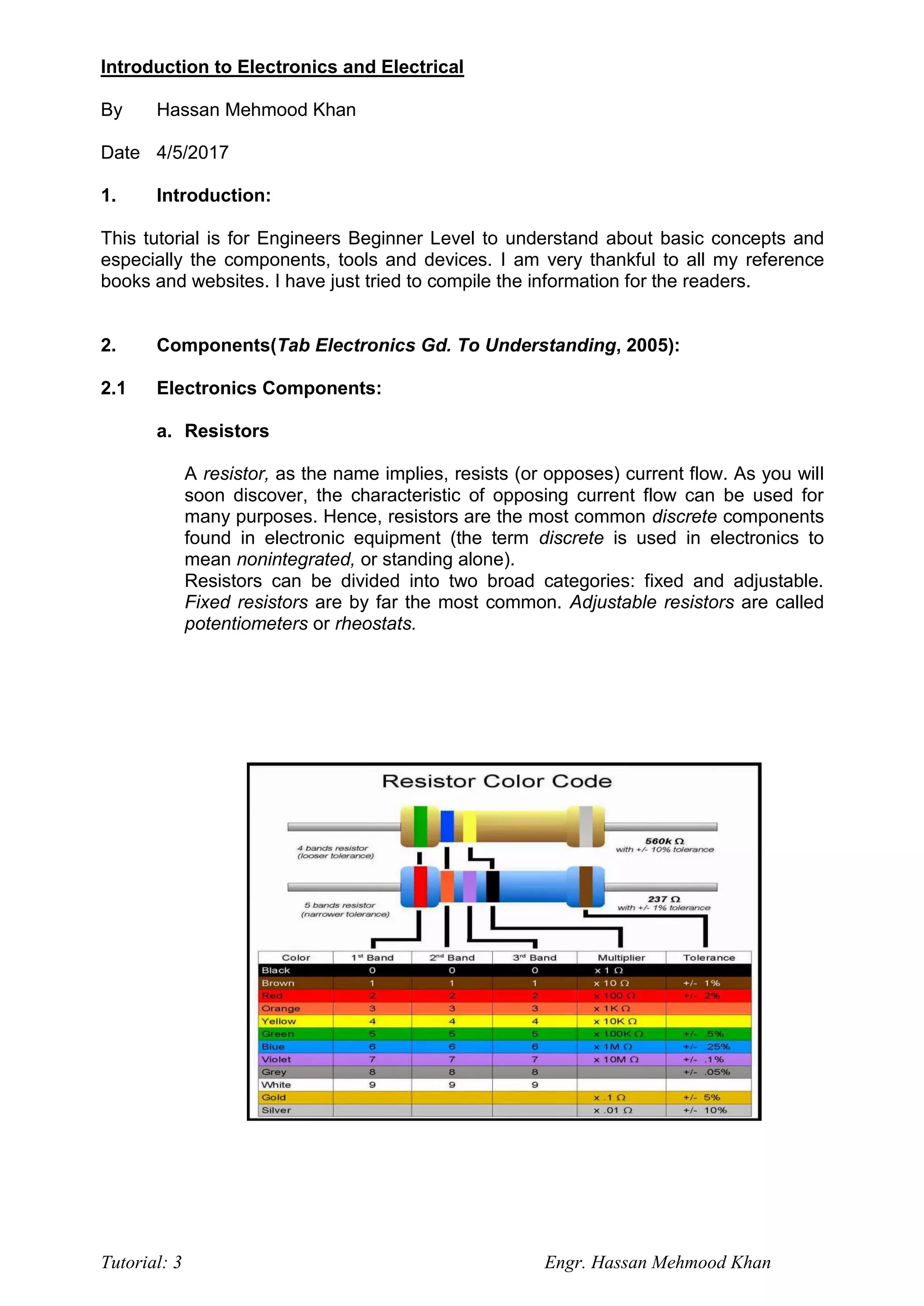
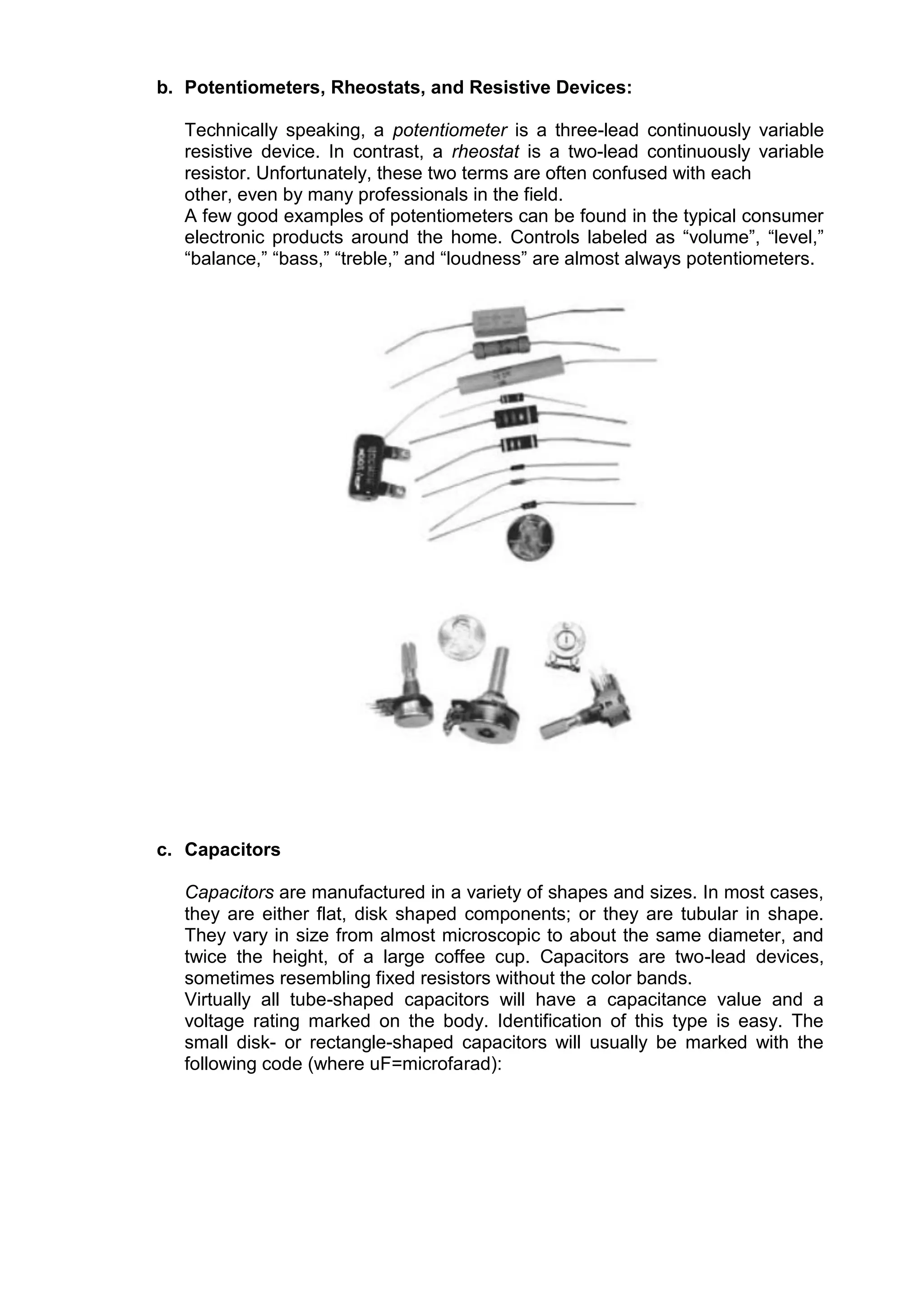
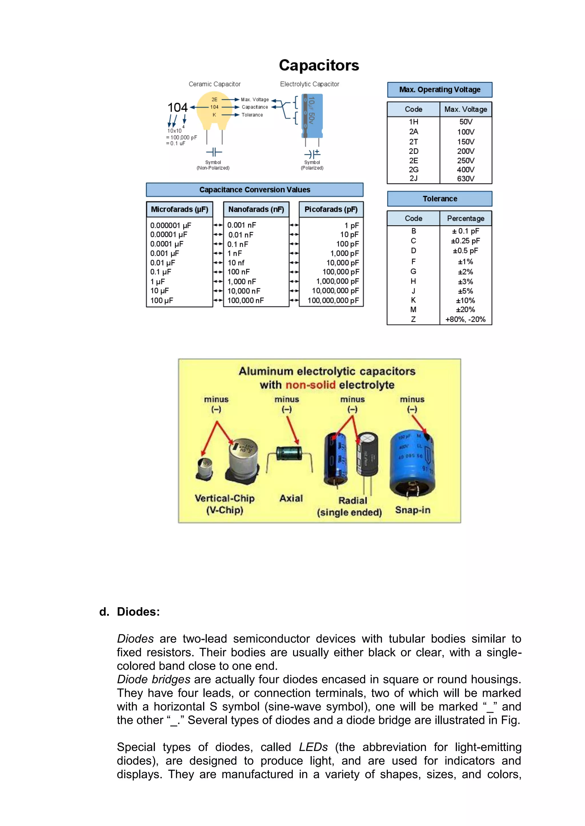
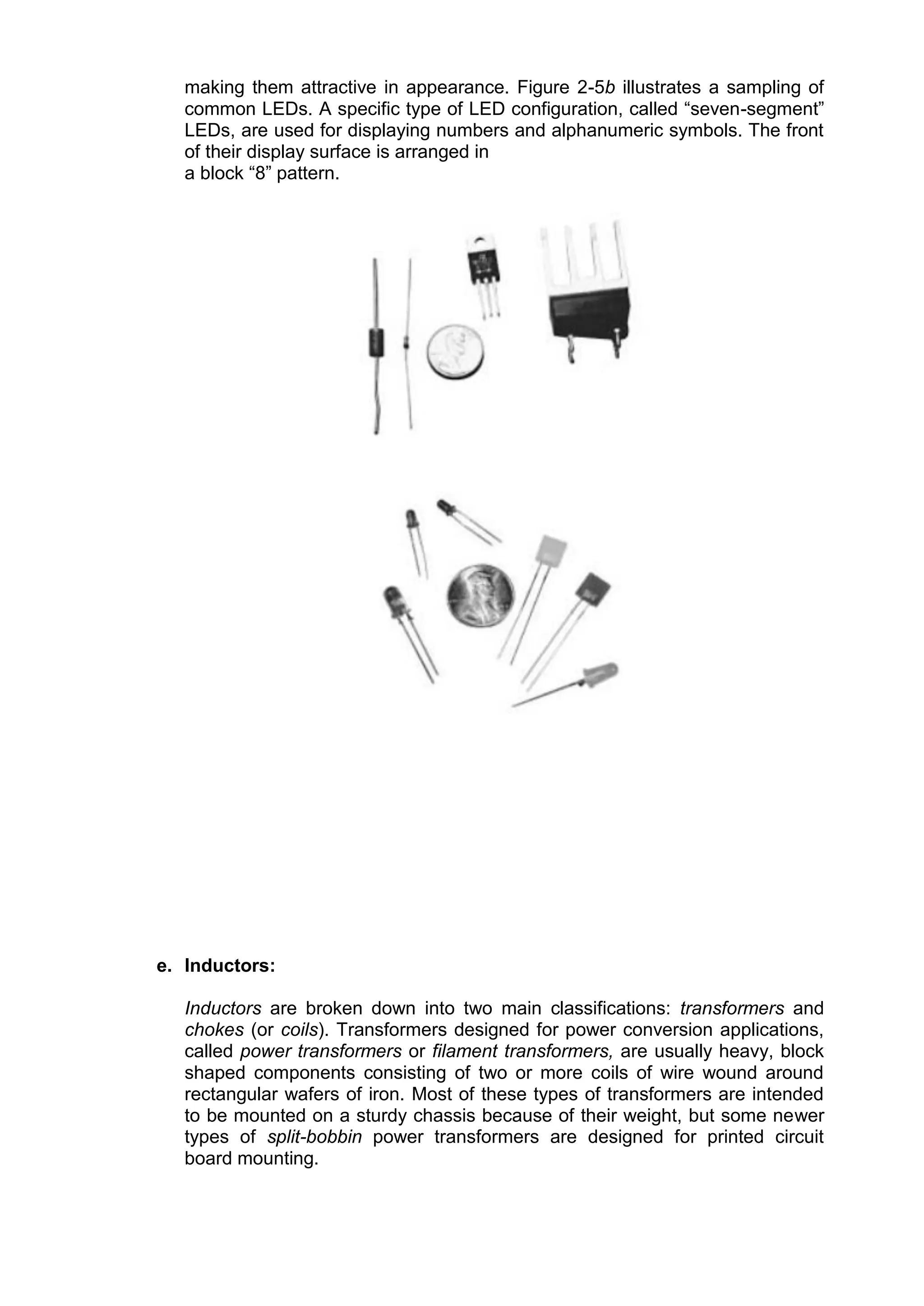
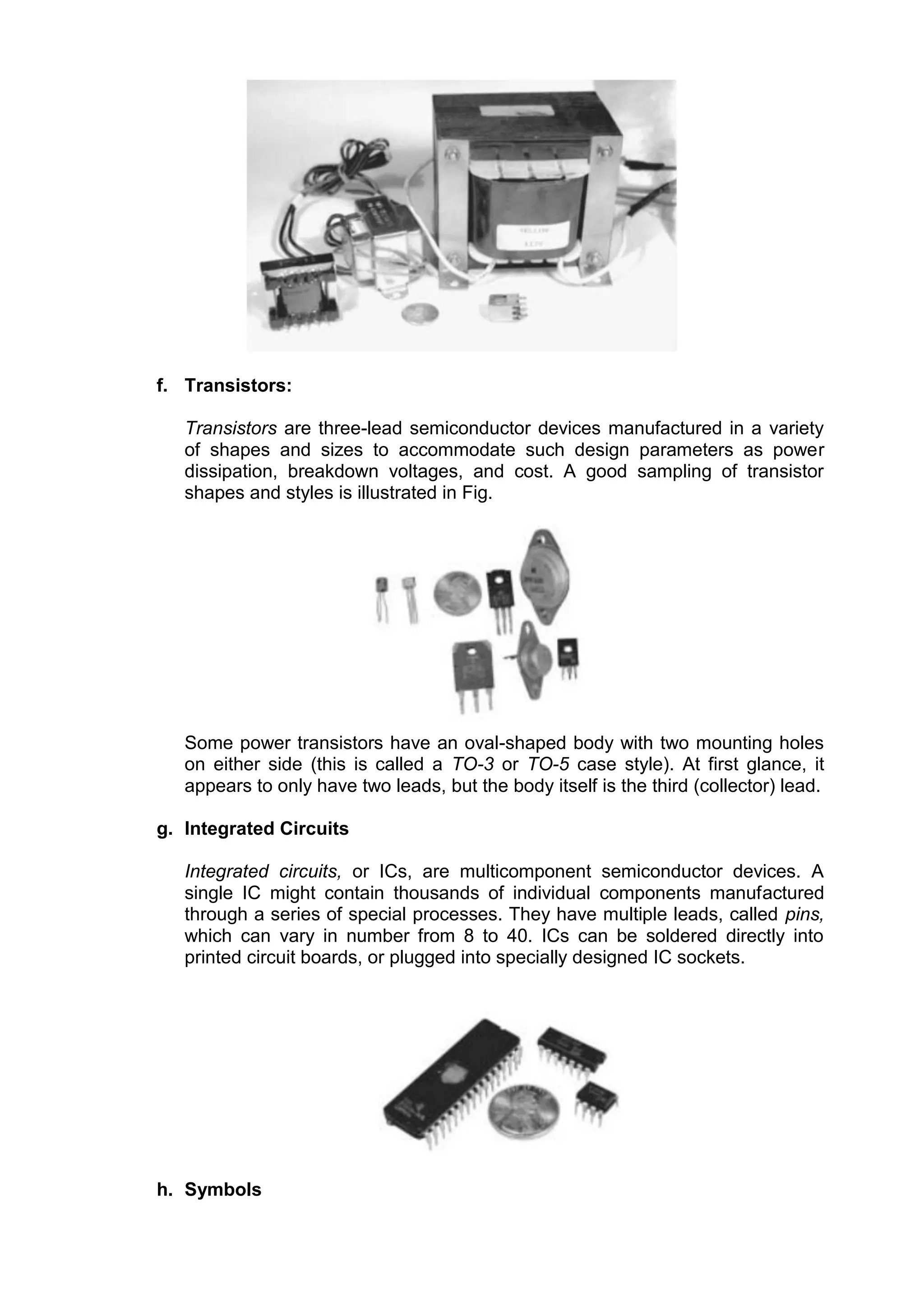
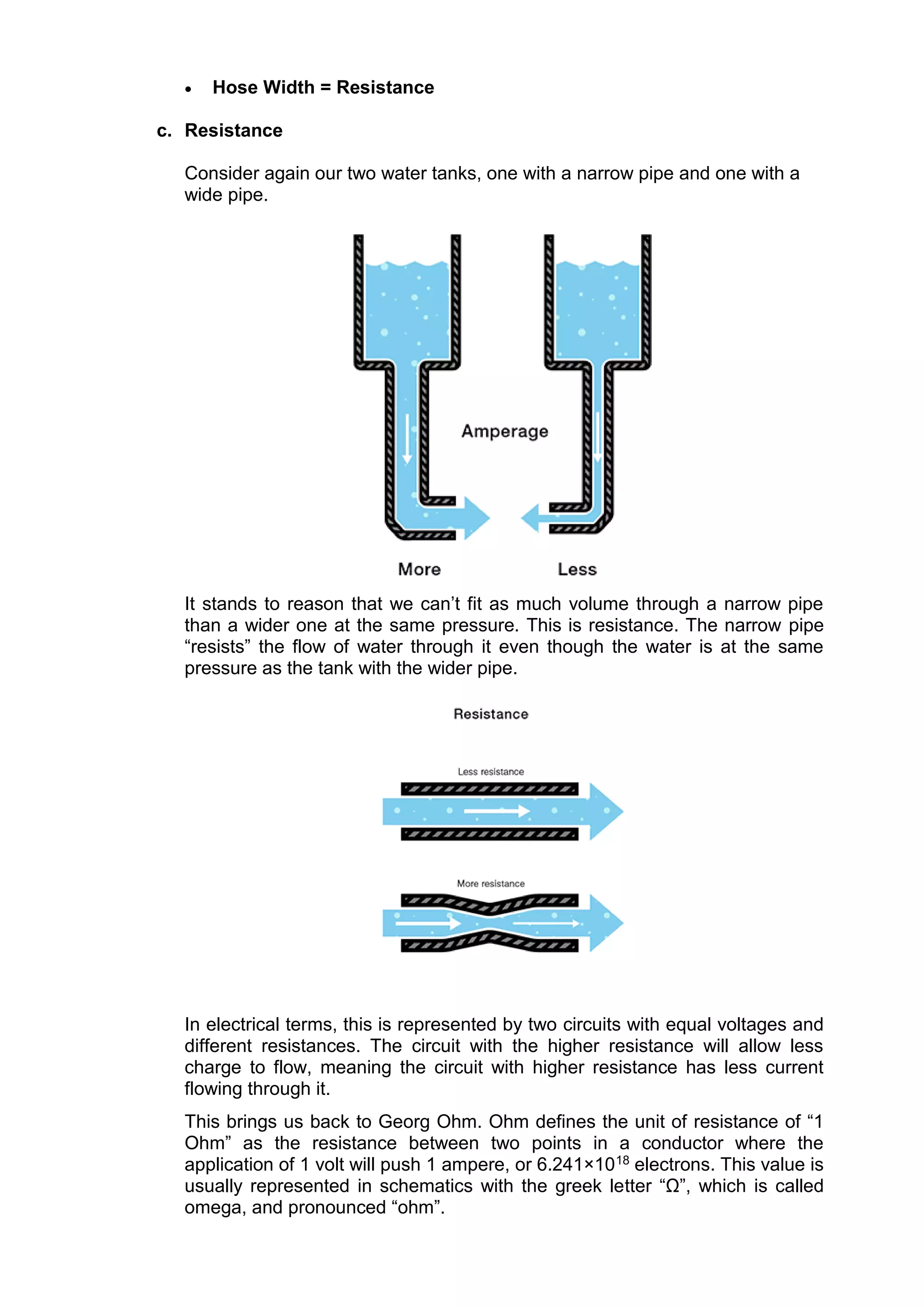
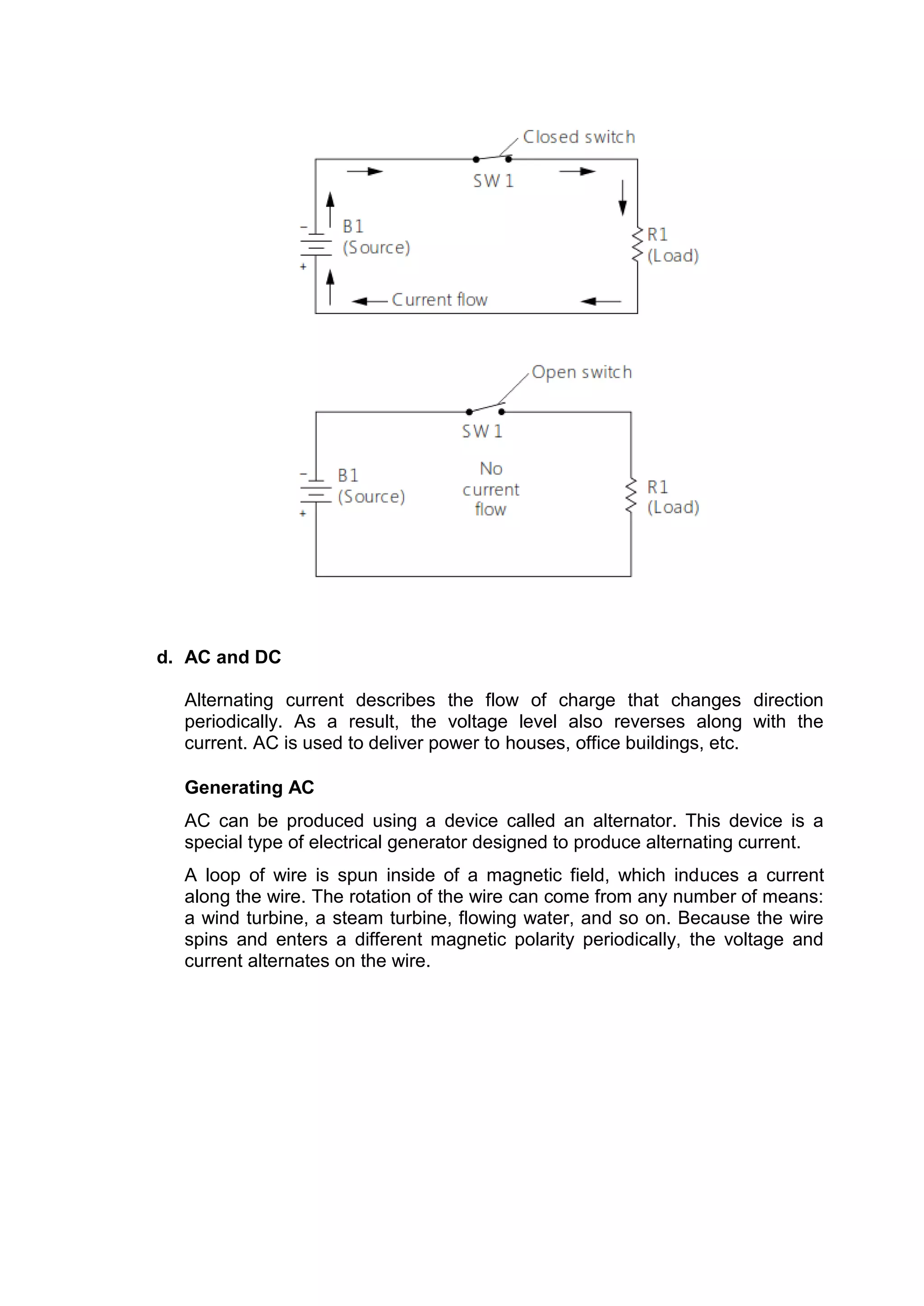
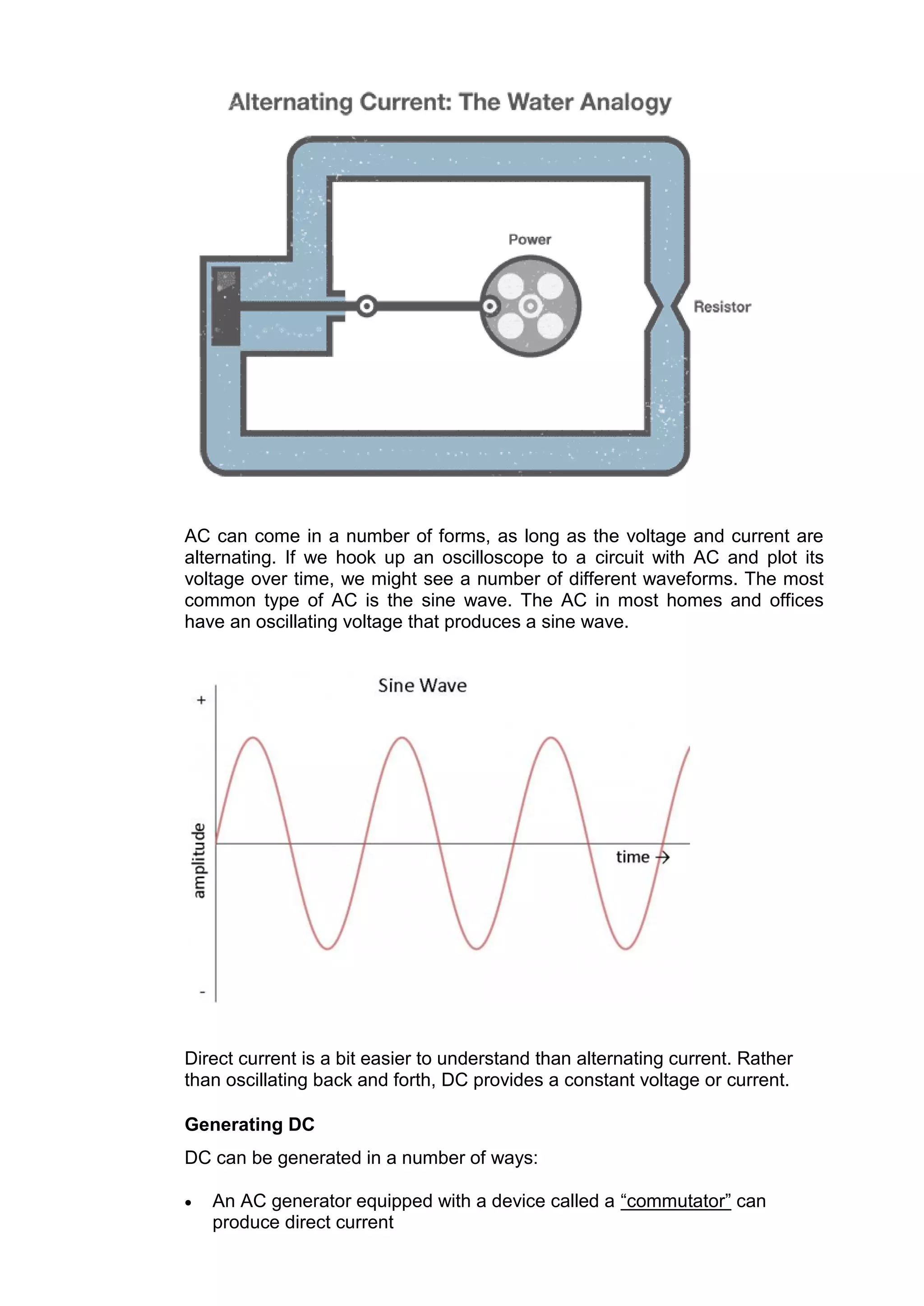
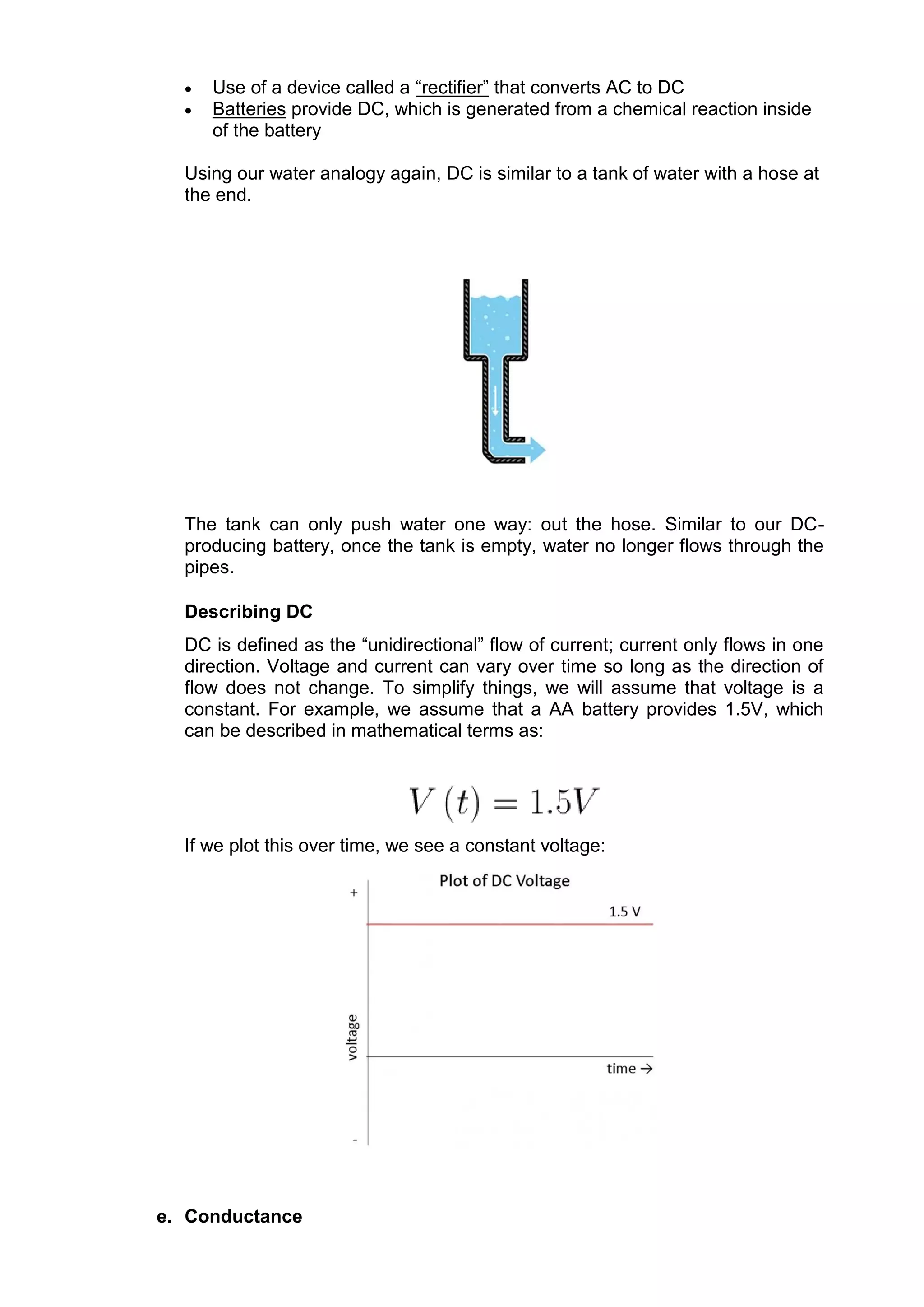
This tutorial provides an introduction to basic electronics components and concepts. It discusses resistors, potentiometers, capacitors, diodes, inductors, transistors, integrated circuits, and component symbols. It also covers characteristics of electricity including voltage, current, resistance, alternating current (AC), direct current (DC), conductance, and power. Ohm's law and circuit analysis formulas for parallel, series, and series-parallel circuits are presented. Power is defined as the rate at which energy is absorbed or produced in a circuit.


