Voltage:
• Potential refersto the the possibility of doing work.
• The symbol for potential difference is E (for electromotive
force)
• The practical unit of potential difference is the volt (V)
• 1 volt is a measure of the amount of work required to move
1C of charge
3.
Current:
• When acharge is forced to move because of a potential
difference (voltage) current is produced.
• In conductors - free electrons can be forced to move with
relative ease, since they require little work to be moved.
• So current is charge in motion.
• The more electrons in motion the greater the current.
4.
Amperes:
• Current indicatesthe intensity of the electricity in
motion. The symbol for current is I (for intensity) and is
measured in amperes.
• The definition of current is: I = Q/T
• Where I is current in amperes, Q is charge in coulombs,
and T is time in seconds.
5.
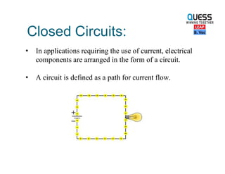
Closed Circuits:
• Inapplications requiring the use of current, electrical
components are arranged in the form of a circuit.
• A circuit is defined as a path for current flow.
6.
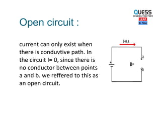
Open circuit :
currentcan only exist when
there is conduvtive path. In
the circuit I= 0, since there is
no conductor between points
a and b. we reffered to this as
an open circuit.
7.
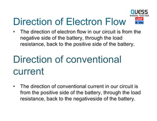
Direction of ElectronFlow
• The direction of electron flow in our circuit is from the
negative side of the battery, through the load
resistance, back to the positive side of the battery.
Direction of conventional
current
• The direction of conventional current in our circuit is
from the positive side of the battery, through the load
resistance, back to the negativeside of the battery.
8.
Direct Current:
• Circuitsthat are powered by battery sources are termed
direct current circuits.
• It is the flow of charges in just one direction
Alternating Current:
• An alternating voltage source periodically alternates or
reverses in polarity.
• The resulting current, therefore, periodically reverses in
direction.
9.
Resistance:
• Opposition tothe flow of current is termed
resistance.
• The fact that a wire can become hot from the flow
of current is evidence of resistance.
• Conductors have very little resistance.
• Insulators have large amounts of resistance.
10.
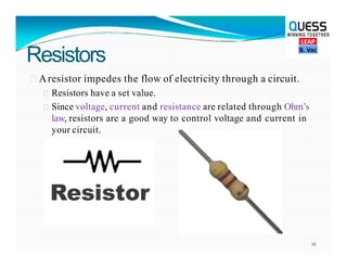
Resistors
Aresistor impedesthe flow of electricity through a circuit.
Resistors have a set value.
Since voltage, current and resistance are related through Ohm’s
law, resistors are a good way to control voltage and current in
your circuit.
10
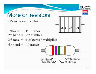
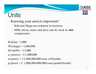
Units
Knowing your unitsisimportant!
Kilo and Mega are common in resistors
Milli, micro, nano and pico can be used in other
components
K(kilo) =1,000
M (mega) = 1,000,000
M (milli) = 1/1,000
u (micro) =1/1,000,000
n (nano) = 1/1,000,000,000 (one trillionth)
p (pico) = 1/ 1,000,000,000,000 (one quadrillionth)
13
14.
Ohm’s Law
• Theamount of current in a circuit is dependent on its
resistance and the applied voltage. Specifically I = V/R
• If you know any two of the factors V, I, and R you can
calculate the third.
• Current I = V/R
• Voltage V = IR
• Resistance R = V/I
15.
Power:
• The unitof electrical power is the watt.
• Power is how much work is done over time.
• One watt of power is equal to the work done in one
second by one volt moving one coulomb of charge.
Since one coulomb a second is an ampere:
• Power in watts = volts x amperes
• P = V x I
• P = I² x R
• P = V² / R
16.
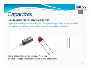
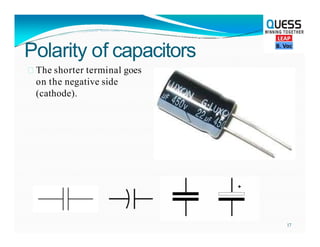
Capacitors
Acapacitor stores electricalenergy.
Capacitanceis measured in Farads. The small capacitors usually used in
electronics are often measured in microfarads and nanofarads.
Some capacitors are polarized. Note the
different length terminals on one of the capacitors.
16
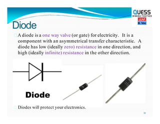
Diode
A diode isa one way valve (or gate) for electricity. It is a
component with an asymmetrical transfer characteristic. A
diode has low (ideally zero) resistance in one direction, and
high (ideally infinite) resistance in the other direction.
Diodes will protect your electronics.
18
19.
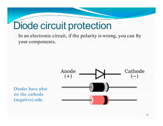
Diode circuit protection
In an electronic circuit, if the polarity is wrong, you can fry
your components.
Diodes have abar
on the cathode
(negative) side.
19
20.
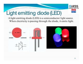
Light emitting diode(LED)
Alight emitting diode (LED) is a semiconductor light source.
When electricity is passing through the diode, it emits light.
20
21.
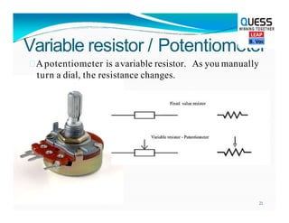
Variable resistor /Potentiometer
Apotentiometer is avariable resistor. As you manually
turn a dial, the resistance changes.
21
22.
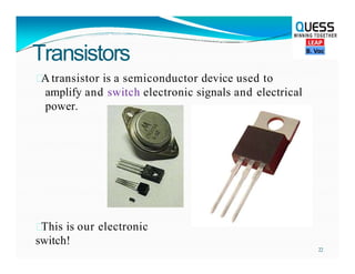
Transistors
A transistor isa semiconductor device used to
amplify and switch electronic signals and electrical
power.
This is our electronic
switch!
22
23.
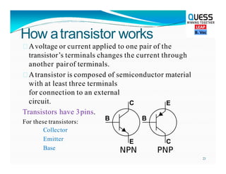
How atransistor works
Avoltageor current applied to one pair of the
transistor’s terminals changes the current through
another pairof terminals.
Atransistor is composed of semiconductor material
with at least three terminals
for connection to an external
circuit.
Transistors have 3pins.
For these transistors:
Collector
Emitter
Base
23
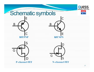
24.
T
erminology
Useful as amplifiers.
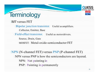
BJTversusFET
Bipolar junction transistor.
Collector, Emitter, Base
Useful as motordrivers.
Field-effect transistor.
Source, Drain, Gate
MOSFET: Metal-oxide-semiconductor FET
NPN (N-channel FET) versus PNP (P-channel FET)
NPN versus PNP is how the semiconductors are layered.
NPN: Not pointing in
PNP: Pointing in permanently
24
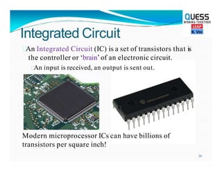
Integrated Circuit
An IntegratedCircuit (IC) is a set of transistors that is
the controller or ‘brain’of an electronic circuit.
An input is received, an output is sent out.
Modern microprocessor ICs can have billions of
transistors per square inch!
26
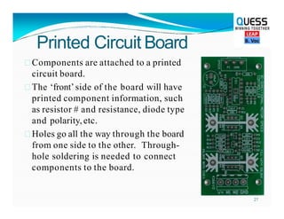
27.
Printed Circuit Board
Componentsare attached to a printed
circuit board.
The ‘front’side of the board will have
printed component information, such
as resistor # and resistance, diode type
and polarity,etc.
Holes go all the way through the board
from one side to the other. Through-
hole soldering is needed to connect
components to the board.
27
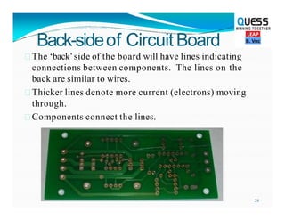
28.
Back-sideof Circuit Board
The‘back’side of the board will have lines indicating
connections between components. The lines on the
back are similar to wires.
Thicker lines denote more current (electrons) moving
through.
Components connect the lines.
28