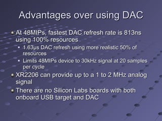
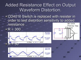
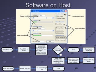
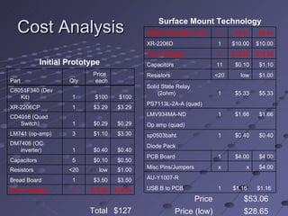
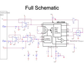
This document describes the design and implementation of a USB controlled function generator using a XR-2206 analog signal generator chip and a Silicon Labs C8051F340 microcontroller. Key features include programmable signal generation over a wide frequency range that can be controlled from a PC. The design provides advantages over a completely digital approach such as faster analog signal generation.
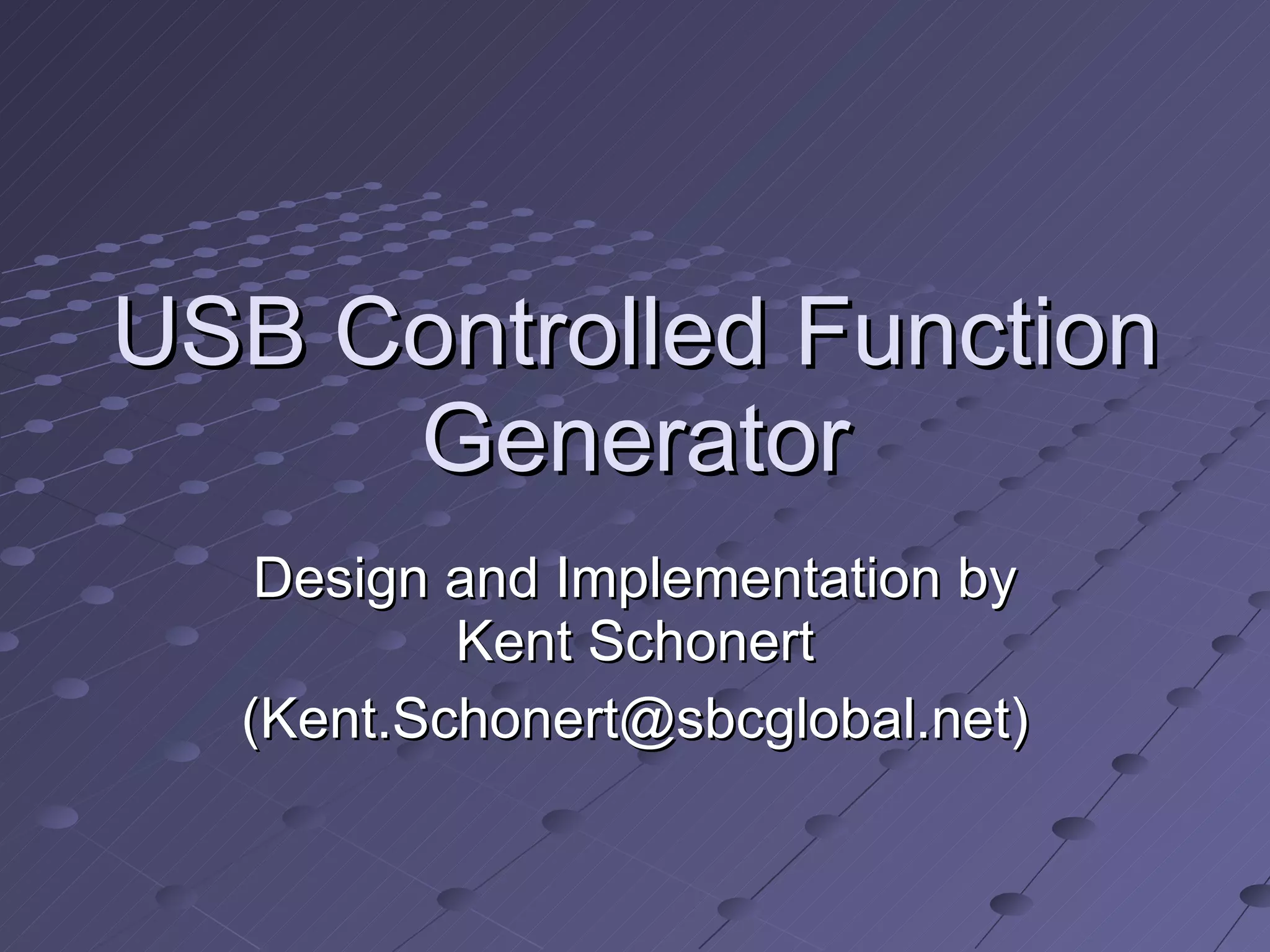
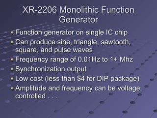
![USB Data Exchange PC Host Read Request In USB Buffer Out Data PC Host In USB Buffer Out Data Data to Target Device Data From Target Device Packet type/# Information In_Packet[0] Limit(s) Hit In_Packet[1] A/D Conversion In_Packet[2] Port1 Status In_Packet[3] Amp. PCA Value In_Packet[4] Freq. PCA Value Out_Packet[0] Amp. Hi Byte Out_Packet[1] Amp. Lo Byte Out_Packet[2] Freq. Hi Byte Out_Packet[3] Freq. Lo Byte Out_Packet[4] Freq. Multiplier Out_Packet[5] Out_Packet[6] Waveform Select](https://image.slidesharecdn.com/usbcontrolledfunctiongenerator-091215100412-phpapp01/85/Usb-Controlled-Function-Generator-15-320.jpg)


![RF Module Design - [Chapter 4] Transceiver Architecture](https://cdn.slidesharecdn.com/ss_thumbnails/rfch4-150613070346-lva1-app6891-thumbnail.jpg?width=640&height=640&fit=bounds)


![Multiband Transceivers - [Chapter 5] Software-Defined Radios](https://cdn.slidesharecdn.com/ss_thumbnails/ch5-150613070934-lva1-app6892-thumbnail.jpg?width=640&height=640&fit=bounds)


![Multiband Transceivers - [Chapter 3] Basic Concept of Comm. Systems](https://cdn.slidesharecdn.com/ss_thumbnails/ch3-150613070933-lva1-app6892-thumbnail.jpg?width=640&height=640&fit=bounds)

![Multiband Transceivers - [Chapter 7] Multi-mode/Multi-band GSM/GPRS/TDMA/AMP...](https://cdn.slidesharecdn.com/ss_thumbnails/ch7-150613070936-lva1-app6892-thumbnail.jpg?width=640&height=640&fit=bounds)