Downloaded 43 times
![DIGITAL SIGNAL PROCESSING [2171003]
Lab Manual 2016
Name:
Enrollment No. :](https://image.slidesharecdn.com/csxsmkxtq4kkseqjd3qv-signature-68dab935c2a01a35efd8d2ebd44a5ad168bbbaf9922e9d1d3c0aa0ae3b2b0151-poli-170324090758/75/Dsp-manual-1-2048.jpg)
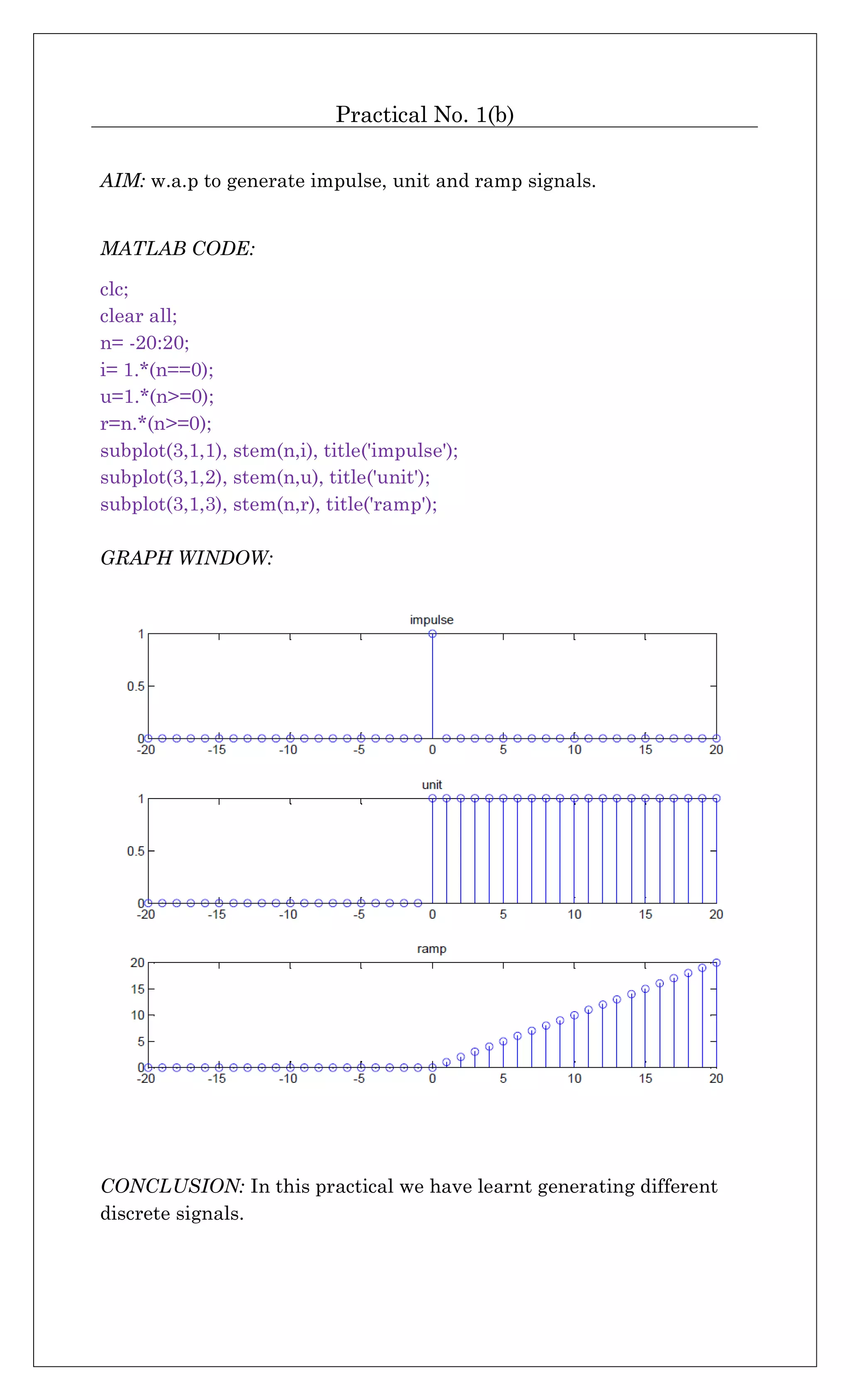
![Practical No. 2
AIM: w.a.p. for convolution and deconvolution of given sequence.
MATLAB CODE:
clc;
clear all;
x= input('enter x:');
h= input('enter h:');
c= conv(x,h);
display('output by conv is:'); c
d= deconv(c,h);
display('output after deconvolution is:'); d
COMMAND WINDOW:
enter x:[1 2 5 3 6]
enter h:[2 6]
output by conv is:
c =
2 10 22 36 30 36
output after deconvolution is:
d =
1 2 5 3 6
>>
CONCLUSION: In this practical we have learnt about functions ‘conv’
and ‘deconv’ for convolution and deconvolution.](https://image.slidesharecdn.com/csxsmkxtq4kkseqjd3qv-signature-68dab935c2a01a35efd8d2ebd44a5ad168bbbaf9922e9d1d3c0aa0ae3b2b0151-poli-170324090758/75/Dsp-manual-5-2048.jpg)
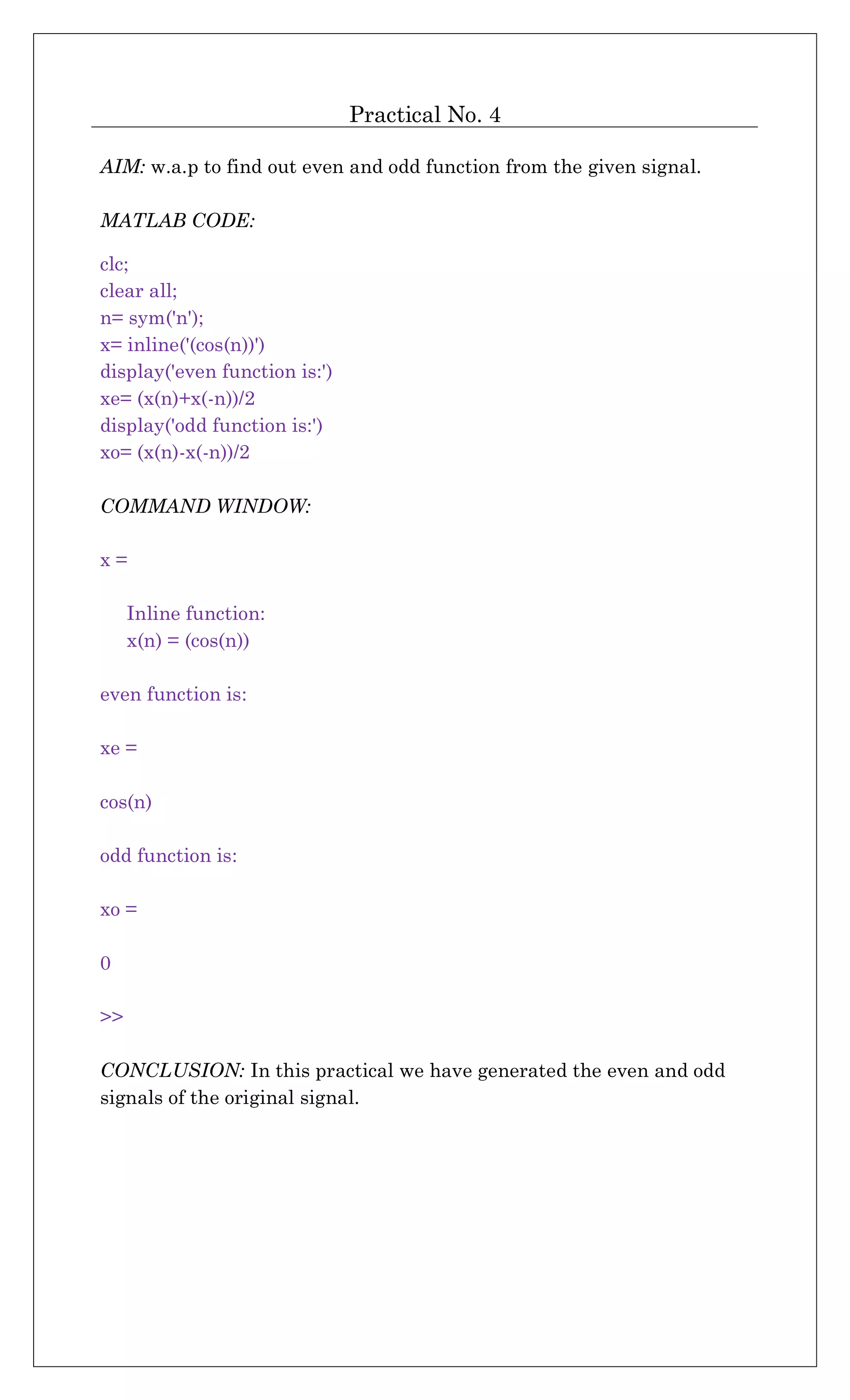
![Practical No. 3
AIM: w.a.p. to fold the given sequence.
MATLAB CODE:
clc;
clear all;
n= [1 2 3 4 5 6];
a= [4 2 5 6 9 7];
subplot(2,1,1), stem(n,a), grid('on'), title('input');
n1= -fliplr(n);
a1= fliplr(a);
subplot(2,1,2), stem(n1,a1), grid('on'), title('output');
GRAPH WINDOW:
CONCLUSION: In this practical we have learnt about using ‘fliplr’
command for folding of sequences.](https://image.slidesharecdn.com/csxsmkxtq4kkseqjd3qv-signature-68dab935c2a01a35efd8d2ebd44a5ad168bbbaf9922e9d1d3c0aa0ae3b2b0151-poli-170324090758/75/Dsp-manual-6-2048.jpg)
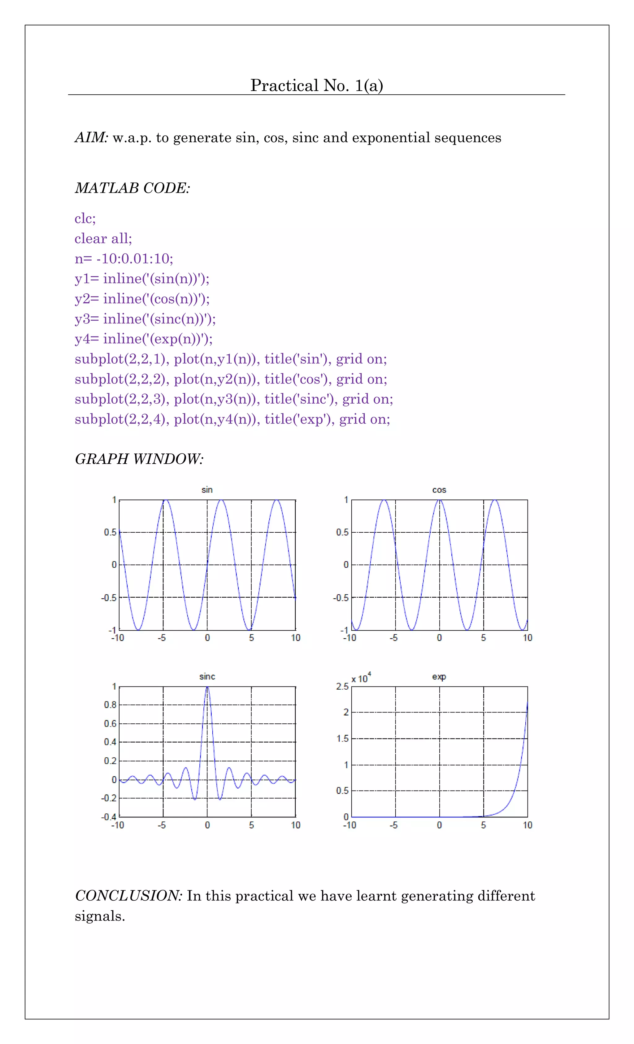
![Practical No. 5(a)
AIM: w.a.p. to find out transfer function of the system from zeros and poles.
MATLAB CODE:
clc;
clear all;
z= input('enter zeros as column vector:')
p= input('enter poles as row vector:')
k= input('enter gain in square bracket:')
[num den]=zp2tf(z,p,k);
display('tansfer function is:')
printsys(num,den,'s')
COMMAND WINDOW:
enter zeros as column vector:[1;2]
z =
1
2
enter poles as row vector:[1 3 2]
p =
1 3 2
enter gain in square bracket:[1]
k =
1
tansfer function is:
num/den =
s^2 - 3 s + 2
----------------------
s^3 - 6 s^2 + 11 s - 6
>>
CONCLUSION: In this
practical we have used
command ‘zp2tf’ for getting
transfer function from zeros
and poles.](https://image.slidesharecdn.com/csxsmkxtq4kkseqjd3qv-signature-68dab935c2a01a35efd8d2ebd44a5ad168bbbaf9922e9d1d3c0aa0ae3b2b0151-poli-170324090758/75/Dsp-manual-8-2048.jpg)
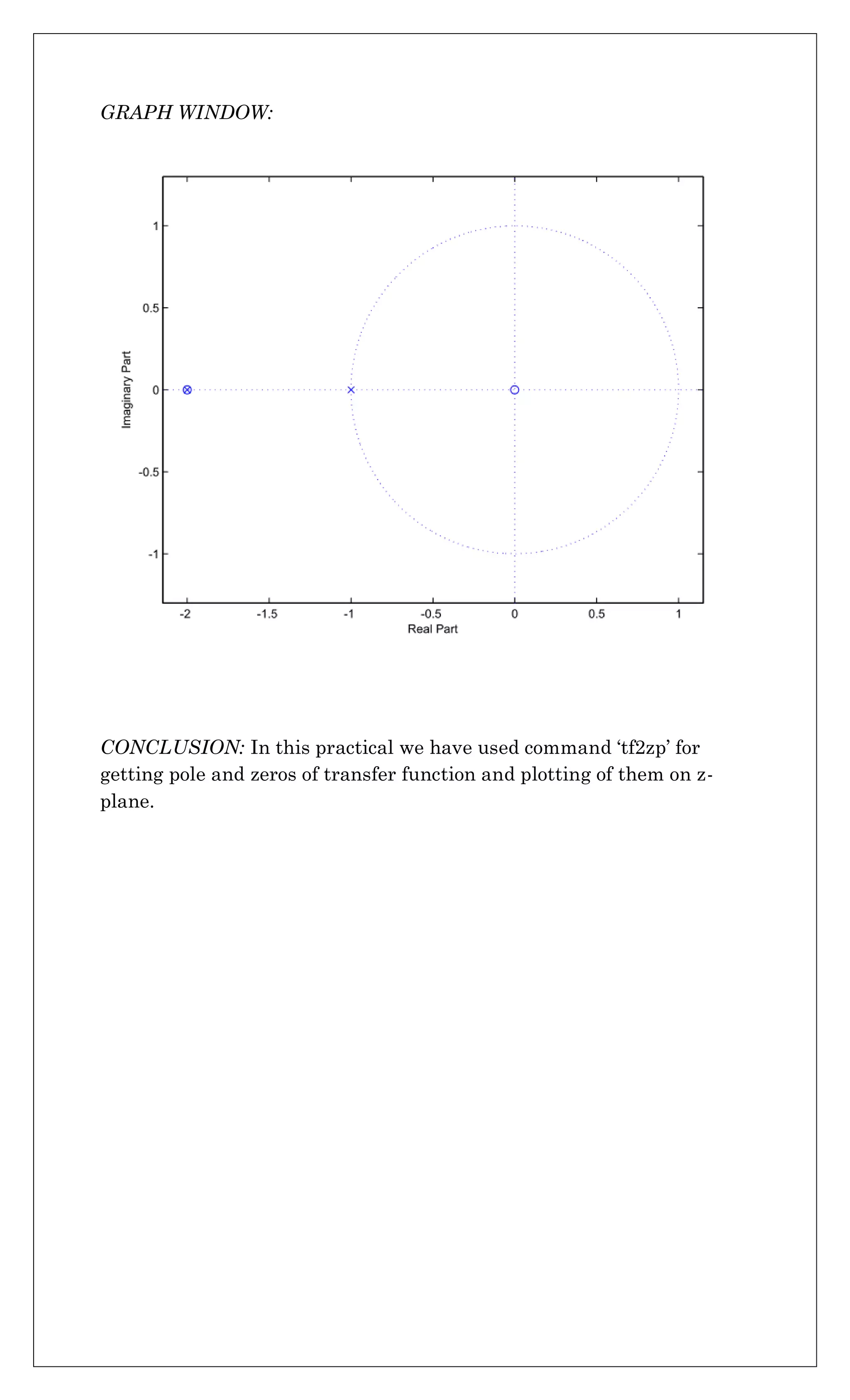
![Practical No. 5(b)
AIM: w.a.p. to find zeros and poles from Transfer function and plot them
on z-plane.
MATLAB CODE:
clc;
clear all
num= input('enter num co-efficient as row vector:');
den= input('enter den co-efficient as row vector:');
[z p k]=tf2zp(num,den)
zplane(num, den)
COMMAND WINDOW:
enter num co-efficient as row vector:[1 2]
enter den co-efficient as row vector:[1 3 2]
z =
-2
p =
-2
-1
k =
1
>>](https://image.slidesharecdn.com/csxsmkxtq4kkseqjd3qv-signature-68dab935c2a01a35efd8d2ebd44a5ad168bbbaf9922e9d1d3c0aa0ae3b2b0151-poli-170324090758/75/Dsp-manual-9-2048.jpg)
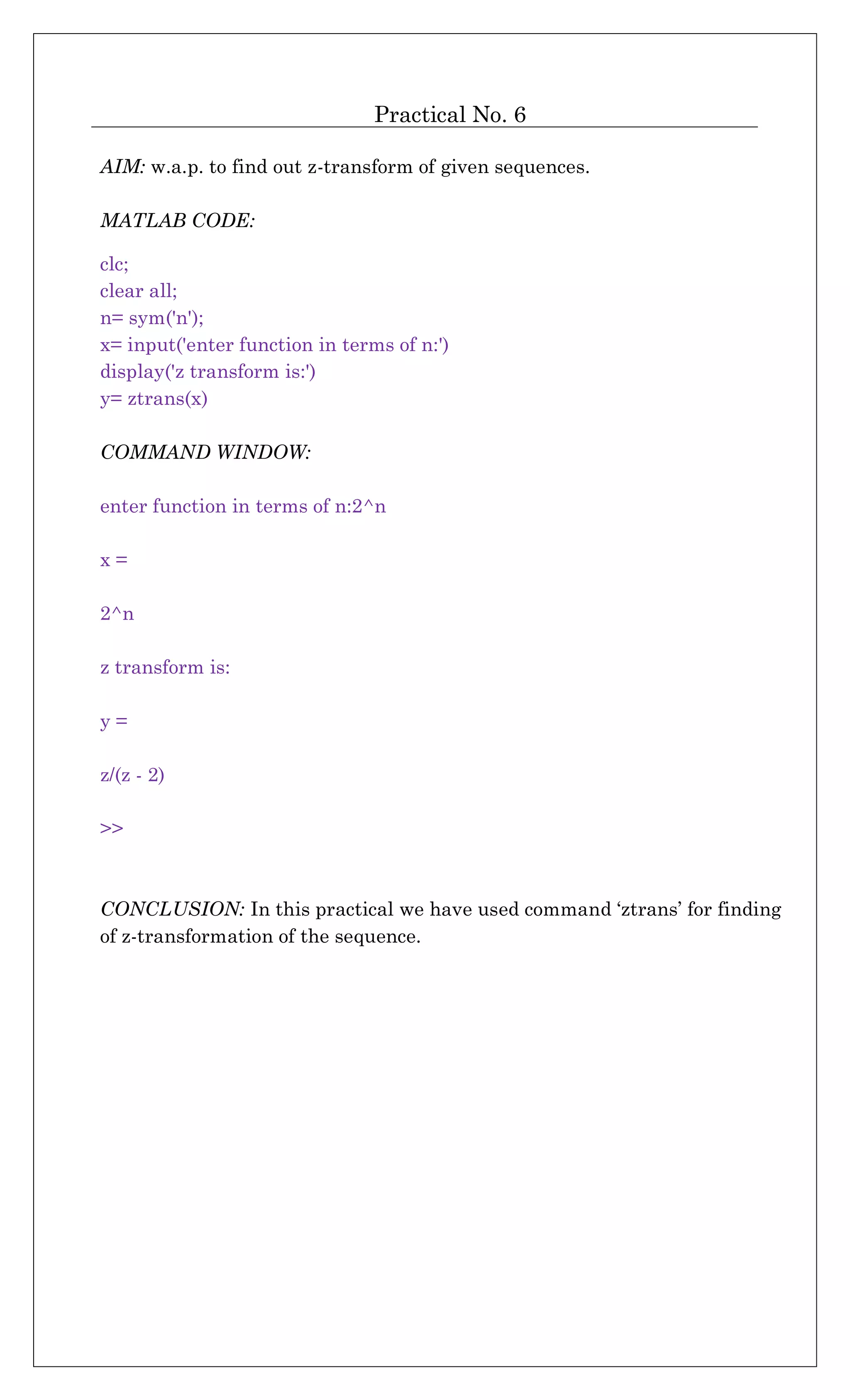
![Practical No. 7
AIM: w.a.p. for up sampling and down sampling of sequence.
MATLAB CODE:
clc;
clear all;
x= input(' enter sequence:')
a= input(' sample factor:')
u= upsample(x,a)
d= downsample(x,a)
COMMAND WINDOW:
enter sequence:[1 7 3 6 4 9]
x =
1 7 3 6 4 9
sample factor:2
a =
2
u =
1 0 7 0 3 0 6 0 4 0 9 0
d =
1 3 4
>>
CONCLUSION: In this practical we have used command ‘upsample’ and
‘downsample’ for up and down sampling of the sequence.](https://image.slidesharecdn.com/csxsmkxtq4kkseqjd3qv-signature-68dab935c2a01a35efd8d2ebd44a5ad168bbbaf9922e9d1d3c0aa0ae3b2b0151-poli-170324090758/75/Dsp-manual-12-2048.jpg)
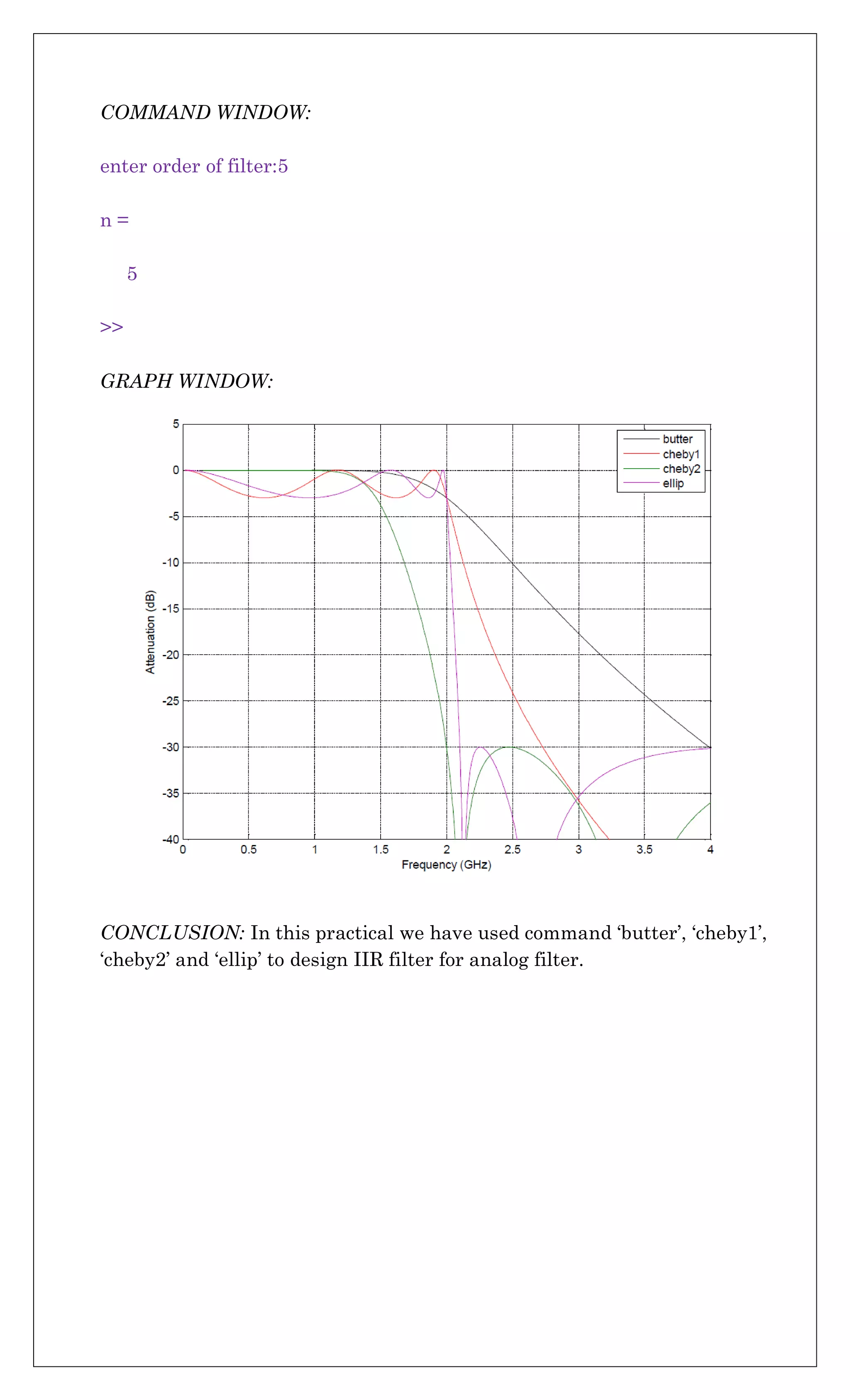
![Practical No. 8
AIM: w.a.p. to design IIR filter for analog filter using butterworth,
chebychev1, chebychev2 and using elliptical.
MATLAB CODE:
clc;
clear all;
n = input('enter order of filter:')
f = 2e9;
[zb,pb,kb] = butter(n,2*pi*f,'s');
[bb,ab] = zp2tf(zb,pb,kb);
[hb,wb] = freqs(bb,ab,4096);
[z1,p1,k1] = cheby1(n,3,2*pi*f,'s');
[b1,a1] = zp2tf(z1,p1,k1);
[h1,w1] = freqs(b1,a1,4096);
[z2,p2,k2] = cheby2(n,30,2*pi*f,'s');
[b2,a2] = zp2tf(z2,p2,k2);
[h2,w2] = freqs(b2,a2,4096);
[ze,pe,ke] = ellip(n,3,30,2*pi*f,'s');
[be,ae] = zp2tf(ze,pe,ke);
[he,we] = freqs(be,ae,4096);
plot(wb/(2e9*pi),mag2db(abs(hb)))
hold on
plot(w1/(2e9*pi),mag2db(abs(h1)))
plot(w2/(2e9*pi),mag2db(abs(h2)))
plot(we/(2e9*pi),mag2db(abs(he)))
axis([0 4 -40 5])
grid on
xlabel('Frequency (GHz)')
ylabel('Attenuation (dB)')
legend('butter','cheby1','cheby2','ellip')](https://image.slidesharecdn.com/csxsmkxtq4kkseqjd3qv-signature-68dab935c2a01a35efd8d2ebd44a5ad168bbbaf9922e9d1d3c0aa0ae3b2b0151-poli-170324090758/75/Dsp-manual-13-2048.jpg)
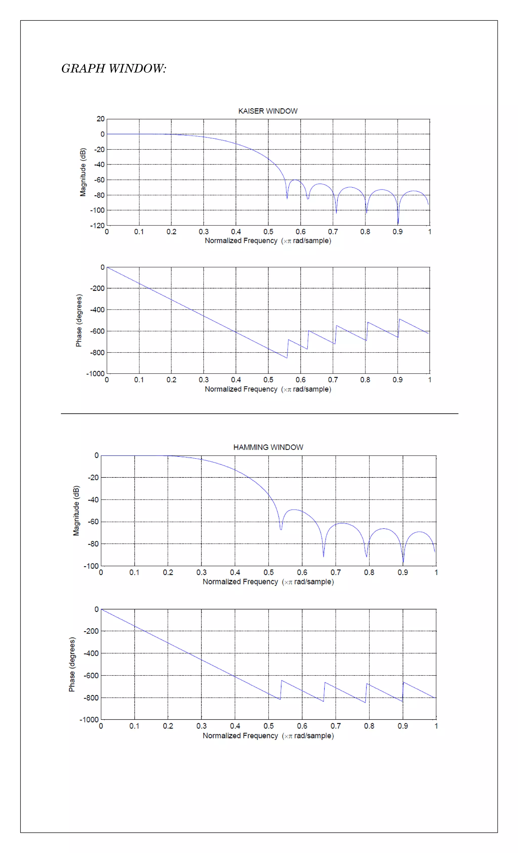

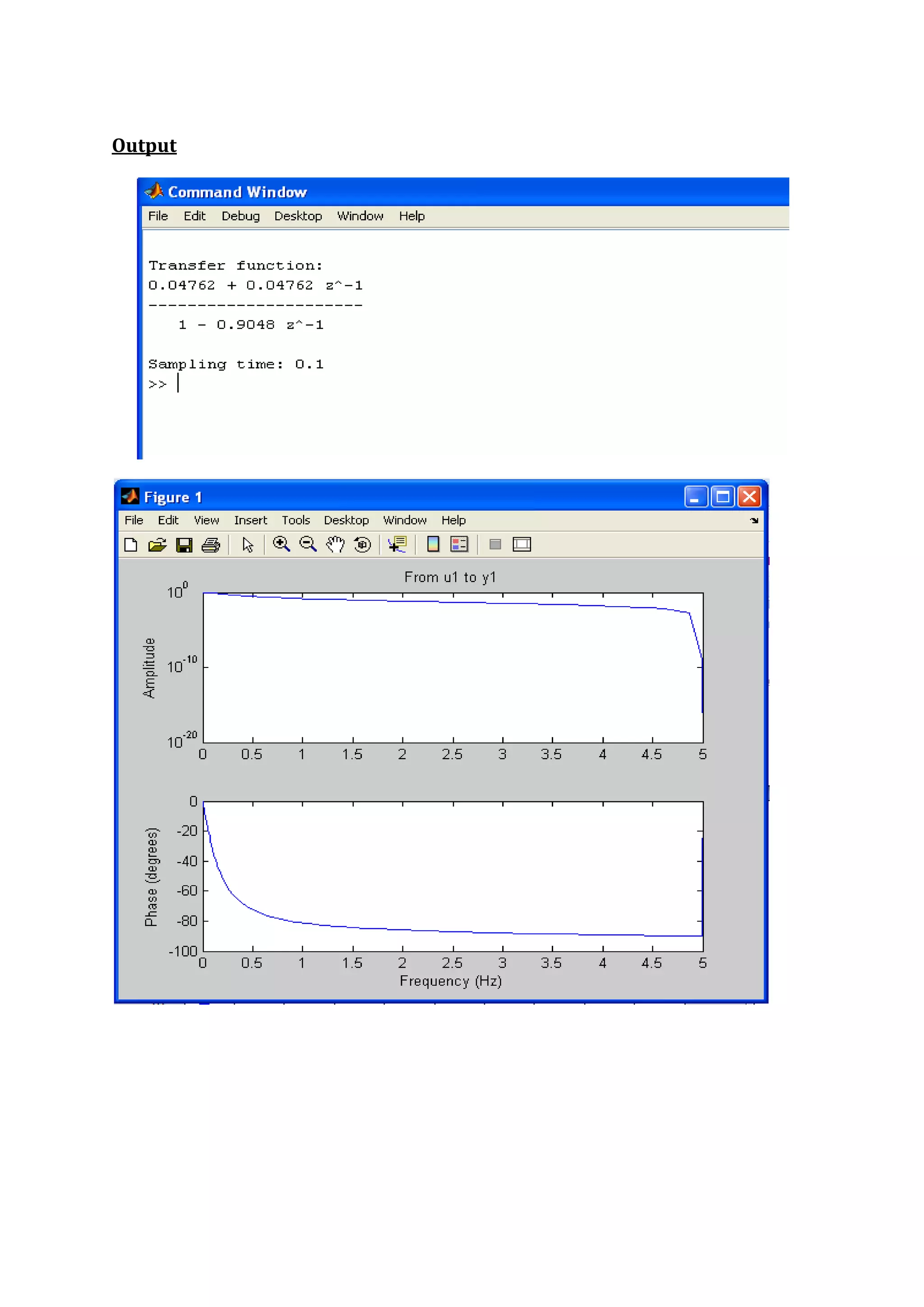
![EXPERIMENT No.11
AIM: To Study Analog to Digital Filter Transformation.
1) Use impinvar to perform analog to digital filter transformation of
Take T=1s.
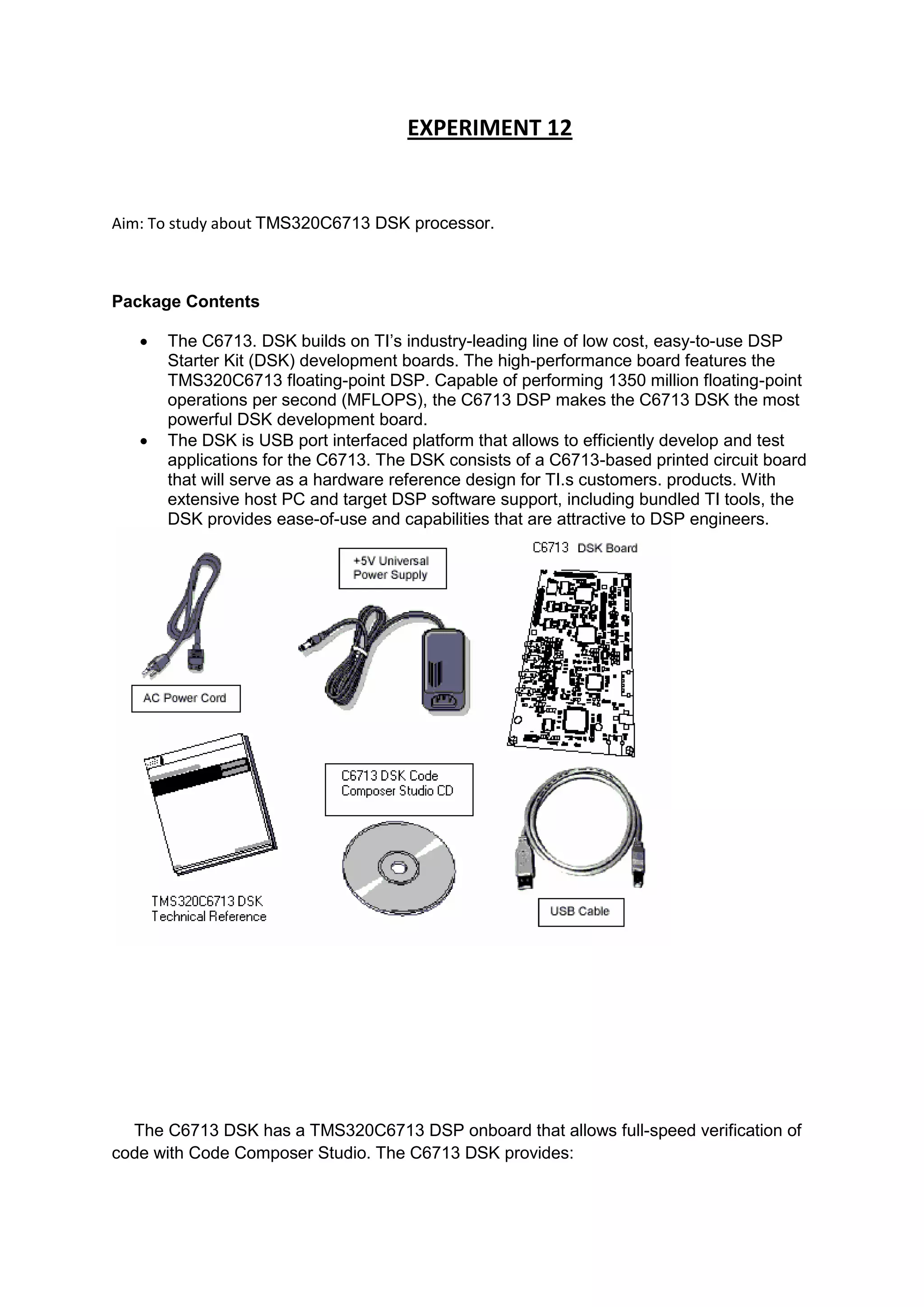
2) Use bilinear to perform analog to digital transformation of
Take Ts = 0.1s.
Description:
The classic IIR filter design technique includes the following steps.
1) Find a high pass filter with cutoff frequency of 1 and translate this
prototype filter to the desired band configuration.
2) Transform the filter to the digital domain.
3) Discretize the filter
Matlab functions can be used for filter designing are as below:
1) Impinvar [by, az] = impinvar (b, a, fs) creates a digital filter with numerator
and denominator coefficients bz and az, respectively, whose impulse
response is equal to the impulse response of the analog filter with
coefficients b and a, scaled by 1/fs. If we leave out the argument fs, or
specify fs as the empty vector [], it takes the default value of 1 Hz.
2) Bilinear -[numd,dend] = bilinear(num,den,fs) converts an s-domain transfer
function given by num and den to a discrete equivalent. Row vectors num
and den specify the coefficients of the numerator and denominator,
respectively, in descending powers of s. fs is the sampling frequency in
hertz. Bilinear returns the discrete equivalent in row vectors numd and dend
in descending powers of z (ascending powers of z-1).
Answer:
1) z = [1 0.2];
p = [1 0.4 9.04];
[num den]= impinvar(z,p,1);
sys= filt(num,den,1)
ffplot(sys)
Output:](https://image.slidesharecdn.com/csxsmkxtq4kkseqjd3qv-signature-68dab935c2a01a35efd8d2ebd44a5ad168bbbaf9922e9d1d3c0aa0ae3b2b0151-poli-170324090758/75/Dsp-manual-22-2048.jpg)
![2) z=[1];
p=[1 1];
[num den] = bilinear(z,p,10);
sys= filt(num,den,0.1)
ffplot(sys)](https://image.slidesharecdn.com/csxsmkxtq4kkseqjd3qv-signature-68dab935c2a01a35efd8d2ebd44a5ad168bbbaf9922e9d1d3c0aa0ae3b2b0151-poli-170324090758/75/Dsp-manual-23-2048.jpg)


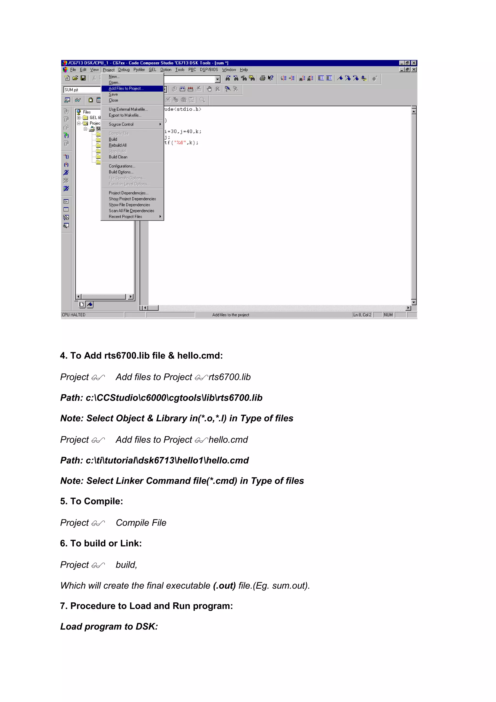
![File Load program sum. out
8. To execute project:
Debug Run.
Program:
‘C’ Program to Implement Impulse response:
#include <stdio.h>
#define Order 2
#define Len 10
float y[Len]={0,0,0},sum;
main()
{
int j,k;
float a[Order+1]={0.1311, 0.2622, 0.1311};
float b[Order+1]={1, -0.7478, 0.2722};
for(j=0;j<Len;j++)
{
sum=0;
for(k=1;k<=Order;k++)
{
if((j-k)>=0)
sum=sum+(b[k]*y[j-k]);
}
if(j<=Order)
{
y[j]=a[j]-sum;
}
else
{](https://image.slidesharecdn.com/csxsmkxtq4kkseqjd3qv-signature-68dab935c2a01a35efd8d2ebd44a5ad168bbbaf9922e9d1d3c0aa0ae3b2b0151-poli-170324090758/75/Dsp-manual-32-2048.jpg)
![y[j]=-sum;
}
printf("Respose[%d] = %fn",j,y[j]);
}
}
‘C‘ Program to Implement Difference Equation
#include <stdio.h>
#include<math.h>
#define FREQ 400
float y[3]={0,0,0};
float x[3]={0,0,0};
float z[128],m[128],n[128],p[128];
main()
{
int i=0,j;
float a[3]={ 0.072231,0.144462,0.072231};
float b[3]={ 1.000000,-1.109229,0.398152};
for(i=0;i<128;i++)
{
m[i]=sin(2*3.14*FREQ*i/24000);
}
for(j=0;j<128;j++)
{
x[0]=m[j];
y[0] = (a[0] *x[0]) +(a[1]* x[1] ) +(x[2]*a[2]) - (y[1]*b[1])-
(y[2]*b[2]);
z[j]=y[0];
y[2]=y[1];
y[1]=y[0];
x[2]=x[1];](https://image.slidesharecdn.com/csxsmkxtq4kkseqjd3qv-signature-68dab935c2a01a35efd8d2ebd44a5ad168bbbaf9922e9d1d3c0aa0ae3b2b0151-poli-170324090758/75/Dsp-manual-33-2048.jpg)
![x[1] = x[0];}](https://image.slidesharecdn.com/csxsmkxtq4kkseqjd3qv-signature-68dab935c2a01a35efd8d2ebd44a5ad168bbbaf9922e9d1d3c0aa0ae3b2b0151-poli-170324090758/75/Dsp-manual-34-2048.jpg)

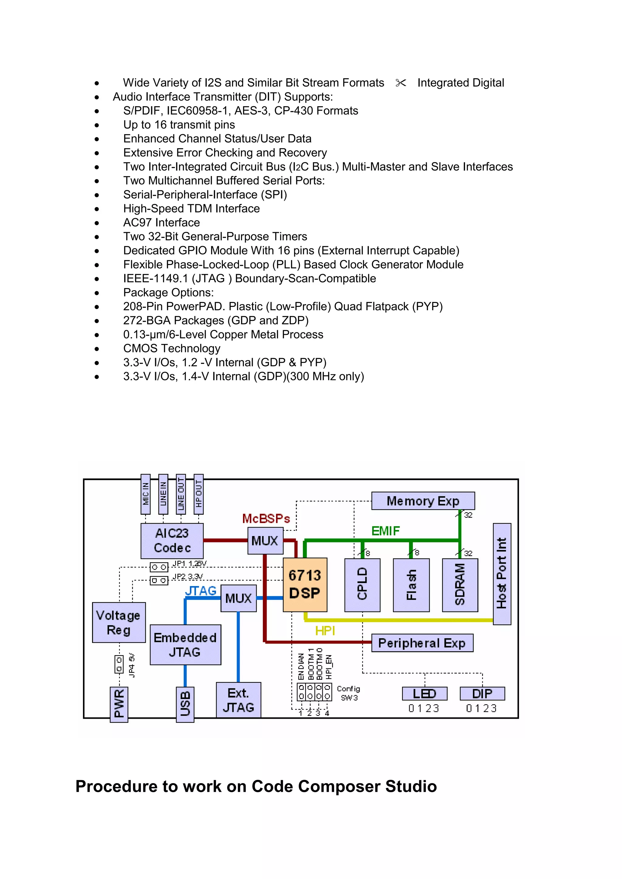
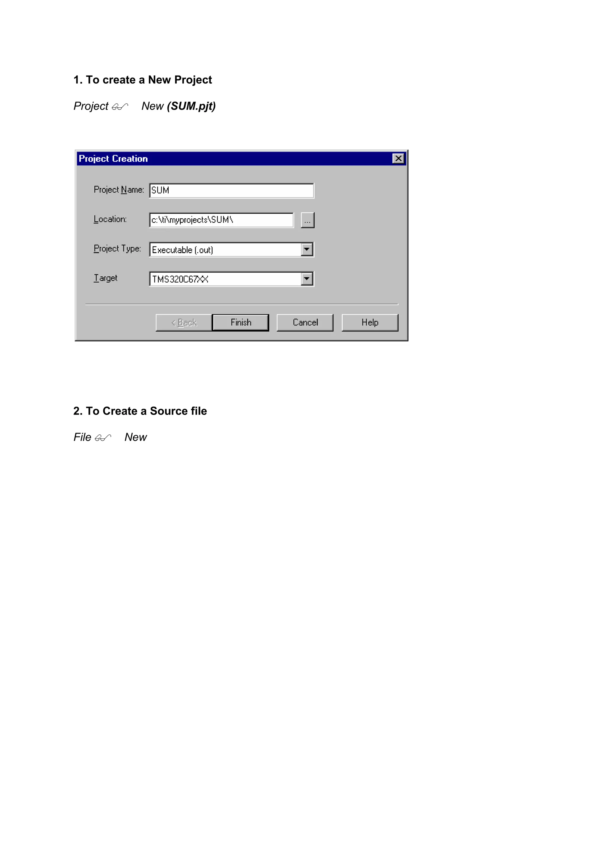
This document discusses the TMS320C6713 digital signal processor (DSP) development kit (DSK). The DSK features the high-performance TMS320C6713 floating-point DSP chip capable of 1350 million floating point operations per second. The DSK allows for efficient development and testing of applications for the C6713 DSP. It includes onboard memory, an analog interface circuit for data conversion, I/O ports, and JTAG emulation support. The DSK also includes a stereo codec for analog audio input/output.


![射頻電子 - [第一章] 知識回顧與通訊系統簡介](https://cdn.slidesharecdn.com/ss_thumbnails/ch1-150613065058-lva1-app6891-thumbnail.jpg?width=640&height=640&fit=bounds)


![RF Module Design - [Chapter 6] Power Amplifier](https://cdn.slidesharecdn.com/ss_thumbnails/rfch6-150613070347-lva1-app6891-thumbnail.jpg?width=640&height=640&fit=bounds)


![Multiband Transceivers - [Chapter 7] Multi-mode/Multi-band GSM/GPRS/TDMA/AMP...](https://cdn.slidesharecdn.com/ss_thumbnails/ch7-150613070936-lva1-app6892-thumbnail.jpg?width=640&height=640&fit=bounds)
![RF Module Design - [Chapter 1] From Basics to RF Transceivers](https://cdn.slidesharecdn.com/ss_thumbnails/rfch1-150613070344-lva1-app6892-thumbnail.jpg?width=640&height=640&fit=bounds)
![RF Module Design - [Chapter 8] Phase-Locked Loops](https://cdn.slidesharecdn.com/ss_thumbnails/rfch8-150613070348-lva1-app6892-thumbnail.jpg?width=640&height=640&fit=bounds)


![Robophonia[2]](https://cdn.slidesharecdn.com/ss_thumbnails/robophonia2-170327092407-thumbnail.jpg?width=640&height=640&fit=bounds)


![DSP_Lab_MAnual_-_Final_Edition[1].docx](https://cdn.slidesharecdn.com/ss_thumbnails/dsplabmanual-finaledition1-231105142533-78903af8-thumbnail.jpg?width=640&height=640&fit=bounds)