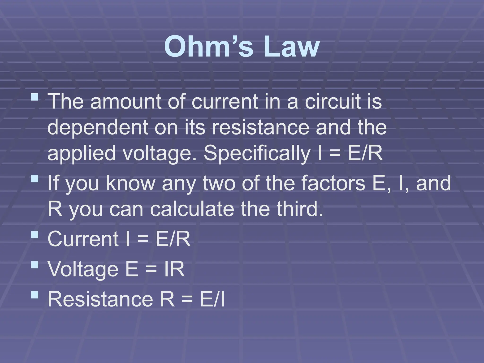
Objectives
•Define basic components of electricity
•Recognize the 3 electrical classifications of
materials
•Compare and contrast AC vs. DC
•Explain the concept of grounding
•Use Ohm’s law and Watt’s law to express
the relationship between current, voltage, and
resistance
Basic Electronics I
Electricity can be broken
down into:
 Electric Charge
 Voltage
 Current
 Resistance
Negative & Positive Charges
 What do the effects of electricity in TV,
radio, a battery, and lightening all have in
common?
 Basic particles of electric charge with
opposite polarities.
Electrons
 The smallest amount of electrical charge
having the quality called negative polarity.
 Electrons orbit the center of atoms.
Protons
 The proton is a basic particle with positive
polarity.
 Protons are located in the nucleus of
atoms along with neutrons, particles which
have neutral polarity.
Electrically, all materials fall
into 1 of 3 classifications:
 Conductors
 Insulators
 Semi-Conductors
Conductors
 Have 1 valence electron
 Materials in which electrons can move
freely from atom to atom are called
conductors.
 In general all metals are good conductors.
 The purpose of conductors is to allow
electrical current to flow with minimum
resistance.
Insulators
 Have 8 valence electrons
 Materials in which electrons tend to stay put and
do not flow easily from atom to atom are termed
insulators.
 Insulators are used to prevent the flow of
electricity.
 Insulating materials such as glass, rubber, or
plastic are also called dielectrics, meaning they
can store charges.
 Dielectric materials are used in components like
capacitors which must store electric charges.
Semi-Conductors
 Have 4 valence electrons
 Materials which are neither conductors nor
insulators
 Common semi conductor materials are carbon,
germanium and silicone.
 Used in components like transistors
The Symbol for Charge
 The symbol for charge is Q which stands
for quantity.
 The practical unit of charge is called the
coulomb (C).
 One coulomb is equal to the amount of
charge of 6.25X10¹⁸
electrons or protons
stored in a dielectric.
Voltage
 Potential refers to the the possibility of doing
work.
 Any charge has the potential to do the work of
attracting a similar charge or repulsing an
opposite charge.
 The symbol for potential difference is E (for
electromotive force)
 The practical unit of potential difference is the
volt (V)
 1 volt is a measure of the amount of work
required to move 1C of charge
Current
 When a charge is forced to move because
of a potential difference (voltage) current is
produced.
 In conductors - free electrons can be
forced to move with relative ease, since
they require little work to be moved.
 So current is charge in motion.
 The more electrons in motion the greater
the current.
Amperes
 Current indicates the intensity of the electricity in
motion. The symbol for current is I (for intensity)
and is measured in amperes.
 The definition of current is: I = Q/T
 Where I is current in amperes, Q is charge in
coulombs, and T is time in seconds.
1 ampere = 1 coulomb per
second
Resistance
 Opposition to the flow of current is termed
resistance.
 The fact that a wire can become hot from
the flow of current is evidence of
resistance.
 Conductors have very little resistance.
 Insulators have large amounts of
resistance.
Ohms
 The practical unit of resistance is the
ohm designated by the Greek letter
omega: Ω
 A resistor is an electronic component
designed specifically to provide
resistance.
Closed Circuits
 In applications requiring the use of current,
electrical components are arranged in the
form of a circuit.
 A circuit is defined as a path for current
flow.
Common Electronic
Component Symbols
A Complex Audio Circuit
Open Circuits
The Circuit is a Load on the
Voltage Source
 The circuit is where the energy of the
source (battery) is carried by means of the
current through the the various
components.
 The battery is the source, since it
provides the potential energy to be used.
 The circuit components are the load
resistance - they determines how much
current the source will produce.
Direction of Electron Flow
 The direction of electron flow in our circuit
is from the negative side of the battery,
through the load resistance, back to the
positive side of the battery.
 Inside the battery, electrons move to the
negative terminal due to chemical action,
maintaining the potential across the leads.
Electron Flow in a Simple
Circuit
DC
 Circuits that are powered by battery
sources are termed direct current
circuits.
 This is because the battery maintains the
same polarity of output voltage. The plus
and minus sides remain constant.
Waveform of DC Voltage
Characteristics of DC
 It is the flow of charges in just one
direction and...
 The fixed polarity of the applied voltage
which are characteristics of DC circuits
AC
 An alternating voltage source periodically
alternates or reverses in polarity.
 The resulting current, therefore,
periodically reverses in direction.
 The power outlet in your home is 60 cycle
ac - meaning the voltage polarity and
current direction go through 60 cycles of
reversal per second.
 All audio signals are AC also.
Waveform of AC Voltage
Complex Voltage
This is a more realistic view of what
an audio signal’s voltage would look like
Comparison of DC & AC
DC Voltage AC Voltage
Fixed polarity Reverses polarity
Can be steady or vary in
magnitude
Varies in magnitude
between reversals in
polarity
Steady value cannot be
stepped up or down by a
transformer
Used for electrical power
distribution
Electrode voltage for tube
and transistor amps
I/O signal for tube and
transistor amps
Easier to measure Easier to amplify
Heating Effects the same for both AC and DC current
Many Circuits Include both
AC & DC Voltages
 DC circuits are usually simpler than AC
circuits.
 However, the principles of DC circuits also
apply to AC circuits.
Impedance
 Impedance is resistance to current flow in
AC circuits and its symbol is .
 Impedance is also measured in ohms.
Grounding
 In the wiring of practical circuits one side of the voltage
source is usually grounded for safety.
 For 120 V - ac power lines in homes this means one side
of the voltage source is connected to a metal cold water
pipe.
 For electronic equipment, the ground just indicates a
metal chassis, which is used as a common return for
connections to the source.
Common Symbols/ Names for
Ground in Electric Circuits
Ohm’s Law
 The amount of current in a circuit is
dependent on its resistance and the
applied voltage. Specifically I = E/R
 If you know any two of the factors E, I, and
R you can calculate the third.
 Current I = E/R
 Voltage E = IR
 Resistance R = E/I
Current is Directly Proportional to
Voltage for a Constant Resistance
OHM’s LAW
Current is Inversely Proportional to
Resistance for a Constant Voltage
OHM’s LAW
Power
 The unit of electrical power is the watt.
 Power is how much work is done over time.
 One watt of power is equal to the work done in
one second by one volt moving one coulomb of
charge. Since one coulomb a second is an
ampere:
 Power in watts = volts x amperes
 P = E x I
3 Power Formulas
 P = E x I
 P = I2 x
R
 P = E2
/ R
Conversion Factors
Prefix Symbol Relation to
basic unit
Examples
Mega M 1,000,000
or 1x10⁶
5MΩ =
5x10⁶
Ω
Kilo k 1,000 or
1x10³
18kV =
18x103
V
Milli m .001 or
1x10⁻³
48 mA =
48x10-3
A
Micro  .000001 or
1x10⁻⁶
15V =
15x10-6
V

Basic electronic and electronics equipment

  • 1.
    Objectives •Define basic componentsof electricity •Recognize the 3 electrical classifications of materials •Compare and contrast AC vs. DC •Explain the concept of grounding •Use Ohm’s law and Watt’s law to express the relationship between current, voltage, and resistance Basic Electronics I
  • 2.
    Electricity can bebroken down into:  Electric Charge  Voltage  Current  Resistance
  • 3.
    Negative & PositiveCharges  What do the effects of electricity in TV, radio, a battery, and lightening all have in common?  Basic particles of electric charge with opposite polarities.
  • 4.
    Electrons  The smallestamount of electrical charge having the quality called negative polarity.  Electrons orbit the center of atoms.
  • 5.
    Protons  The protonis a basic particle with positive polarity.  Protons are located in the nucleus of atoms along with neutrons, particles which have neutral polarity.
  • 7.
    Electrically, all materialsfall into 1 of 3 classifications:  Conductors  Insulators  Semi-Conductors
  • 8.
    Conductors  Have 1valence electron  Materials in which electrons can move freely from atom to atom are called conductors.  In general all metals are good conductors.  The purpose of conductors is to allow electrical current to flow with minimum resistance.
  • 9.
    Insulators  Have 8valence electrons  Materials in which electrons tend to stay put and do not flow easily from atom to atom are termed insulators.  Insulators are used to prevent the flow of electricity.  Insulating materials such as glass, rubber, or plastic are also called dielectrics, meaning they can store charges.  Dielectric materials are used in components like capacitors which must store electric charges.
  • 10.
    Semi-Conductors  Have 4valence electrons  Materials which are neither conductors nor insulators  Common semi conductor materials are carbon, germanium and silicone.  Used in components like transistors
  • 11.
    The Symbol forCharge  The symbol for charge is Q which stands for quantity.  The practical unit of charge is called the coulomb (C).  One coulomb is equal to the amount of charge of 6.25X10¹⁸ electrons or protons stored in a dielectric.
  • 12.
    Voltage  Potential refersto the the possibility of doing work.  Any charge has the potential to do the work of attracting a similar charge or repulsing an opposite charge.  The symbol for potential difference is E (for electromotive force)  The practical unit of potential difference is the volt (V)  1 volt is a measure of the amount of work required to move 1C of charge
  • 13.
    Current  When acharge is forced to move because of a potential difference (voltage) current is produced.  In conductors - free electrons can be forced to move with relative ease, since they require little work to be moved.  So current is charge in motion.  The more electrons in motion the greater the current.
  • 14.
    Amperes  Current indicatesthe intensity of the electricity in motion. The symbol for current is I (for intensity) and is measured in amperes.  The definition of current is: I = Q/T  Where I is current in amperes, Q is charge in coulombs, and T is time in seconds.
  • 15.
    1 ampere =1 coulomb per second
  • 16.
    Resistance  Opposition tothe flow of current is termed resistance.  The fact that a wire can become hot from the flow of current is evidence of resistance.  Conductors have very little resistance.  Insulators have large amounts of resistance.
  • 17.
    Ohms  The practicalunit of resistance is the ohm designated by the Greek letter omega: Ω  A resistor is an electronic component designed specifically to provide resistance.
  • 18.
    Closed Circuits  Inapplications requiring the use of current, electrical components are arranged in the form of a circuit.  A circuit is defined as a path for current flow.
  • 19.
  • 20.
  • 21.
  • 22.
    The Circuit isa Load on the Voltage Source  The circuit is where the energy of the source (battery) is carried by means of the current through the the various components.  The battery is the source, since it provides the potential energy to be used.  The circuit components are the load resistance - they determines how much current the source will produce.
  • 23.
    Direction of ElectronFlow  The direction of electron flow in our circuit is from the negative side of the battery, through the load resistance, back to the positive side of the battery.  Inside the battery, electrons move to the negative terminal due to chemical action, maintaining the potential across the leads.
  • 24.
    Electron Flow ina Simple Circuit
  • 25.
    DC  Circuits thatare powered by battery sources are termed direct current circuits.  This is because the battery maintains the same polarity of output voltage. The plus and minus sides remain constant.
  • 26.
  • 27.
    Characteristics of DC It is the flow of charges in just one direction and...  The fixed polarity of the applied voltage which are characteristics of DC circuits
  • 28.
    AC  An alternatingvoltage source periodically alternates or reverses in polarity.  The resulting current, therefore, periodically reverses in direction.  The power outlet in your home is 60 cycle ac - meaning the voltage polarity and current direction go through 60 cycles of reversal per second.  All audio signals are AC also.
  • 29.
  • 30.
    Complex Voltage This isa more realistic view of what an audio signal’s voltage would look like
  • 31.
    Comparison of DC& AC DC Voltage AC Voltage Fixed polarity Reverses polarity Can be steady or vary in magnitude Varies in magnitude between reversals in polarity Steady value cannot be stepped up or down by a transformer Used for electrical power distribution Electrode voltage for tube and transistor amps I/O signal for tube and transistor amps Easier to measure Easier to amplify Heating Effects the same for both AC and DC current
  • 32.
    Many Circuits Includeboth AC & DC Voltages  DC circuits are usually simpler than AC circuits.  However, the principles of DC circuits also apply to AC circuits.
  • 33.
    Impedance  Impedance isresistance to current flow in AC circuits and its symbol is .  Impedance is also measured in ohms.
  • 34.
    Grounding  In thewiring of practical circuits one side of the voltage source is usually grounded for safety.  For 120 V - ac power lines in homes this means one side of the voltage source is connected to a metal cold water pipe.  For electronic equipment, the ground just indicates a metal chassis, which is used as a common return for connections to the source.
  • 35.
    Common Symbols/ Namesfor Ground in Electric Circuits
  • 36.
    Ohm’s Law  Theamount of current in a circuit is dependent on its resistance and the applied voltage. Specifically I = E/R  If you know any two of the factors E, I, and R you can calculate the third.  Current I = E/R  Voltage E = IR  Resistance R = E/I
  • 37.
    Current is DirectlyProportional to Voltage for a Constant Resistance OHM’s LAW
  • 38.
    Current is InverselyProportional to Resistance for a Constant Voltage OHM’s LAW
  • 39.
    Power  The unitof electrical power is the watt.  Power is how much work is done over time.  One watt of power is equal to the work done in one second by one volt moving one coulomb of charge. Since one coulomb a second is an ampere:  Power in watts = volts x amperes  P = E x I
  • 40.
    3 Power Formulas P = E x I  P = I2 x R  P = E2 / R
  • 41.
    Conversion Factors Prefix SymbolRelation to basic unit Examples Mega M 1,000,000 or 1x10⁶ 5MΩ = 5x10⁶ Ω Kilo k 1,000 or 1x10³ 18kV = 18x103 V Milli m .001 or 1x10⁻³ 48 mA = 48x10-3 A Micro  .000001 or 1x10⁻⁶ 15V = 15x10-6 V