Downloaded 418 times
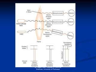
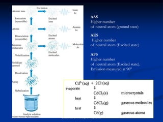
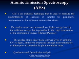
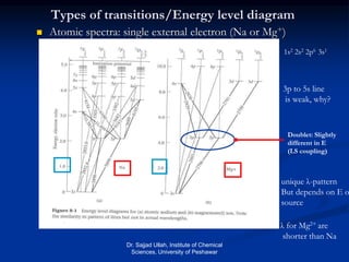
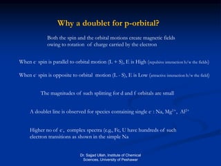
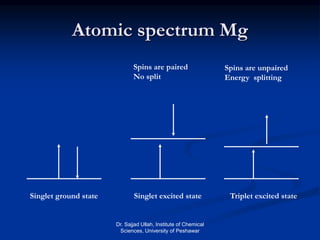
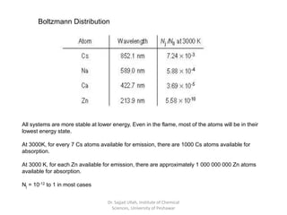
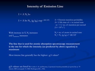
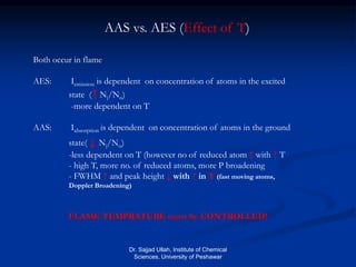
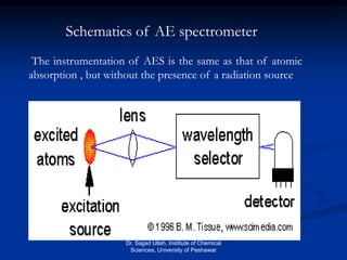
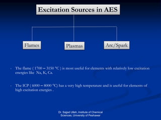
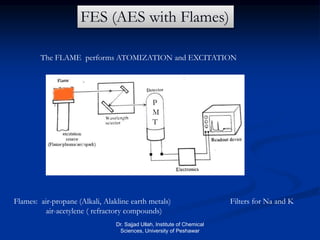
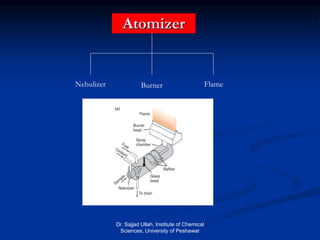
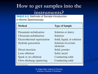
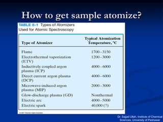
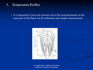
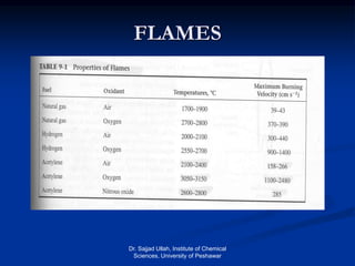
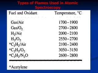
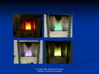
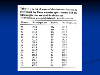
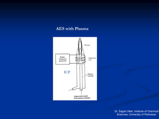
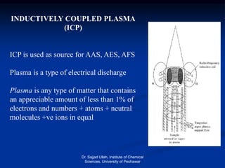
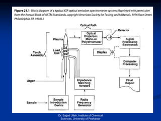
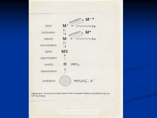
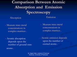
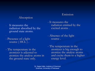

The document provides an overview of various atomic emission spectroscopy techniques such as flame emission spectroscopy and atomic fluorescence spectroscopy, emphasizing the principles and methodologies of atomic emission spectroscopy (AES) and atomic absorption spectroscopy (AAS). It discusses factors like excitation sources, instrumentation, and temperature effects on atomic transitions and emission lines. Additionally, it covers the use of inductively coupled plasma (ICP) as a high-sensitivity source for elemental analysis in comparison to traditional flame methods.


