Downloaded 569 times

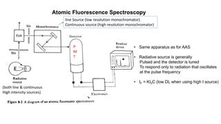
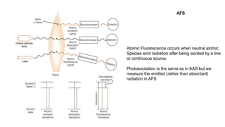
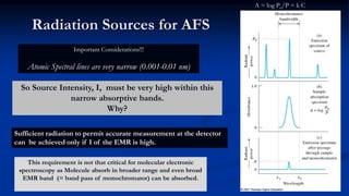
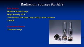
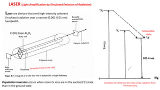
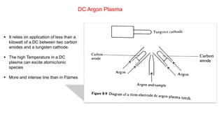
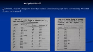
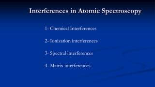
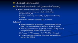
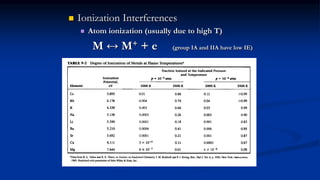
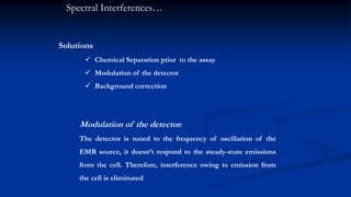
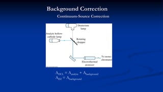
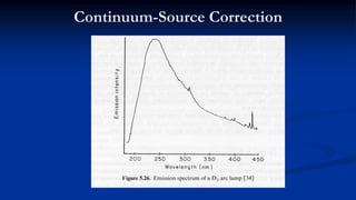


Atomic fluorescence spectroscopy uses the same apparatus as atomic absorption spectroscopy but measures the emitted radiation from excited atomic species rather than absorbed radiation. It can determine the concentration of elements present using either line sources like lasers or hollow cathode lamps, or continuous sources like xenon arc lamps. Interferences can occur from chemical reactions interfering with atomization, ionization of analytes, overlapping spectra from other elements or molecules, and background emission or scattering. These issues can be addressed through techniques like chemical separation, modulation of the detector, and background correction methods.


