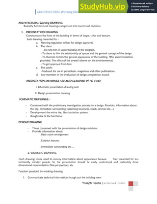
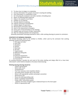
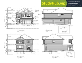
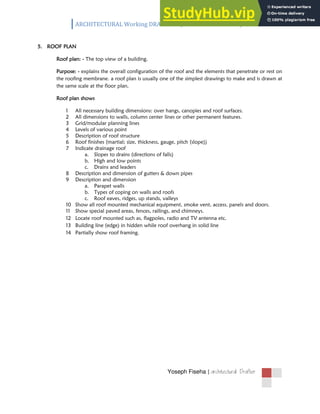
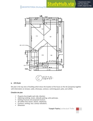
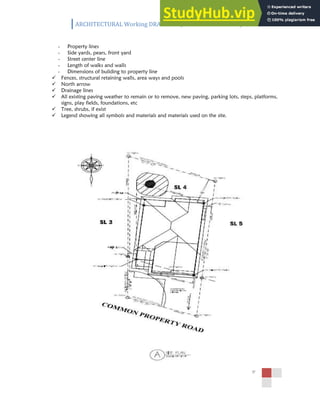
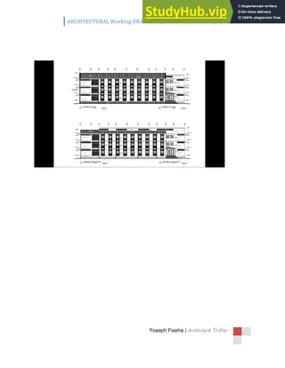
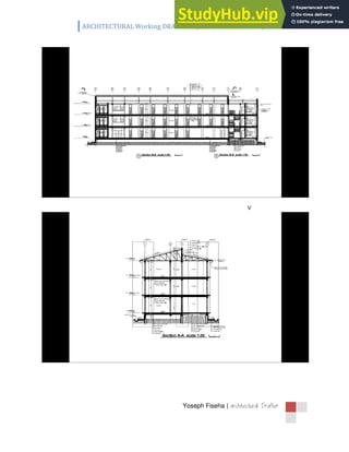
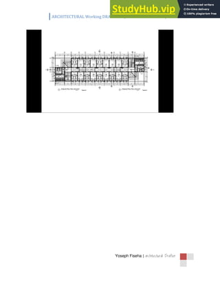
SlideShare a Scribd company logo
f01
by Yoseph.F
(Architectural Drafter)
ARCHITECTURAL Working DRAWING /Information handout/
Yoseph Fiseha | 
ARCHITECTURAL Working DRAWING
Basically Architectural drawings categorized into two broad divisions.
1. PRESENTATION DRAWING
Communicate the form of the building in terms of shape, color and texture.
Such drawing presented to: -
a. Planning regulation offices for design approval.
b. The client
-To help him in understanding of the program.
- To show to him the relationship of spaces and the general concept of the design.
- To illustrate to him the general appearance of the building. (The accommodation
provided. The effect of the overall scheme on the environmental)
- To get approval from him
c. The public
-Produced for use in periodicals, magazines and other publications.
d. Jury members in the evaluation of design competition award.
PRESENTATION DRAWINGS ARE ALSO CLASSIFIED IN TO TWO:
I. Schematic presentation drawing and
II. Design presentation drawing
SCHEMATIC DRAWINGS: -
- Concerned with the preliminary investigation process for a design. Provides, information about:
the site, immediate surrounding (adjoining structures, roads, services etc…)
- Development the entire site, like circulation pattern.
- Rough idea of the functional
DESIGNE DRAWING
- Those concerned with the presentation of design solutions.
- Provide information about:
. Basic room arrangement
. Exterior features
. Immediate surrounding etc …
2. WORKING DRAWING
-Such drawings more need to convey information about appearance because they presented for less
technically minded people. So the presentation should be easily understood and preferably three
dimensional representation (like-perspective), etc
Function provided by working drawing
1. Communicate technical information though out the building team
ARCHITECTURAL Working DRAWING /Information handout/
Yoseph Fiseha | 
2. To show how to design is to materialize
3. Convey information’s for people concerned in erecting the building
4. Give information’s to specification writer
5. for instructing the contractors and other members of building team
6. Means of obtaining official approval.
7. Helps in the analysis of cost factor.
8. Establish use of materials.
9. Provides detail for tendering.
10. Indicate contractual committeemen
11. Indicate degree of supervision.
12. Demonstrate construction details.
13. Assist in the measurement of progress.
14. Forms parts of documentation in site meetings.
15. Establish type and amount of labor requirement.
16. Basic for ordering materials and components.
Generally presentation drawings presented to client, while working drawings to present to contractors.
CONTENTS OF WORKING DRAWING
The finished drawings made by the architect or Drafter, which used by the contractor that working
drawings includes the following sheets.
1. Title page and index
2. Floor plan
3. Elevations
4. Sections
5. Roof plan
6. Site plan
7. Typical details
8. Reflected ceiling plan
9. Schedules
10. Electrical requirement
11. Plumbing (sanitarian plan)
12. Structural etc.
As working drawing is actually the end result of the entire drafting and design effort let us have basic
information’s which shall be included on the above listed drawings.
Working drawing drawings should be:
- Clearly representative
- Easily under stood
- Comprehensive
- Free from necessary notes (repetitive details )
- Accurately drawn (proper also in line work)
- Drawn with appropriate symbols and proper convention
- Dimensional well
- Drawn by referring building code
- Proper in graphical representation
- Proper titled (information panel)
- Logically and rarely arranged to give a balanced layout on the short paper
- Drawn in appropriate scale
ARCHITECTURAL Working DRAWING /Information handout/
Yoseph Fiseha | 
1. FLOOR PLAN
The floor plan is the heart of architectural drawings and is usually drawn first in professional plans. It is the
plan to which all trades people refer. It is a top view horizontal section cut through the house about 1.00 –
1.50cm above the floor. The purpose of the floor plan is to show the location and dimensions of exterior
and interior walls, windows, doors, major appliances, cabinets, fireplaces, and other fixed features in the
house.
Upon completion of the preliminary sketches and proposal, a 1:50 – 1:100 scale floor plan is drawn which
is considerably more detailed than previous floor plans. Windows and doors are coded. All exterior walls,
interior walls, windows, and doors are dimensioned. To conserve time and paper, the electrical plan is
sometimes included on the floor plan. On more complex plans, the electrical plan, the heating/cooling
plan, and the plumbing plan are drawn separately.
You will have one drawing for the floor plan, and one for the electrical.
A. Certain information is required on the floor plan:
 Exterior and interior walls
 Size and location of windows and doors
 Permanent fixtures, stairs, and fireplaces
 Sidewalks, patios and decks
 Room names and material symbols
 Location and size dimensions
 Scale of the drawing
B. When applicable, related structures such as freestanding garages or swimming pools
are shown on the floor plan
C. Walls should be drawn accurately. Exterior walls can be either 15cm or 20cm thick,
and interior walls should be 15cm thick. If you are using a brick veneer on the exterior
of the house, add 1” air space and an additional 3‐3/4” for the brick.
D. Fireplaces or stairs require only basic size and location information on the floor plan.
(Special details will be included in the plans for these features.).
E. Floor plans should include several dimensions. Each wall is dimensioned from its
center architectural dimensions should be in chain fashion or continuous and tics should be
used
2. FOUNDATION PLAN
After finishing the floor plan, the same scale foundation plan is drawn. All students will draw a basement
foundation. The weight of a house is supported by footings extended into the ground. These footings are
concrete with steel reinforcing to reduce cracking. The footings must extend below the frost line. All this
information should be given in the foundation plan
A. The foundation plan is a plan view in sections, which shows the location and size of footings,
piers, columns, foundation walls, and supporting beams. It is usually drawn after the floor plan
and elevations have been roughed out.
B. A foundation plan contains: Footings (hidden lines) Foundation walls Piers and columns Dwarf
walls (low walls to retain excavation or an embankment) Partition walls, doors, and bath fixtures
(if the house has a basement) Openings in the foundation walls (doors, windows, and vents)
Beams and pilasters Direction, size, spacing of floor joists, drains, and sump (if required) Details of
the foundation and footing construction. Complete dimensions and notes scale of the drawing.
C. Foundation information should be presented using the proper symbology.
ARCHITECTURAL Working DRAWING /Information handout/
Yoseph Fiseha | 
3. ELEVATIONS
An elevation is an orthographic drawing of the sides of the structure. The term “elevation" usually refers to
an outside elevation
Various interior elevations are included in a set of plans (kitchen, bathroom, etc.), but these are referred to
as details. The purpose of an elevation is to show the finished appearance of the structure and vertical
height dimensions. Four Elevations are usually drawn, one for each of the sides of the house.
A. Required Information
Identification of the specific side of the house elevation
Grade line
Finish floor and ceiling levels (shown with phantom lines)
Windows and doors
Foundation (shown with hidden lines)
Vertical dimensions of important features
Porches, desks, patios, and material symbols
B. Elevation Identification
Each elevation must be identified. Two commonly used methods are (Front, Rear, Right
Side, and Left Side), or (North, South, East, and West). The first method is the preferred.
Right and left sides are determined by facing the front of the building. Identify each
elevation directly below the drawing to avoid confusion.
C. Grade Lines, Floor and Ceilings
1. The reference point for most elevations is the grade line. All features that are below the
grade line should be shown as hidden lines. Examples are foundation, footings and
window wells.
2. Floor to ceiling height should be shown. Two method are used:
a. Finished floor to finished ceiling distances. The typical distance from finished floor
to finished ceiling is 2.80m – 3.00m.
b. The construction dimension or distance is from the top of the sub‐floor to the top
of the wall plate. In this case the construction dimension for the first floor is 8'‐1
1/8".
Sometimes second floors are 7'‐7 1/8". Carpenters prefer this method because it
saves them doing the calculations.
c. The top of the foundation must be 8" above the grade to protect framing members
from moisture.
d. Garage floors may be slightly higher than grade but should be at least 4" lower
than an interior when the garage is attached to the house.
D. Walls, Windows, Doors
1. Exterior walls, windows, and doors must be shown on elevations.
2. It is customary to make top of windows the same height as top of doors.
3. Usual door height is 6'‐ 8" from the top of the sub‐floor to the lower face of the head jam.
4. Windows and doors should receive DETAILED presentation on elevations.
E. Roof Features
1. Roof style, pitch, chimney height, and chimney size are shown.
2. The roof pitch may be indicated using the fractional pitch or slope triangle.
3. Chimney height above the highest point should be dimensioned and is usually 2’‐0" above the
ridge.
4. Chimney flashings, roof covering material, and gable ventilation area shown.
F. Dimensions, Notes, and Symbols
1. Vertical height dimensions are shown including:
a. footing thickness
b. distance from footing to grade
ARCHITECTURAL Working DRAWING /Information handout/
Yoseph Fiseha | 
c. finished floor to finished ceiling
d. overhang width
e. height of top of windows and doors
f. height of chimney above roof
2. Appropriate notes should be included where needed:
a. grade information
b. exterior wall material notation
c. roof covering material notation
d. fascia and flashing material
3. Symbols should be appropriately shown
a. roof pitch symbol
b. exterior wall material symbols
c. window
d. swing symbols (if needed)
4. SECTIONS
Section drawing is an orthographic projection that has been cut apart to show interior features.
PURPOSE
1. Describe the construction materials of the structure.
2. Describe method of construction. (General assembly of different parts)
3. Show interior design elements
4. Clearly depict the structural conditions existing in the building.
Generally, sectional drawings describe constructions materials and methods especially those things
hidden by wall or ceiling sheathing and are often the easiest way to describe a complex detail to a
contractor.
TYPES OF SECTIONS
1. STRUCTURAL SECTION
A structural section shows the entire building construction and also shows the interior spaces in
elevation.
a. BUILDING LONGUTIDNAL SECTION
Section takes on the long axis of the building
b. BUILDING CROSS-SECTION
Section taken across its narrower dimension.
2. WALL SECTION
Shows the construction of a typical wall to a larger scale than the structural section
3. DETAIL SECTION
Section views cut through a small segment of a building and drawn with enlarged scale
This are some of part are drawn in detail drawing
A. Window and door section
B. Stair section
C. Chimney section
D. Structural detail section
Sectional drawings are drawn in a scale of 1:50 or 1:100 in common working drawing but detail
section drawing are drawn in a scale 1:20 or 1:25 package. Sections are basically drawn referenced on plans
and elevations.
PLACEMENT OF CUTTING PLANE
The cutting plane best to be passes through;
 Stairs to show vertical movement
 Window and door to show detail in opening
 Important interior spaces to show the interior spaces well
Generally - depends on the need to convey the greatest amount of information and clarity for those
building structures.
ARCHITECTURAL Working DRAWING /Information handout/
Yoseph Fiseha | 
NUMBER OF SECTIONS TAKEN
The number required varies according to the structural complicity of the particular building.
Note: - Before drawing section drawing we should first gather basic information including
 Type of foundation
 Floor system
 Exterior and interior wall construction
 Beam and column sizes and their materials
 Wall height
 Floor elevation
 Floor members (sizes/ spacing)
 Floor sheathing material and size
 Ceiling size members /spacing
 Roof pitch
 Roof sheathing material and size
 Roof material
After having this information it is easy to draw sectional drawing by projecting from floor plan drawing
Check list for drawing section
1. Grid /modular section lines
2. Existing and new finished ground floor levels
3. Dimensions
A. External: -
i. Changes of direction, openings etc.
ii. over all of a building
B. Internal:-
i. Door and window openings, stair cases, ducts built in furniture, guard rails etc.
ii. room height /floor to floor
- Floor to ceiling
- Floor to top of a wall
- Floor to top of beam, column etc
Foundation in Section Drawing
- Description and dimensions including compositions, size and stepping details
- Foundation walls - material
- Thickness
- Back filling
-DPC
- Holes for drainage etc
- Fill and hard core materials, thickness and layering.
Floor in section Drawing
ARCHITECTURAL Working DRAWING /Information handout/
Yoseph Fiseha | 
- Thickness, composition, hard core, reinforced slab screed, floor finish
- Intermediate floor construction / type, material, dimensions, fixing, ceiling etc /
Wall in section Drawing
Exterior / interior wall-type, materials, dimensions, fixing finishes.
- Door and door frames, window and window frames
- Dimensions and description (referenced to schedule)
ARCHITECTURAL Working DRAWING /Information handout/
Yoseph Fiseha | 
5. ROOF PLAN
Roof plan: - The top view of a building.
Purpose: - explains the overall configuration of the roof and the elements that penetrate or rest on
the roofing membrane. a roof plan is usually one of the simplest drawings to make and is drawn at
the same scale at the floor plan.
Roof plan shows
1 All necessary building dimensions: over hangs, canopies and roof surfaces.
2 All dimensions to walls, column center lines or other permanent features.
3 Grid/modular planning lines
4 Levels of various point
5 Description of roof structure
6 Roof finishes (martial; size, thickness, gauge, pitch (slope))
7 Indicate drainage roof
a. Slopes to drains (directions of falls)
b. High and low points
c. Drains and leaders
8 Description and dimension of gutters & down pipes
9 Description and dimension
a. Parapet walls
b. Types of coping on walls and roofs
c. Roof eaves, ridges, up stands, valleys
10 Show all roof mounted mechanical equipment, smoke vent, access, panels and doors.
11 Show special paved areas, fences, railings, and chimneys.
12 Locate roof mounted such as, flagpoles, radio and TV antenna etc.
13 Building line (edge) in hidden while roof overhang in solid line
14 Partially show roof framing.
ARCHITECTURAL Working DRAWING /Information handout/
Yoseph Fiseha | 
6. SITE PLAN
Site plan is the top view of building which shows the location of the house on the site (property) together
with information on terraces, walks, driveways, contours, swimming pool, patio, and utilities.
Checklist site plan
 Property lines-lengths each side, direction
 Adjoining building, streets, sidewalk parking, curbs parkways.
 Existing structures and proposed structure.
 All utilities lines (sewer, electric, telephone).
 Contours, existing, new: contour elevations.
 Dimension
ARCHITECTURAL Working DRAWING /Information handout/
Yoseph Fiseha | 
- Property lines
- Side yards, pears, front yard
- Street center line
- Length of walks and walls
- Dimensions of building to property line
 Fences, structural retaining walls, area ways and pools
 North arrow
 Drainage lines
 All existing paving weather to remain or to remove, new paving, parking lots, steps, platforms,
signs, play fields, foundations, etc
 Tree, shrubs, if exist
 Legend showing all symbols and materials and materials used on the site.
ARCHITECTURAL Working DRAWING /Information handout/
Yoseph Fiseha | 
ARCHITECTURAL Working DRAWING /Information handout/
Yoseph Fiseha | 
V
ARCHITECTURAL Working DRAWING /Information handout/
Yoseph Fiseha | 

More Related Content

What's hot

Archi cad step_by_step
Archi cad step_by_stepArchi cad step_by_step
Archi cad step_by_step
imaduddin91
 
Landscape architecture
Landscape architectureLandscape architecture
Landscape architecture
Sheau Hui Tan
 
William morris (1834 1896)
William morris (1834 1896)William morris (1834 1896)
William morris (1834 1896)
Prannay Dhingra
 
types of drawing
types of drawingtypes of drawing
types of drawing
FiQahh AmiNn
 
ALUMINUM COMPOSITE PANELS
ALUMINUM COMPOSITE PANELSALUMINUM COMPOSITE PANELS
ALUMINUM COMPOSITE PANELS
ArchDuty
 
Emphasis : Principles of design
Emphasis : Principles of designEmphasis : Principles of design
Emphasis : Principles of design
Niranjana Madan
 
"Form and function are one" - Frank Lloyd Wright
"Form and function are one" - Frank Lloyd Wright"Form and function are one" - Frank Lloyd Wright
"Form and function are one" - Frank Lloyd Wright
Pranavi Nandagiri
 
Anatomy of architectural design concept
Anatomy of architectural design conceptAnatomy of architectural design concept
Anatomy of architectural design concept
Nahedh Al-Qemaqchi
 
Interior design styles 1
Interior design styles 1Interior design styles 1
Interior design styles 1
Haf Bedagh
 
Architectural concepts
Architectural conceptsArchitectural concepts
Architectural concepts
Aysheh Alshdaifat
 
08 - Portal Frame.pptx
08 - Portal Frame.pptx08 - Portal Frame.pptx
08 - Portal Frame.pptx
2022786965
 
Landscape Drawing
Landscape DrawingLandscape Drawing
Landscape Drawing
WC Yan
 
Philosophies of le corbusier
Philosophies of  le corbusierPhilosophies of  le corbusier
Philosophies of le corbusier
Manish Jain Luhadia
 
Wooden partition & wall paneling
Wooden partition & wall paneling Wooden partition & wall paneling
Wooden partition & wall paneling
vaibhav ghodke
 
Furniture timeline assignment
Furniture timeline assignmentFurniture timeline assignment
Furniture timeline assignment
jillainedawn
 
ARCHITECTURAL TERMS 1
ARCHITECTURAL TERMS 1ARCHITECTURAL TERMS 1
ARCHITECTURAL TERMS 1
Abhishek Mewada
 
false ceiling
false ceilingfalse ceiling
false ceiling
Manojnegi9777
 
ARCHITECTURAL TERMS 3
ARCHITECTURAL TERMS 3ARCHITECTURAL TERMS 3
ARCHITECTURAL TERMS 3
Abhishek Mewada
 
Drafting techniques in Building Materials and Construction
Drafting techniques in Building Materials and ConstructionDrafting techniques in Building Materials and Construction
Drafting techniques in Building Materials and Construction
Geeva Chandana
 
Moodboards For Interior Design
Moodboards For Interior DesignMoodboards For Interior Design
Moodboards For Interior Design
krztyn
 

What's hot (20)

Archi cad step_by_step
Archi cad step_by_stepArchi cad step_by_step
Archi cad step_by_step
 
Landscape architecture
Landscape architectureLandscape architecture
Landscape architecture
 
William morris (1834 1896)
William morris (1834 1896)William morris (1834 1896)
William morris (1834 1896)
 
types of drawing
types of drawingtypes of drawing
types of drawing
 
ALUMINUM COMPOSITE PANELS
ALUMINUM COMPOSITE PANELSALUMINUM COMPOSITE PANELS
ALUMINUM COMPOSITE PANELS
 
Emphasis : Principles of design
Emphasis : Principles of designEmphasis : Principles of design
Emphasis : Principles of design
 
"Form and function are one" - Frank Lloyd Wright
"Form and function are one" - Frank Lloyd Wright"Form and function are one" - Frank Lloyd Wright
"Form and function are one" - Frank Lloyd Wright
 
Anatomy of architectural design concept
Anatomy of architectural design conceptAnatomy of architectural design concept
Anatomy of architectural design concept
 
Interior design styles 1
Interior design styles 1Interior design styles 1
Interior design styles 1
 
Architectural concepts
Architectural conceptsArchitectural concepts
Architectural concepts
 
08 - Portal Frame.pptx
08 - Portal Frame.pptx08 - Portal Frame.pptx
08 - Portal Frame.pptx
 
Landscape Drawing
Landscape DrawingLandscape Drawing
Landscape Drawing
 
Philosophies of le corbusier
Philosophies of  le corbusierPhilosophies of  le corbusier
Philosophies of le corbusier
 
Wooden partition & wall paneling
Wooden partition & wall paneling Wooden partition & wall paneling
Wooden partition & wall paneling
 
Furniture timeline assignment
Furniture timeline assignmentFurniture timeline assignment
Furniture timeline assignment
 
ARCHITECTURAL TERMS 1
ARCHITECTURAL TERMS 1ARCHITECTURAL TERMS 1
ARCHITECTURAL TERMS 1
 
false ceiling
false ceilingfalse ceiling
false ceiling
 
ARCHITECTURAL TERMS 3
ARCHITECTURAL TERMS 3ARCHITECTURAL TERMS 3
ARCHITECTURAL TERMS 3
 
Drafting techniques in Building Materials and Construction
Drafting techniques in Building Materials and ConstructionDrafting techniques in Building Materials and Construction
Drafting techniques in Building Materials and Construction
 
Moodboards For Interior Design
Moodboards For Interior DesignMoodboards For Interior Design
Moodboards For Interior Design
 

Similar to ARCHITECTURAL Working DRAWING Information Handout

Building Drawing(CE3G)- Introduction.ppt
Building Drawing(CE3G)-  Introduction.pptBuilding Drawing(CE3G)-  Introduction.ppt
Building Drawing(CE3G)- Introduction.ppt
RameshMahato19
 
building construction
building constructionbuilding construction
building construction
Omar Gaheyr
 
Presentation (4).pptx
Presentation (4).pptxPresentation (4).pptx
Presentation (4).pptx
SatyaNarayana135764
 
Types of drawings
Types of drawingsTypes of drawings
Types of drawings
kevin porter
 
civil engineering drawing
civil engineering drawing civil engineering drawing
civil engineering drawing
Ahmad Hassan
 
Week 9 class notes
Week 9   class notesWeek 9   class notes
Week 9 class notes
Hans van Wees
 
Architectural Drawing
Architectural DrawingArchitectural Drawing
Architectural Drawing
Lea Alberto
 
Carpentry 7. Interpreting Technical Drawings and Plans.pptx
Carpentry 7. Interpreting Technical Drawings and Plans.pptxCarpentry 7. Interpreting Technical Drawings and Plans.pptx
Carpentry 7. Interpreting Technical Drawings and Plans.pptx
EDMARKPONCE2
 
Q3 e SIM WEEK 5-TECH.DRAFTING 10.pdf
Q3 e SIM WEEK 5-TECH.DRAFTING 10.pdfQ3 e SIM WEEK 5-TECH.DRAFTING 10.pdf
Q3 e SIM WEEK 5-TECH.DRAFTING 10.pdf
FloranteFerrer3
 
Section Working Drawing
Section Working DrawingSection Working Drawing
Section Working Drawing
Weam Adam
 
Designing & drawing elevations
Designing & drawing elevationsDesigning & drawing elevations
Designing & drawing elevations
Shabir Ahmad
 
Architectural working drawing
Architectural working drawingArchitectural working drawing
Architectural working drawing
Sanjib Sengupta
 
SURVEY.pdf
SURVEY.pdfSURVEY.pdf
SURVEY.pdf
AbenezerGetachew11
 
DRAWINGS & SYMBOL FOR THE ENGINEERING PROJECT-IR ASSRUL.pdf
DRAWINGS & SYMBOL FOR THE ENGINEERING PROJECT-IR ASSRUL.pdfDRAWINGS & SYMBOL FOR THE ENGINEERING PROJECT-IR ASSRUL.pdf
DRAWINGS & SYMBOL FOR THE ENGINEERING PROJECT-IR ASSRUL.pdf
Assrul Reedza Zulkifli
 
Civilenggdrawing
CivilenggdrawingCivilenggdrawing
Civilenggdrawing
mohammad moinuddin
 
Civil drawing detail
Civil drawing detailCivil drawing detail
Civil drawing detail
CADmantra Technologies
 
Module 3 module 1 architecural layout & details
Module 3   module 1 architecural layout & detailsModule 3   module 1 architecural layout & details
Module 3 module 1 architecural layout & details
Gilbert Bautista
 
Introduction to drawing
Introduction to drawingIntroduction to drawing
Introduction to drawing
Teoh Sze Ming
 
Introduction to drawing
Introduction to drawingIntroduction to drawing
Introduction to drawing
j3frin30
 
Scale drawings
Scale drawingsScale drawings
Scale drawings
Steve Jarvis
 

Similar to ARCHITECTURAL Working DRAWING Information Handout (20)

Building Drawing(CE3G)- Introduction.ppt
Building Drawing(CE3G)-  Introduction.pptBuilding Drawing(CE3G)-  Introduction.ppt
Building Drawing(CE3G)- Introduction.ppt
 
building construction
building constructionbuilding construction
building construction
 
Presentation (4).pptx
Presentation (4).pptxPresentation (4).pptx
Presentation (4).pptx
 
Types of drawings
Types of drawingsTypes of drawings
Types of drawings
 
civil engineering drawing
civil engineering drawing civil engineering drawing
civil engineering drawing
 
Week 9 class notes
Week 9   class notesWeek 9   class notes
Week 9 class notes
 
Architectural Drawing
Architectural DrawingArchitectural Drawing
Architectural Drawing
 
Carpentry 7. Interpreting Technical Drawings and Plans.pptx
Carpentry 7. Interpreting Technical Drawings and Plans.pptxCarpentry 7. Interpreting Technical Drawings and Plans.pptx
Carpentry 7. Interpreting Technical Drawings and Plans.pptx
 
Q3 e SIM WEEK 5-TECH.DRAFTING 10.pdf
Q3 e SIM WEEK 5-TECH.DRAFTING 10.pdfQ3 e SIM WEEK 5-TECH.DRAFTING 10.pdf
Q3 e SIM WEEK 5-TECH.DRAFTING 10.pdf
 
Section Working Drawing
Section Working DrawingSection Working Drawing
Section Working Drawing
 
Designing & drawing elevations
Designing & drawing elevationsDesigning & drawing elevations
Designing & drawing elevations
 
Architectural working drawing
Architectural working drawingArchitectural working drawing
Architectural working drawing
 
SURVEY.pdf
SURVEY.pdfSURVEY.pdf
SURVEY.pdf
 
DRAWINGS & SYMBOL FOR THE ENGINEERING PROJECT-IR ASSRUL.pdf
DRAWINGS & SYMBOL FOR THE ENGINEERING PROJECT-IR ASSRUL.pdfDRAWINGS & SYMBOL FOR THE ENGINEERING PROJECT-IR ASSRUL.pdf
DRAWINGS & SYMBOL FOR THE ENGINEERING PROJECT-IR ASSRUL.pdf
 
Civilenggdrawing
CivilenggdrawingCivilenggdrawing
Civilenggdrawing
 
Civil drawing detail
Civil drawing detailCivil drawing detail
Civil drawing detail
 
Module 3 module 1 architecural layout & details
Module 3   module 1 architecural layout & detailsModule 3   module 1 architecural layout & details
Module 3 module 1 architecural layout & details
 
Introduction to drawing
Introduction to drawingIntroduction to drawing
Introduction to drawing
 
Introduction to drawing
Introduction to drawingIntroduction to drawing
Introduction to drawing
 
Scale drawings
Scale drawingsScale drawings
Scale drawings
 

More from Lori Head

Essay About College Experienc
Essay About College ExperiencEssay About College Experienc
Essay About College Experienc
Lori Head
 
Primary Handwriting Paper All Kids Network
Primary Handwriting Paper All Kids NetworkPrimary Handwriting Paper All Kids Network
Primary Handwriting Paper All Kids Network
Lori Head
 
College Essay The Best College Essays
College Essay The Best College EssaysCollege Essay The Best College Essays
College Essay The Best College Essays
Lori Head
 
Methodology For Research Paper Writing
Methodology For Research Paper WritingMethodology For Research Paper Writing
Methodology For Research Paper Writing
Lori Head
 
Write An A Essay In A Day. Essay Writing Help, Essa
Write An A Essay In A Day. Essay Writing Help, EssaWrite An A Essay In A Day. Essay Writing Help, Essa
Write An A Essay In A Day. Essay Writing Help, Essa
Lori Head
 
Best Custom Australia Essay Writing Help HelpWithAssignment.Com
Best Custom Australia Essay Writing Help HelpWithAssignment.ComBest Custom Australia Essay Writing Help HelpWithAssignment.Com
Best Custom Australia Essay Writing Help HelpWithAssignment.Com
Lori Head
 
College Admission Essay Samples - Essay Writing C
College Admission Essay Samples - Essay Writing CCollege Admission Essay Samples - Essay Writing C
College Admission Essay Samples - Essay Writing C
Lori Head
 
How To Focus An Essay Topic Essay Topics, Persu
How To Focus An Essay Topic Essay Topics, PersuHow To Focus An Essay Topic Essay Topics, Persu
How To Focus An Essay Topic Essay Topics, Persu
Lori Head
 
Self Introduction For College Students. Self Introduction
Self Introduction For College Students. Self IntroductionSelf Introduction For College Students. Self Introduction
Self Introduction For College Students. Self Introduction
Lori Head
 
Printable Christmas Writing Paper Paper With Christm
Printable Christmas Writing Paper Paper With ChristmPrintable Christmas Writing Paper Paper With Christm
Printable Christmas Writing Paper Paper With Christm
Lori Head
 
College Essay Examples - 9 In P
College Essay Examples - 9 In PCollege Essay Examples - 9 In P
College Essay Examples - 9 In P
Lori Head
 
Cause-Effect Essay Article - ESL Worksheet By Rsliouat
Cause-Effect Essay Article - ESL Worksheet By RsliouatCause-Effect Essay Article - ESL Worksheet By Rsliouat
Cause-Effect Essay Article - ESL Worksheet By Rsliouat
Lori Head
 
MUN Position Paper Vietnam
MUN Position Paper VietnamMUN Position Paper Vietnam
MUN Position Paper Vietnam
Lori Head
 
Cause And Effect Essay Examples YourDictionary
Cause And Effect Essay Examples YourDictionaryCause And Effect Essay Examples YourDictionary
Cause And Effect Essay Examples YourDictionary
Lori Head
 
Premium Vector Trace The Names Of Solar System Pla
Premium Vector Trace The Names Of Solar System PlaPremium Vector Trace The Names Of Solar System Pla
Premium Vector Trace The Names Of Solar System Pla
Lori Head
 
Online Nursing Essay Writing Service - Meganursingwriters
Online Nursing Essay Writing Service - MeganursingwritersOnline Nursing Essay Writing Service - Meganursingwriters
Online Nursing Essay Writing Service - Meganursingwriters
Lori Head
 
Worst College Essay Ever Written Or Ever W
Worst College Essay Ever Written Or Ever WWorst College Essay Ever Written Or Ever W
Worst College Essay Ever Written Or Ever W
Lori Head
 
How To Become A Better, Faster, And More Efficien
How To Become A Better, Faster, And More EfficienHow To Become A Better, Faster, And More Efficien
How To Become A Better, Faster, And More Efficien
Lori Head
 
More On Making A Living Off Of
More On Making A Living Off OfMore On Making A Living Off Of
More On Making A Living Off Of
Lori Head
 
School Essay Ielts Essay Topics
School Essay Ielts Essay TopicsSchool Essay Ielts Essay Topics
School Essay Ielts Essay Topics
Lori Head
 

More from Lori Head (20)

Essay About College Experienc
Essay About College ExperiencEssay About College Experienc
Essay About College Experienc
 
Primary Handwriting Paper All Kids Network
Primary Handwriting Paper All Kids NetworkPrimary Handwriting Paper All Kids Network
Primary Handwriting Paper All Kids Network
 
College Essay The Best College Essays
College Essay The Best College EssaysCollege Essay The Best College Essays
College Essay The Best College Essays
 
Methodology For Research Paper Writing
Methodology For Research Paper WritingMethodology For Research Paper Writing
Methodology For Research Paper Writing
 
Write An A Essay In A Day. Essay Writing Help, Essa
Write An A Essay In A Day. Essay Writing Help, EssaWrite An A Essay In A Day. Essay Writing Help, Essa
Write An A Essay In A Day. Essay Writing Help, Essa
 
Best Custom Australia Essay Writing Help HelpWithAssignment.Com
Best Custom Australia Essay Writing Help HelpWithAssignment.ComBest Custom Australia Essay Writing Help HelpWithAssignment.Com
Best Custom Australia Essay Writing Help HelpWithAssignment.Com
 
College Admission Essay Samples - Essay Writing C
College Admission Essay Samples - Essay Writing CCollege Admission Essay Samples - Essay Writing C
College Admission Essay Samples - Essay Writing C
 
How To Focus An Essay Topic Essay Topics, Persu
How To Focus An Essay Topic Essay Topics, PersuHow To Focus An Essay Topic Essay Topics, Persu
How To Focus An Essay Topic Essay Topics, Persu
 
Self Introduction For College Students. Self Introduction
Self Introduction For College Students. Self IntroductionSelf Introduction For College Students. Self Introduction
Self Introduction For College Students. Self Introduction
 
Printable Christmas Writing Paper Paper With Christm
Printable Christmas Writing Paper Paper With ChristmPrintable Christmas Writing Paper Paper With Christm
Printable Christmas Writing Paper Paper With Christm
 
College Essay Examples - 9 In P
College Essay Examples - 9 In PCollege Essay Examples - 9 In P
College Essay Examples - 9 In P
 
Cause-Effect Essay Article - ESL Worksheet By Rsliouat
Cause-Effect Essay Article - ESL Worksheet By RsliouatCause-Effect Essay Article - ESL Worksheet By Rsliouat
Cause-Effect Essay Article - ESL Worksheet By Rsliouat
 
MUN Position Paper Vietnam
MUN Position Paper VietnamMUN Position Paper Vietnam
MUN Position Paper Vietnam
 
Cause And Effect Essay Examples YourDictionary
Cause And Effect Essay Examples YourDictionaryCause And Effect Essay Examples YourDictionary
Cause And Effect Essay Examples YourDictionary
 
Premium Vector Trace The Names Of Solar System Pla
Premium Vector Trace The Names Of Solar System PlaPremium Vector Trace The Names Of Solar System Pla
Premium Vector Trace The Names Of Solar System Pla
 
Online Nursing Essay Writing Service - Meganursingwriters
Online Nursing Essay Writing Service - MeganursingwritersOnline Nursing Essay Writing Service - Meganursingwriters
Online Nursing Essay Writing Service - Meganursingwriters
 
Worst College Essay Ever Written Or Ever W
Worst College Essay Ever Written Or Ever WWorst College Essay Ever Written Or Ever W
Worst College Essay Ever Written Or Ever W
 
How To Become A Better, Faster, And More Efficien
How To Become A Better, Faster, And More EfficienHow To Become A Better, Faster, And More Efficien
How To Become A Better, Faster, And More Efficien
 
More On Making A Living Off Of
More On Making A Living Off OfMore On Making A Living Off Of
More On Making A Living Off Of
 
School Essay Ielts Essay Topics
School Essay Ielts Essay TopicsSchool Essay Ielts Essay Topics
School Essay Ielts Essay Topics
 

Recently uploaded

The basics of sentences session 6pptx.pptx
The basics of sentences session 6pptx.pptxThe basics of sentences session 6pptx.pptx
The basics of sentences session 6pptx.pptx
heathfieldcps1
 
Film vocab for eal 3 students: Australia the movie
Film vocab for eal 3 students: Australia the movieFilm vocab for eal 3 students: Australia the movie
Film vocab for eal 3 students: Australia the movie
Nicholas Montgomery
 
The History of Stoke Newington Street Names
The History of Stoke Newington Street NamesThe History of Stoke Newington Street Names
The History of Stoke Newington Street Names
History of Stoke Newington
 
South African Journal of Science: Writing with integrity workshop (2024)
South African Journal of Science: Writing with integrity workshop (2024)South African Journal of Science: Writing with integrity workshop (2024)
South African Journal of Science: Writing with integrity workshop (2024)
Academy of Science of South Africa
 
CACJapan - GROUP Presentation 1- Wk 4.pdf
CACJapan - GROUP Presentation 1- Wk 4.pdfCACJapan - GROUP Presentation 1- Wk 4.pdf
CACJapan - GROUP Presentation 1- Wk 4.pdf
camakaiclarkmusic
 
The Diamonds of 2023-2024 in the IGRA collection
The Diamonds of 2023-2024 in the IGRA collectionThe Diamonds of 2023-2024 in the IGRA collection
The Diamonds of 2023-2024 in the IGRA collection
Israel Genealogy Research Association
 
Digital Artifact 1 - 10VCD Environments Unit
Digital Artifact 1 - 10VCD Environments UnitDigital Artifact 1 - 10VCD Environments Unit
Digital Artifact 1 - 10VCD Environments Unit
chanes7
 
Advanced Java[Extra Concepts, Not Difficult].docx
Advanced Java[Extra Concepts, Not Difficult].docxAdvanced Java[Extra Concepts, Not Difficult].docx
Advanced Java[Extra Concepts, Not Difficult].docx
adhitya5119
 
Lapbook sobre os Regimes Totalitários.pdf
Lapbook sobre os Regimes Totalitários.pdfLapbook sobre os Regimes Totalitários.pdf
Lapbook sobre os Regimes Totalitários.pdf
Jean Carlos Nunes Paixão
 
June 3, 2024 Anti-Semitism Letter Sent to MIT President Kornbluth and MIT Cor...
June 3, 2024 Anti-Semitism Letter Sent to MIT President Kornbluth and MIT Cor...June 3, 2024 Anti-Semitism Letter Sent to MIT President Kornbluth and MIT Cor...
June 3, 2024 Anti-Semitism Letter Sent to MIT President Kornbluth and MIT Cor...
Levi Shapiro
 
How to Fix the Import Error in the Odoo 17
How to Fix the Import Error in the Odoo 17How to Fix the Import Error in the Odoo 17
How to Fix the Import Error in the Odoo 17
Celine George
 
S1-Introduction-Biopesticides in ICM.pptx
S1-Introduction-Biopesticides in ICM.pptxS1-Introduction-Biopesticides in ICM.pptx
S1-Introduction-Biopesticides in ICM.pptx
tarandeep35
 
Azure Interview Questions and Answers PDF By ScholarHat
Azure Interview Questions and Answers PDF By ScholarHatAzure Interview Questions and Answers PDF By ScholarHat
Azure Interview Questions and Answers PDF By ScholarHat
Scholarhat
 
Pollock and Snow "DEIA in the Scholarly Landscape, Session One: Setting Expec...
Pollock and Snow "DEIA in the Scholarly Landscape, Session One: Setting Expec...Pollock and Snow "DEIA in the Scholarly Landscape, Session One: Setting Expec...
Pollock and Snow "DEIA in the Scholarly Landscape, Session One: Setting Expec...
National Information Standards Organization (NISO)
 
Executive Directors Chat Leveraging AI for Diversity, Equity, and Inclusion
Executive Directors Chat  Leveraging AI for Diversity, Equity, and InclusionExecutive Directors Chat  Leveraging AI for Diversity, Equity, and Inclusion
Executive Directors Chat Leveraging AI for Diversity, Equity, and Inclusion
TechSoup
 
MATATAG CURRICULUM: ASSESSING THE READINESS OF ELEM. PUBLIC SCHOOL TEACHERS I...
MATATAG CURRICULUM: ASSESSING THE READINESS OF ELEM. PUBLIC SCHOOL TEACHERS I...MATATAG CURRICULUM: ASSESSING THE READINESS OF ELEM. PUBLIC SCHOOL TEACHERS I...
MATATAG CURRICULUM: ASSESSING THE READINESS OF ELEM. PUBLIC SCHOOL TEACHERS I...
NelTorrente
 
ANATOMY AND BIOMECHANICS OF HIP JOINT.pdf
ANATOMY AND BIOMECHANICS OF HIP JOINT.pdfANATOMY AND BIOMECHANICS OF HIP JOINT.pdf
ANATOMY AND BIOMECHANICS OF HIP JOINT.pdf
Priyankaranawat4
 
Main Java[All of the Base Concepts}.docx
Main Java[All of the Base Concepts}.docxMain Java[All of the Base Concepts}.docx
Main Java[All of the Base Concepts}.docx
adhitya5119
 
PCOS corelations and management through Ayurveda.
PCOS corelations and management through Ayurveda.PCOS corelations and management through Ayurveda.
PCOS corelations and management through Ayurveda.
Dr. Shivangi Singh Parihar
 
Group Presentation 2 Economics.Ariana Buscigliopptx
Group Presentation 2 Economics.Ariana BuscigliopptxGroup Presentation 2 Economics.Ariana Buscigliopptx
Group Presentation 2 Economics.Ariana Buscigliopptx
ArianaBusciglio
 

Recently uploaded (20)

The basics of sentences session 6pptx.pptx
The basics of sentences session 6pptx.pptxThe basics of sentences session 6pptx.pptx
The basics of sentences session 6pptx.pptx
 
Film vocab for eal 3 students: Australia the movie
Film vocab for eal 3 students: Australia the movieFilm vocab for eal 3 students: Australia the movie
Film vocab for eal 3 students: Australia the movie
 
The History of Stoke Newington Street Names
The History of Stoke Newington Street NamesThe History of Stoke Newington Street Names
The History of Stoke Newington Street Names
 
South African Journal of Science: Writing with integrity workshop (2024)
South African Journal of Science: Writing with integrity workshop (2024)South African Journal of Science: Writing with integrity workshop (2024)
South African Journal of Science: Writing with integrity workshop (2024)
 
CACJapan - GROUP Presentation 1- Wk 4.pdf
CACJapan - GROUP Presentation 1- Wk 4.pdfCACJapan - GROUP Presentation 1- Wk 4.pdf
CACJapan - GROUP Presentation 1- Wk 4.pdf
 
The Diamonds of 2023-2024 in the IGRA collection
The Diamonds of 2023-2024 in the IGRA collectionThe Diamonds of 2023-2024 in the IGRA collection
The Diamonds of 2023-2024 in the IGRA collection
 
Digital Artifact 1 - 10VCD Environments Unit
Digital Artifact 1 - 10VCD Environments UnitDigital Artifact 1 - 10VCD Environments Unit
Digital Artifact 1 - 10VCD Environments Unit
 
Advanced Java[Extra Concepts, Not Difficult].docx
Advanced Java[Extra Concepts, Not Difficult].docxAdvanced Java[Extra Concepts, Not Difficult].docx
Advanced Java[Extra Concepts, Not Difficult].docx
 
Lapbook sobre os Regimes Totalitários.pdf
Lapbook sobre os Regimes Totalitários.pdfLapbook sobre os Regimes Totalitários.pdf
Lapbook sobre os Regimes Totalitários.pdf
 
June 3, 2024 Anti-Semitism Letter Sent to MIT President Kornbluth and MIT Cor...
June 3, 2024 Anti-Semitism Letter Sent to MIT President Kornbluth and MIT Cor...June 3, 2024 Anti-Semitism Letter Sent to MIT President Kornbluth and MIT Cor...
June 3, 2024 Anti-Semitism Letter Sent to MIT President Kornbluth and MIT Cor...
 
How to Fix the Import Error in the Odoo 17
How to Fix the Import Error in the Odoo 17How to Fix the Import Error in the Odoo 17
How to Fix the Import Error in the Odoo 17
 
S1-Introduction-Biopesticides in ICM.pptx
S1-Introduction-Biopesticides in ICM.pptxS1-Introduction-Biopesticides in ICM.pptx
S1-Introduction-Biopesticides in ICM.pptx
 
Azure Interview Questions and Answers PDF By ScholarHat
Azure Interview Questions and Answers PDF By ScholarHatAzure Interview Questions and Answers PDF By ScholarHat
Azure Interview Questions and Answers PDF By ScholarHat
 
Pollock and Snow "DEIA in the Scholarly Landscape, Session One: Setting Expec...
Pollock and Snow "DEIA in the Scholarly Landscape, Session One: Setting Expec...Pollock and Snow "DEIA in the Scholarly Landscape, Session One: Setting Expec...
Pollock and Snow "DEIA in the Scholarly Landscape, Session One: Setting Expec...
 
Executive Directors Chat Leveraging AI for Diversity, Equity, and Inclusion
Executive Directors Chat  Leveraging AI for Diversity, Equity, and InclusionExecutive Directors Chat  Leveraging AI for Diversity, Equity, and Inclusion
Executive Directors Chat Leveraging AI for Diversity, Equity, and Inclusion
 
MATATAG CURRICULUM: ASSESSING THE READINESS OF ELEM. PUBLIC SCHOOL TEACHERS I...
MATATAG CURRICULUM: ASSESSING THE READINESS OF ELEM. PUBLIC SCHOOL TEACHERS I...MATATAG CURRICULUM: ASSESSING THE READINESS OF ELEM. PUBLIC SCHOOL TEACHERS I...
MATATAG CURRICULUM: ASSESSING THE READINESS OF ELEM. PUBLIC SCHOOL TEACHERS I...
 
ANATOMY AND BIOMECHANICS OF HIP JOINT.pdf
ANATOMY AND BIOMECHANICS OF HIP JOINT.pdfANATOMY AND BIOMECHANICS OF HIP JOINT.pdf
ANATOMY AND BIOMECHANICS OF HIP JOINT.pdf
 
Main Java[All of the Base Concepts}.docx
Main Java[All of the Base Concepts}.docxMain Java[All of the Base Concepts}.docx
Main Java[All of the Base Concepts}.docx
 
PCOS corelations and management through Ayurveda.
PCOS corelations and management through Ayurveda.PCOS corelations and management through Ayurveda.
PCOS corelations and management through Ayurveda.
 
Group Presentation 2 Economics.Ariana Buscigliopptx
Group Presentation 2 Economics.Ariana BuscigliopptxGroup Presentation 2 Economics.Ariana Buscigliopptx
Group Presentation 2 Economics.Ariana Buscigliopptx
 

ARCHITECTURAL Working DRAWING Information Handout

  • 2. ARCHITECTURAL Working DRAWING /Information handout/ Yoseph Fiseha |  ARCHITECTURAL Working DRAWING Basically Architectural drawings categorized into two broad divisions. 1. PRESENTATION DRAWING Communicate the form of the building in terms of shape, color and texture. Such drawing presented to: - a. Planning regulation offices for design approval. b. The client -To help him in understanding of the program. - To show to him the relationship of spaces and the general concept of the design. - To illustrate to him the general appearance of the building. (The accommodation provided. The effect of the overall scheme on the environmental) - To get approval from him c. The public -Produced for use in periodicals, magazines and other publications. d. Jury members in the evaluation of design competition award. PRESENTATION DRAWINGS ARE ALSO CLASSIFIED IN TO TWO: I. Schematic presentation drawing and II. Design presentation drawing SCHEMATIC DRAWINGS: - - Concerned with the preliminary investigation process for a design. Provides, information about: the site, immediate surrounding (adjoining structures, roads, services etc…) - Development the entire site, like circulation pattern. - Rough idea of the functional DESIGNE DRAWING - Those concerned with the presentation of design solutions. - Provide information about: . Basic room arrangement . Exterior features . Immediate surrounding etc … 2. WORKING DRAWING -Such drawings more need to convey information about appearance because they presented for less technically minded people. So the presentation should be easily understood and preferably three dimensional representation (like-perspective), etc Function provided by working drawing 1. Communicate technical information though out the building team
  • 3. ARCHITECTURAL Working DRAWING /Information handout/ Yoseph Fiseha |  2. To show how to design is to materialize 3. Convey information’s for people concerned in erecting the building 4. Give information’s to specification writer 5. for instructing the contractors and other members of building team 6. Means of obtaining official approval. 7. Helps in the analysis of cost factor. 8. Establish use of materials. 9. Provides detail for tendering. 10. Indicate contractual committeemen 11. Indicate degree of supervision. 12. Demonstrate construction details. 13. Assist in the measurement of progress. 14. Forms parts of documentation in site meetings. 15. Establish type and amount of labor requirement. 16. Basic for ordering materials and components. Generally presentation drawings presented to client, while working drawings to present to contractors. CONTENTS OF WORKING DRAWING The finished drawings made by the architect or Drafter, which used by the contractor that working drawings includes the following sheets. 1. Title page and index 2. Floor plan 3. Elevations 4. Sections 5. Roof plan 6. Site plan 7. Typical details 8. Reflected ceiling plan 9. Schedules 10. Electrical requirement 11. Plumbing (sanitarian plan) 12. Structural etc. As working drawing is actually the end result of the entire drafting and design effort let us have basic information’s which shall be included on the above listed drawings. Working drawing drawings should be: - Clearly representative - Easily under stood - Comprehensive - Free from necessary notes (repetitive details ) - Accurately drawn (proper also in line work) - Drawn with appropriate symbols and proper convention - Dimensional well - Drawn by referring building code - Proper in graphical representation - Proper titled (information panel) - Logically and rarely arranged to give a balanced layout on the short paper - Drawn in appropriate scale
  • 4. ARCHITECTURAL Working DRAWING /Information handout/ Yoseph Fiseha |  1. FLOOR PLAN The floor plan is the heart of architectural drawings and is usually drawn first in professional plans. It is the plan to which all trades people refer. It is a top view horizontal section cut through the house about 1.00 – 1.50cm above the floor. The purpose of the floor plan is to show the location and dimensions of exterior and interior walls, windows, doors, major appliances, cabinets, fireplaces, and other fixed features in the house. Upon completion of the preliminary sketches and proposal, a 1:50 – 1:100 scale floor plan is drawn which is considerably more detailed than previous floor plans. Windows and doors are coded. All exterior walls, interior walls, windows, and doors are dimensioned. To conserve time and paper, the electrical plan is sometimes included on the floor plan. On more complex plans, the electrical plan, the heating/cooling plan, and the plumbing plan are drawn separately. You will have one drawing for the floor plan, and one for the electrical. A. Certain information is required on the floor plan:  Exterior and interior walls  Size and location of windows and doors  Permanent fixtures, stairs, and fireplaces  Sidewalks, patios and decks  Room names and material symbols  Location and size dimensions  Scale of the drawing B. When applicable, related structures such as freestanding garages or swimming pools are shown on the floor plan C. Walls should be drawn accurately. Exterior walls can be either 15cm or 20cm thick, and interior walls should be 15cm thick. If you are using a brick veneer on the exterior of the house, add 1” air space and an additional 3‐3/4” for the brick. D. Fireplaces or stairs require only basic size and location information on the floor plan. (Special details will be included in the plans for these features.). E. Floor plans should include several dimensions. Each wall is dimensioned from its center architectural dimensions should be in chain fashion or continuous and tics should be used
  • 5.
  • 6. 2. FOUNDATION PLAN After finishing the floor plan, the same scale foundation plan is drawn. All students will draw a basement foundation. The weight of a house is supported by footings extended into the ground. These footings are concrete with steel reinforcing to reduce cracking. The footings must extend below the frost line. All this information should be given in the foundation plan A. The foundation plan is a plan view in sections, which shows the location and size of footings, piers, columns, foundation walls, and supporting beams. It is usually drawn after the floor plan and elevations have been roughed out. B. A foundation plan contains: Footings (hidden lines) Foundation walls Piers and columns Dwarf walls (low walls to retain excavation or an embankment) Partition walls, doors, and bath fixtures (if the house has a basement) Openings in the foundation walls (doors, windows, and vents) Beams and pilasters Direction, size, spacing of floor joists, drains, and sump (if required) Details of the foundation and footing construction. Complete dimensions and notes scale of the drawing. C. Foundation information should be presented using the proper symbology.
  • 7. ARCHITECTURAL Working DRAWING /Information handout/ Yoseph Fiseha |  3. ELEVATIONS An elevation is an orthographic drawing of the sides of the structure. The term “elevation" usually refers to an outside elevation Various interior elevations are included in a set of plans (kitchen, bathroom, etc.), but these are referred to as details. The purpose of an elevation is to show the finished appearance of the structure and vertical height dimensions. Four Elevations are usually drawn, one for each of the sides of the house. A. Required Information Identification of the specific side of the house elevation Grade line Finish floor and ceiling levels (shown with phantom lines) Windows and doors Foundation (shown with hidden lines) Vertical dimensions of important features Porches, desks, patios, and material symbols B. Elevation Identification Each elevation must be identified. Two commonly used methods are (Front, Rear, Right Side, and Left Side), or (North, South, East, and West). The first method is the preferred. Right and left sides are determined by facing the front of the building. Identify each elevation directly below the drawing to avoid confusion. C. Grade Lines, Floor and Ceilings 1. The reference point for most elevations is the grade line. All features that are below the grade line should be shown as hidden lines. Examples are foundation, footings and window wells. 2. Floor to ceiling height should be shown. Two method are used: a. Finished floor to finished ceiling distances. The typical distance from finished floor to finished ceiling is 2.80m – 3.00m. b. The construction dimension or distance is from the top of the sub‐floor to the top of the wall plate. In this case the construction dimension for the first floor is 8'‐1 1/8". Sometimes second floors are 7'‐7 1/8". Carpenters prefer this method because it saves them doing the calculations. c. The top of the foundation must be 8" above the grade to protect framing members from moisture. d. Garage floors may be slightly higher than grade but should be at least 4" lower than an interior when the garage is attached to the house. D. Walls, Windows, Doors 1. Exterior walls, windows, and doors must be shown on elevations. 2. It is customary to make top of windows the same height as top of doors. 3. Usual door height is 6'‐ 8" from the top of the sub‐floor to the lower face of the head jam. 4. Windows and doors should receive DETAILED presentation on elevations. E. Roof Features 1. Roof style, pitch, chimney height, and chimney size are shown. 2. The roof pitch may be indicated using the fractional pitch or slope triangle. 3. Chimney height above the highest point should be dimensioned and is usually 2’‐0" above the ridge. 4. Chimney flashings, roof covering material, and gable ventilation area shown. F. Dimensions, Notes, and Symbols 1. Vertical height dimensions are shown including: a. footing thickness b. distance from footing to grade
  • 8. ARCHITECTURAL Working DRAWING /Information handout/ Yoseph Fiseha |  c. finished floor to finished ceiling d. overhang width e. height of top of windows and doors f. height of chimney above roof 2. Appropriate notes should be included where needed: a. grade information b. exterior wall material notation c. roof covering material notation d. fascia and flashing material 3. Symbols should be appropriately shown a. roof pitch symbol b. exterior wall material symbols c. window d. swing symbols (if needed)
  • 9.
  • 10. 4. SECTIONS Section drawing is an orthographic projection that has been cut apart to show interior features. PURPOSE 1. Describe the construction materials of the structure. 2. Describe method of construction. (General assembly of different parts) 3. Show interior design elements 4. Clearly depict the structural conditions existing in the building. Generally, sectional drawings describe constructions materials and methods especially those things hidden by wall or ceiling sheathing and are often the easiest way to describe a complex detail to a contractor. TYPES OF SECTIONS 1. STRUCTURAL SECTION A structural section shows the entire building construction and also shows the interior spaces in elevation. a. BUILDING LONGUTIDNAL SECTION Section takes on the long axis of the building b. BUILDING CROSS-SECTION Section taken across its narrower dimension. 2. WALL SECTION Shows the construction of a typical wall to a larger scale than the structural section 3. DETAIL SECTION Section views cut through a small segment of a building and drawn with enlarged scale This are some of part are drawn in detail drawing A. Window and door section B. Stair section C. Chimney section D. Structural detail section Sectional drawings are drawn in a scale of 1:50 or 1:100 in common working drawing but detail section drawing are drawn in a scale 1:20 or 1:25 package. Sections are basically drawn referenced on plans and elevations. PLACEMENT OF CUTTING PLANE The cutting plane best to be passes through;  Stairs to show vertical movement  Window and door to show detail in opening  Important interior spaces to show the interior spaces well Generally - depends on the need to convey the greatest amount of information and clarity for those building structures.
  • 11. ARCHITECTURAL Working DRAWING /Information handout/ Yoseph Fiseha |  NUMBER OF SECTIONS TAKEN The number required varies according to the structural complicity of the particular building. Note: - Before drawing section drawing we should first gather basic information including  Type of foundation  Floor system  Exterior and interior wall construction  Beam and column sizes and their materials  Wall height  Floor elevation  Floor members (sizes/ spacing)  Floor sheathing material and size  Ceiling size members /spacing  Roof pitch  Roof sheathing material and size  Roof material After having this information it is easy to draw sectional drawing by projecting from floor plan drawing Check list for drawing section 1. Grid /modular section lines 2. Existing and new finished ground floor levels 3. Dimensions A. External: - i. Changes of direction, openings etc. ii. over all of a building B. Internal:- i. Door and window openings, stair cases, ducts built in furniture, guard rails etc. ii. room height /floor to floor - Floor to ceiling - Floor to top of a wall - Floor to top of beam, column etc Foundation in Section Drawing - Description and dimensions including compositions, size and stepping details - Foundation walls - material - Thickness - Back filling -DPC - Holes for drainage etc - Fill and hard core materials, thickness and layering. Floor in section Drawing
  • 12. ARCHITECTURAL Working DRAWING /Information handout/ Yoseph Fiseha |  - Thickness, composition, hard core, reinforced slab screed, floor finish - Intermediate floor construction / type, material, dimensions, fixing, ceiling etc / Wall in section Drawing Exterior / interior wall-type, materials, dimensions, fixing finishes. - Door and door frames, window and window frames - Dimensions and description (referenced to schedule)
  • 13. ARCHITECTURAL Working DRAWING /Information handout/ Yoseph Fiseha |  5. ROOF PLAN Roof plan: - The top view of a building. Purpose: - explains the overall configuration of the roof and the elements that penetrate or rest on the roofing membrane. a roof plan is usually one of the simplest drawings to make and is drawn at the same scale at the floor plan. Roof plan shows 1 All necessary building dimensions: over hangs, canopies and roof surfaces. 2 All dimensions to walls, column center lines or other permanent features. 3 Grid/modular planning lines 4 Levels of various point 5 Description of roof structure 6 Roof finishes (martial; size, thickness, gauge, pitch (slope)) 7 Indicate drainage roof a. Slopes to drains (directions of falls) b. High and low points c. Drains and leaders 8 Description and dimension of gutters & down pipes 9 Description and dimension a. Parapet walls b. Types of coping on walls and roofs c. Roof eaves, ridges, up stands, valleys 10 Show all roof mounted mechanical equipment, smoke vent, access, panels and doors. 11 Show special paved areas, fences, railings, and chimneys. 12 Locate roof mounted such as, flagpoles, radio and TV antenna etc. 13 Building line (edge) in hidden while roof overhang in solid line 14 Partially show roof framing.
  • 14. ARCHITECTURAL Working DRAWING /Information handout/ Yoseph Fiseha |  6. SITE PLAN Site plan is the top view of building which shows the location of the house on the site (property) together with information on terraces, walks, driveways, contours, swimming pool, patio, and utilities. Checklist site plan  Property lines-lengths each side, direction  Adjoining building, streets, sidewalk parking, curbs parkways.  Existing structures and proposed structure.  All utilities lines (sewer, electric, telephone).  Contours, existing, new: contour elevations.  Dimension
  • 15. ARCHITECTURAL Working DRAWING /Information handout/ Yoseph Fiseha |  - Property lines - Side yards, pears, front yard - Street center line - Length of walks and walls - Dimensions of building to property line  Fences, structural retaining walls, area ways and pools  North arrow  Drainage lines  All existing paving weather to remain or to remove, new paving, parking lots, steps, platforms, signs, play fields, foundations, etc  Tree, shrubs, if exist  Legend showing all symbols and materials and materials used on the site.
  • 16. ARCHITECTURAL Working DRAWING /Information handout/ Yoseph Fiseha | 
  • 17. ARCHITECTURAL Working DRAWING /Information handout/ Yoseph Fiseha |  V
  • 18. ARCHITECTURAL Working DRAWING /Information handout/ Yoseph Fiseha | 