Downloaded 2,515 times

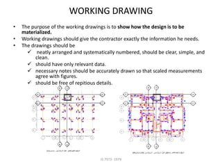
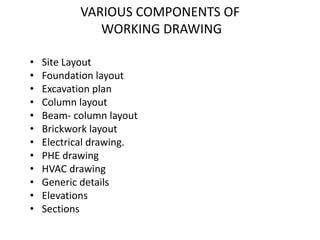
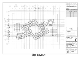
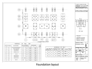
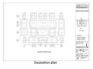
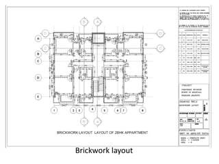
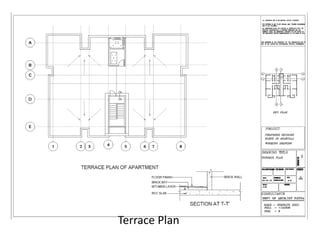
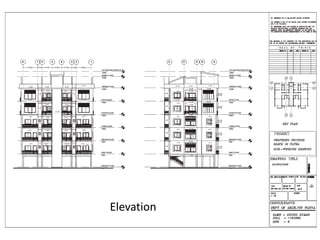


This document discusses the types and purposes of architectural drawings. It begins by defining drawings and their uses. It then describes the different types of architectural drawings, including concept sketches, survey drawings, presentation drawings, municipal drawings, working drawings, and record drawings. For each type of drawing, it provides a brief explanation of its purpose. It also discusses the components and standards of architectural drawings, such as site plans, floor plans, elevations, and sections. Overall, the document provides a high-level overview of the key types of drawings used in architectural design and construction projects.


