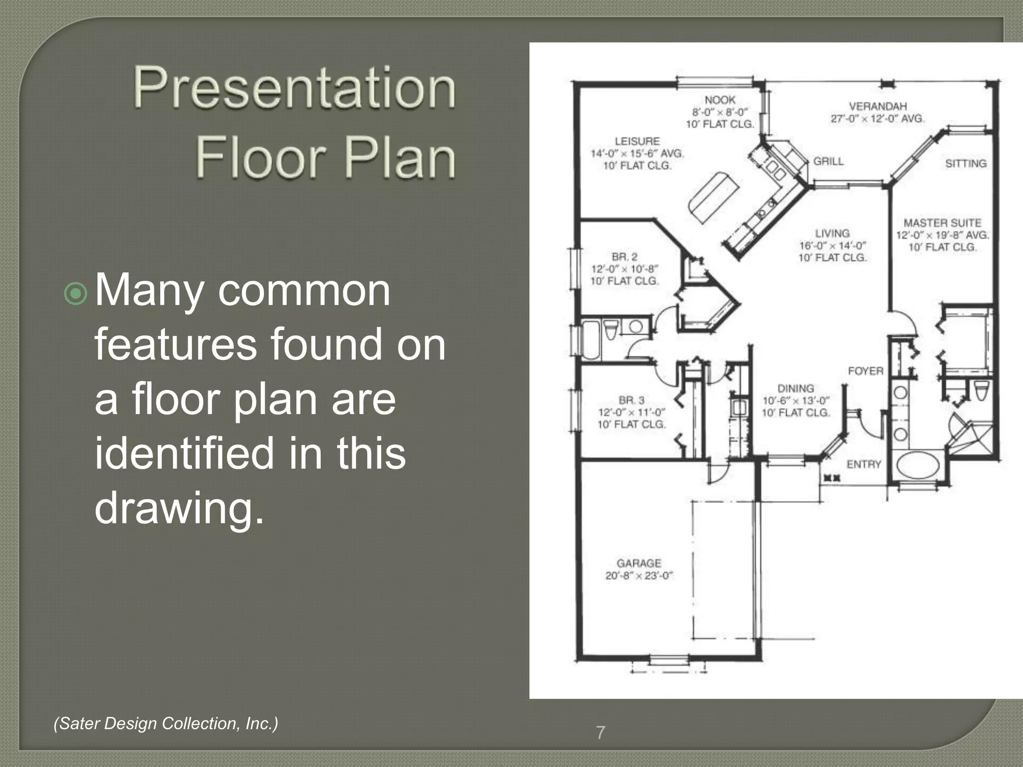
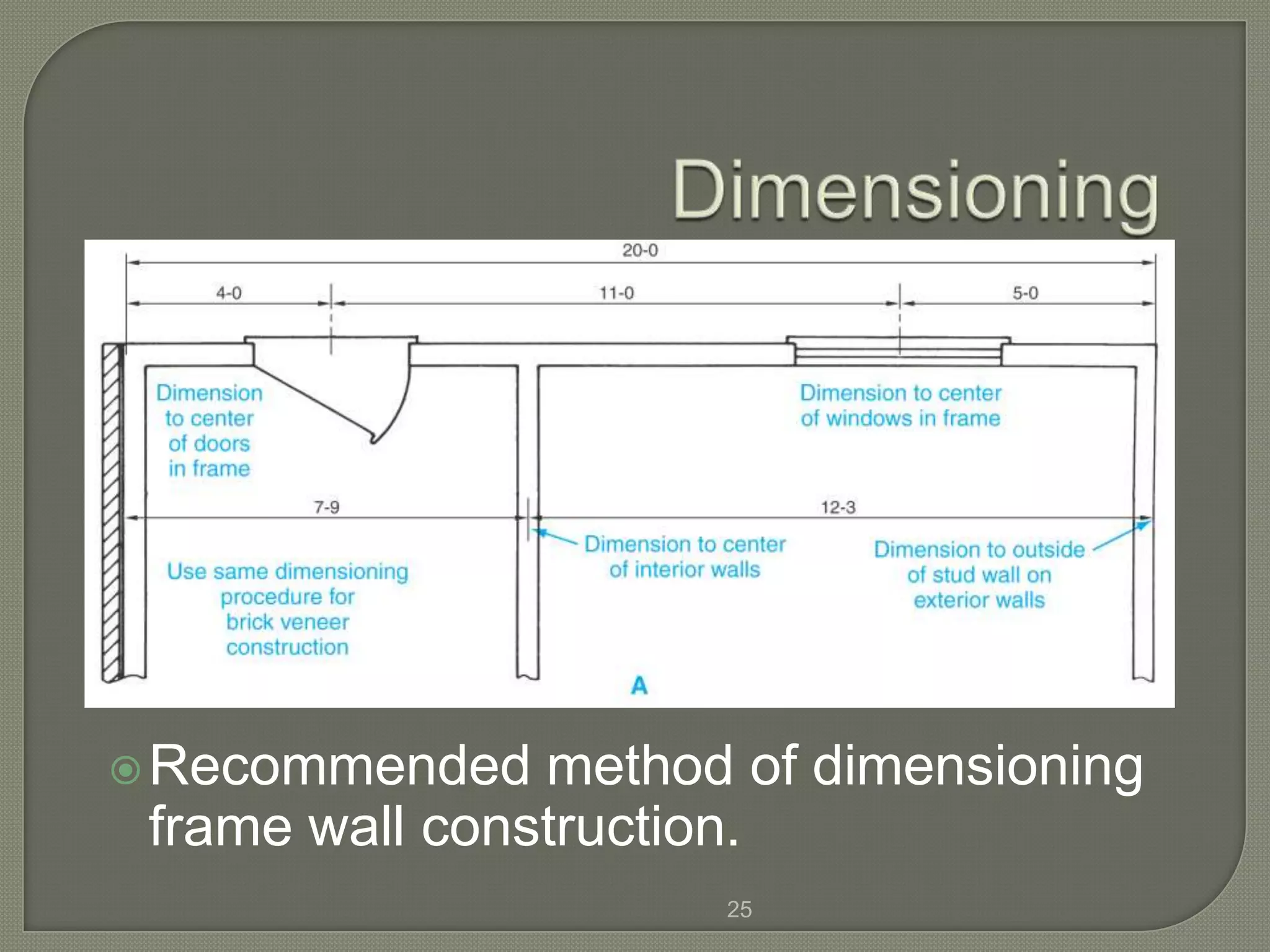
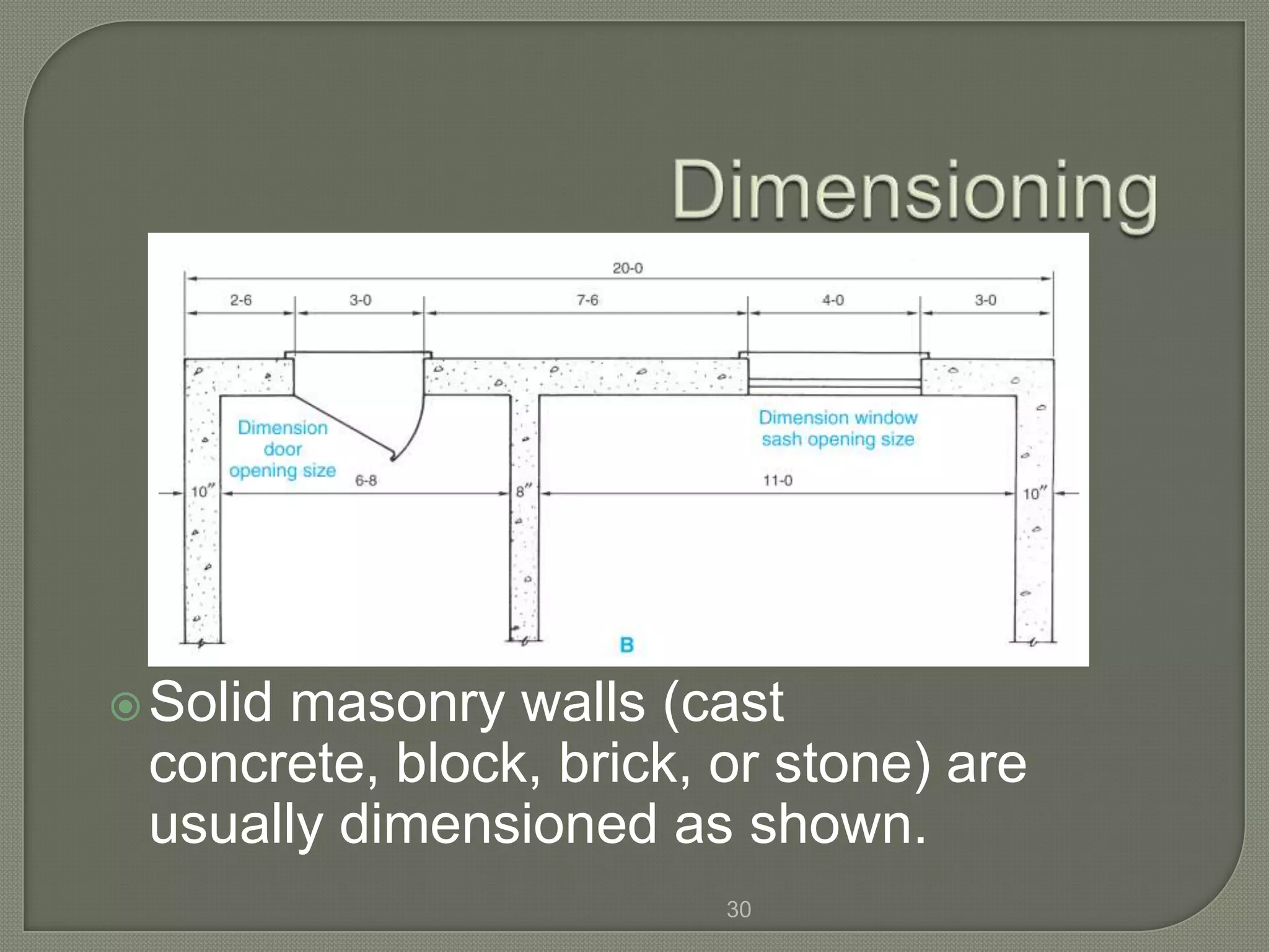
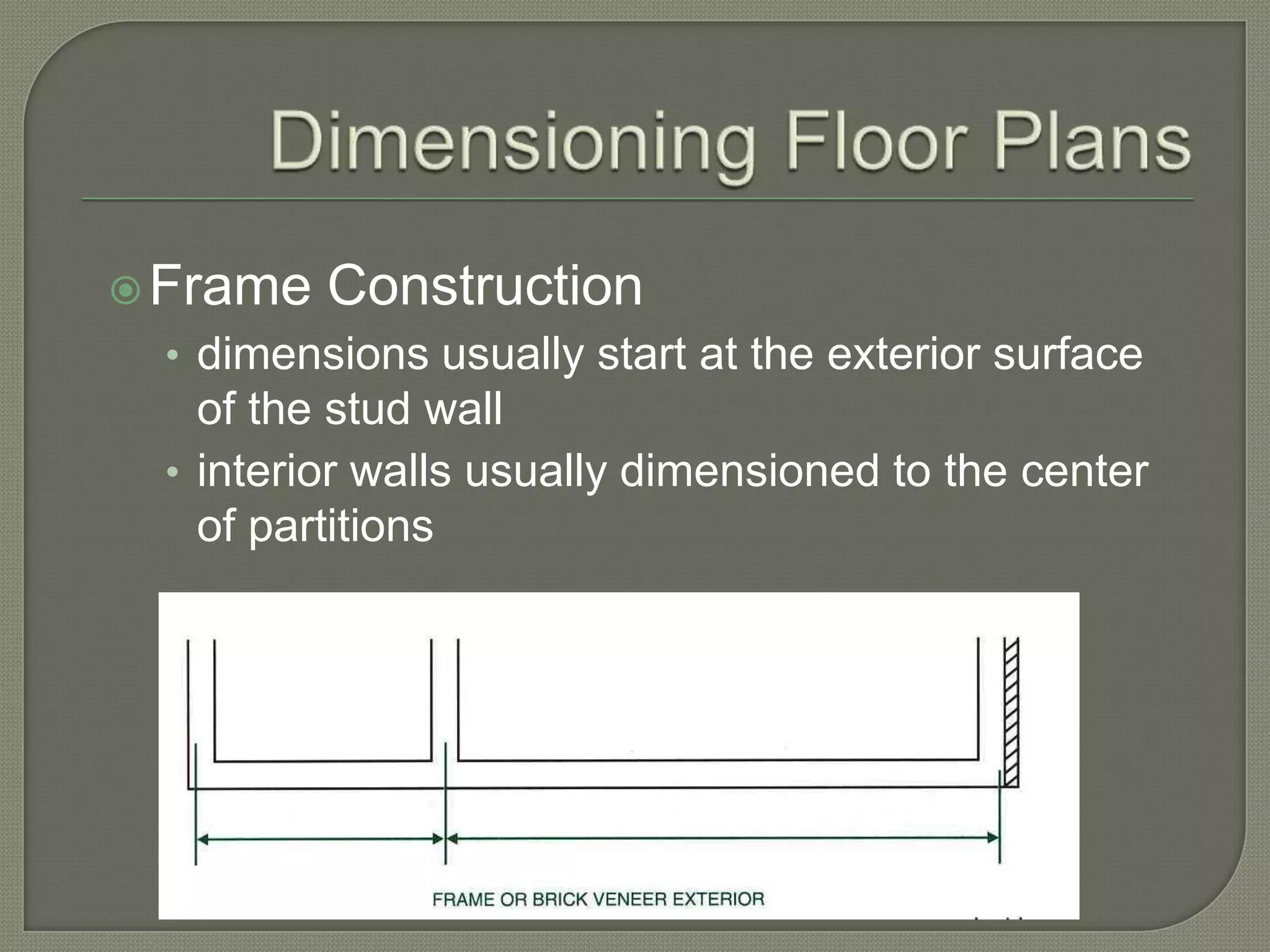
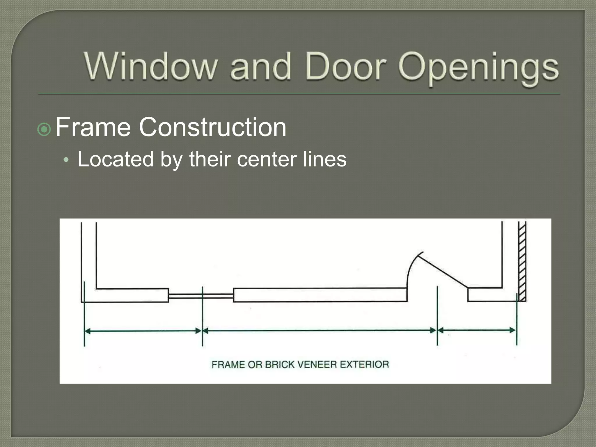
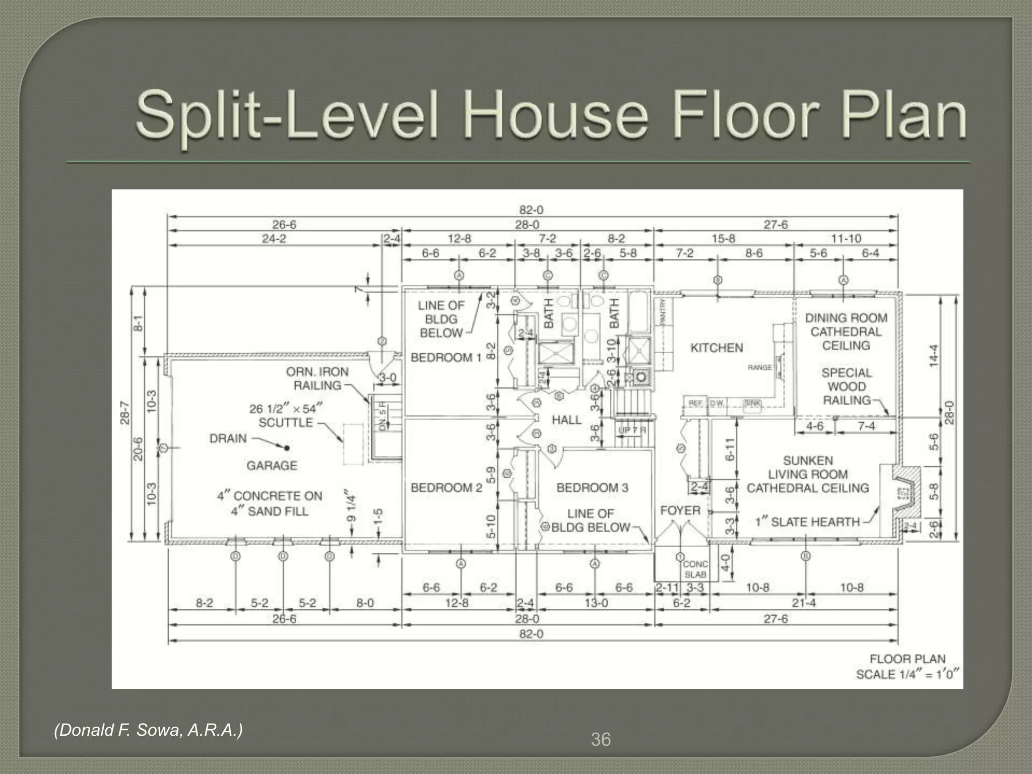
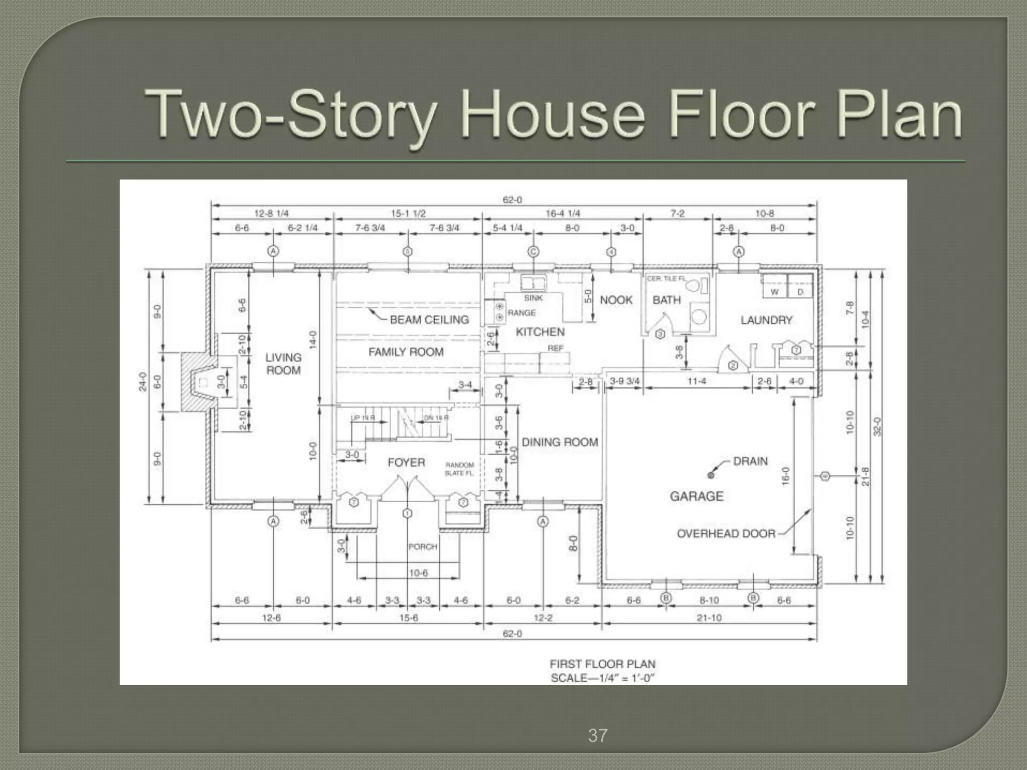
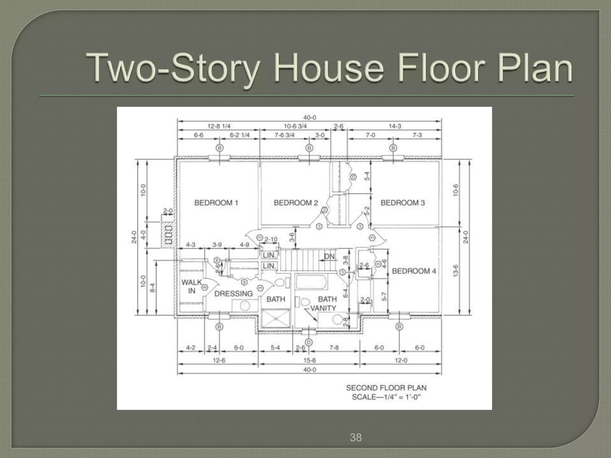
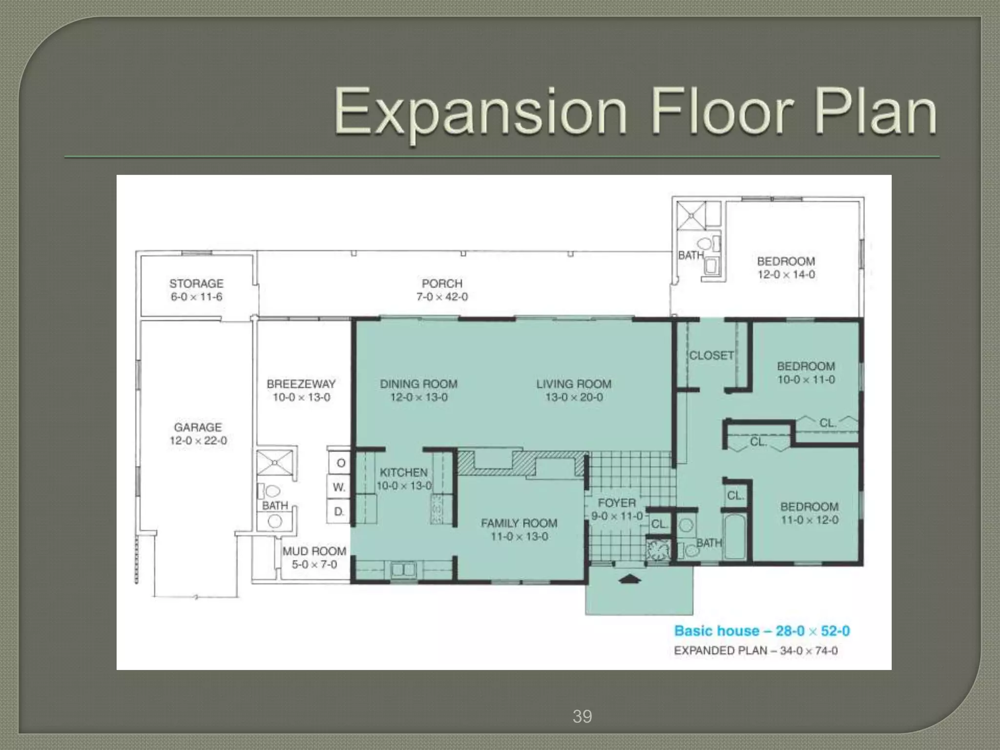
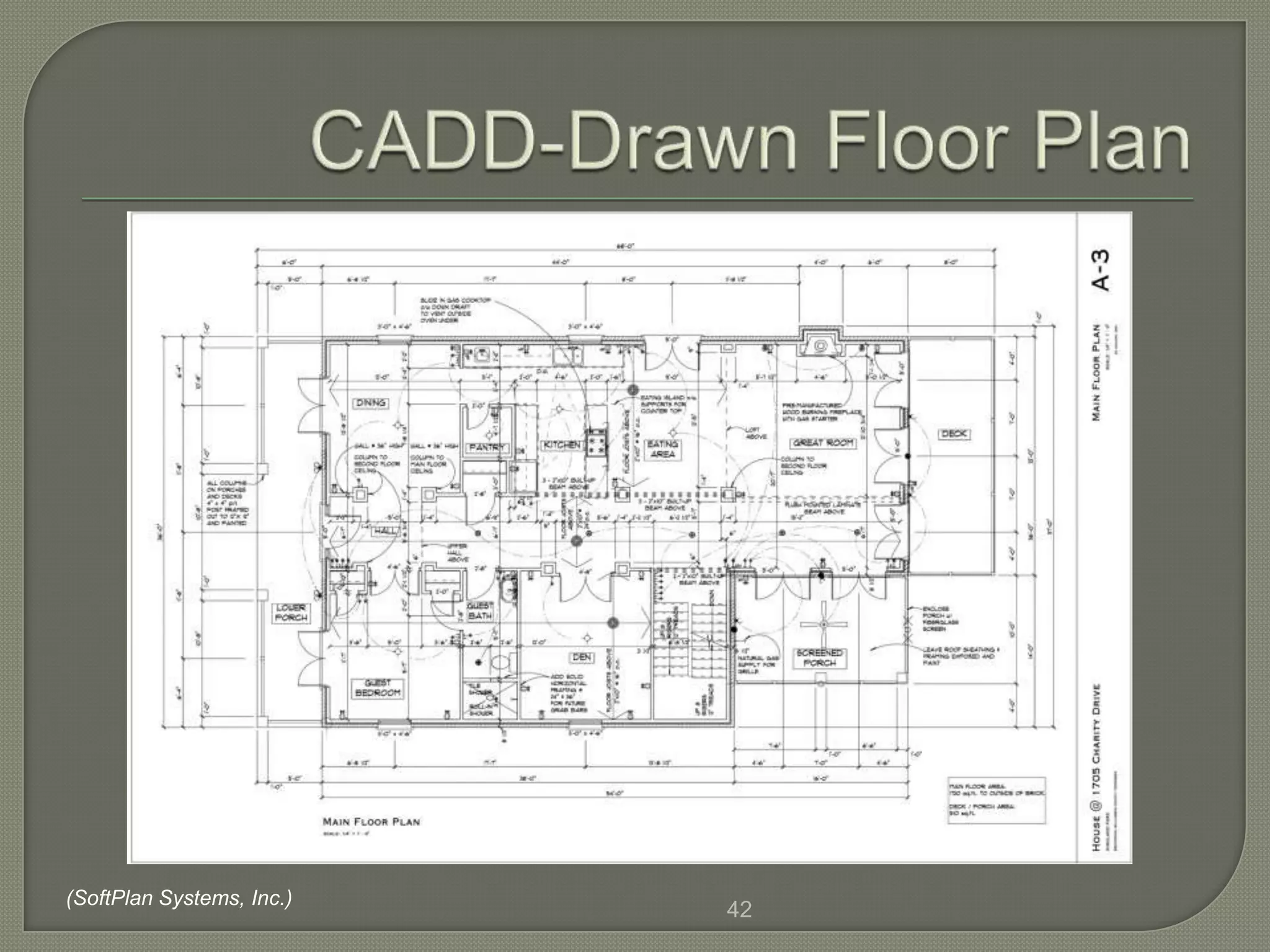
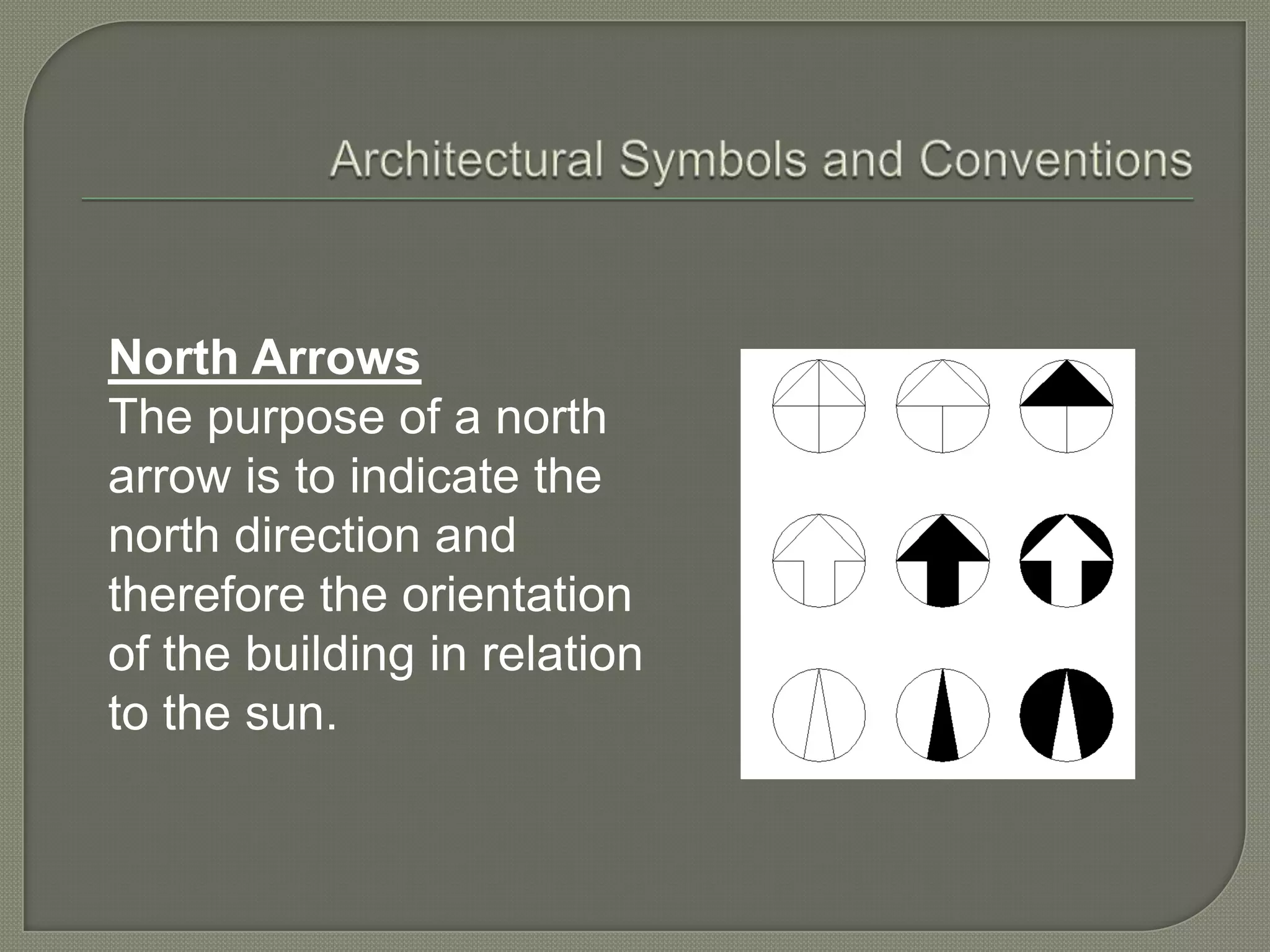
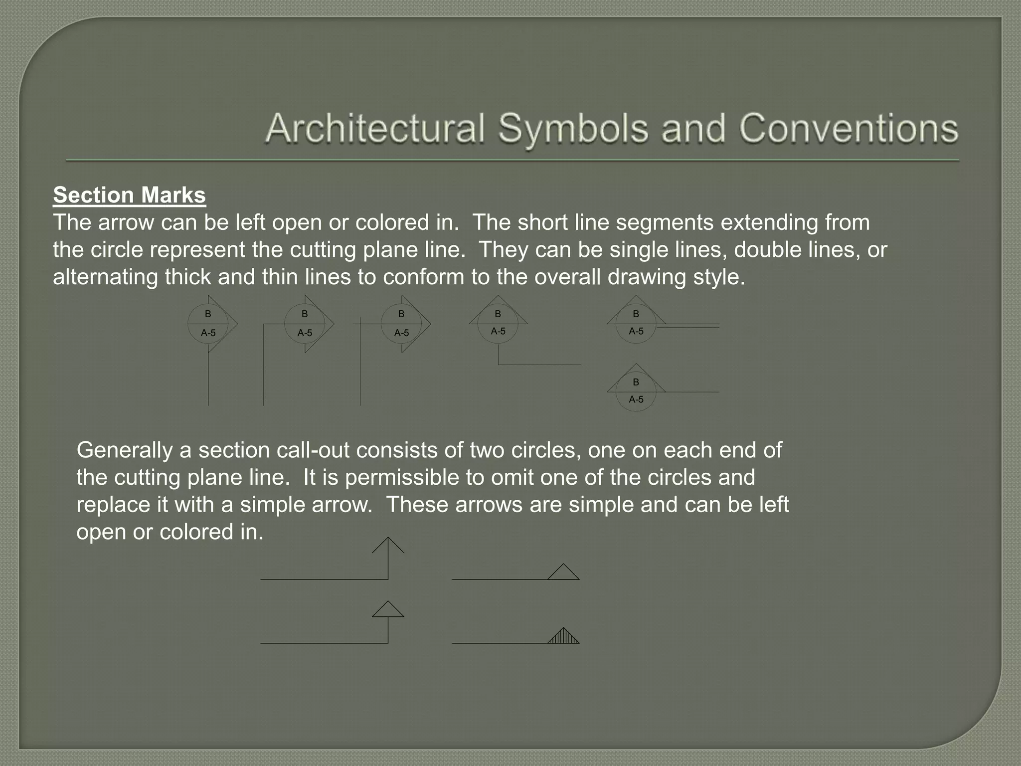
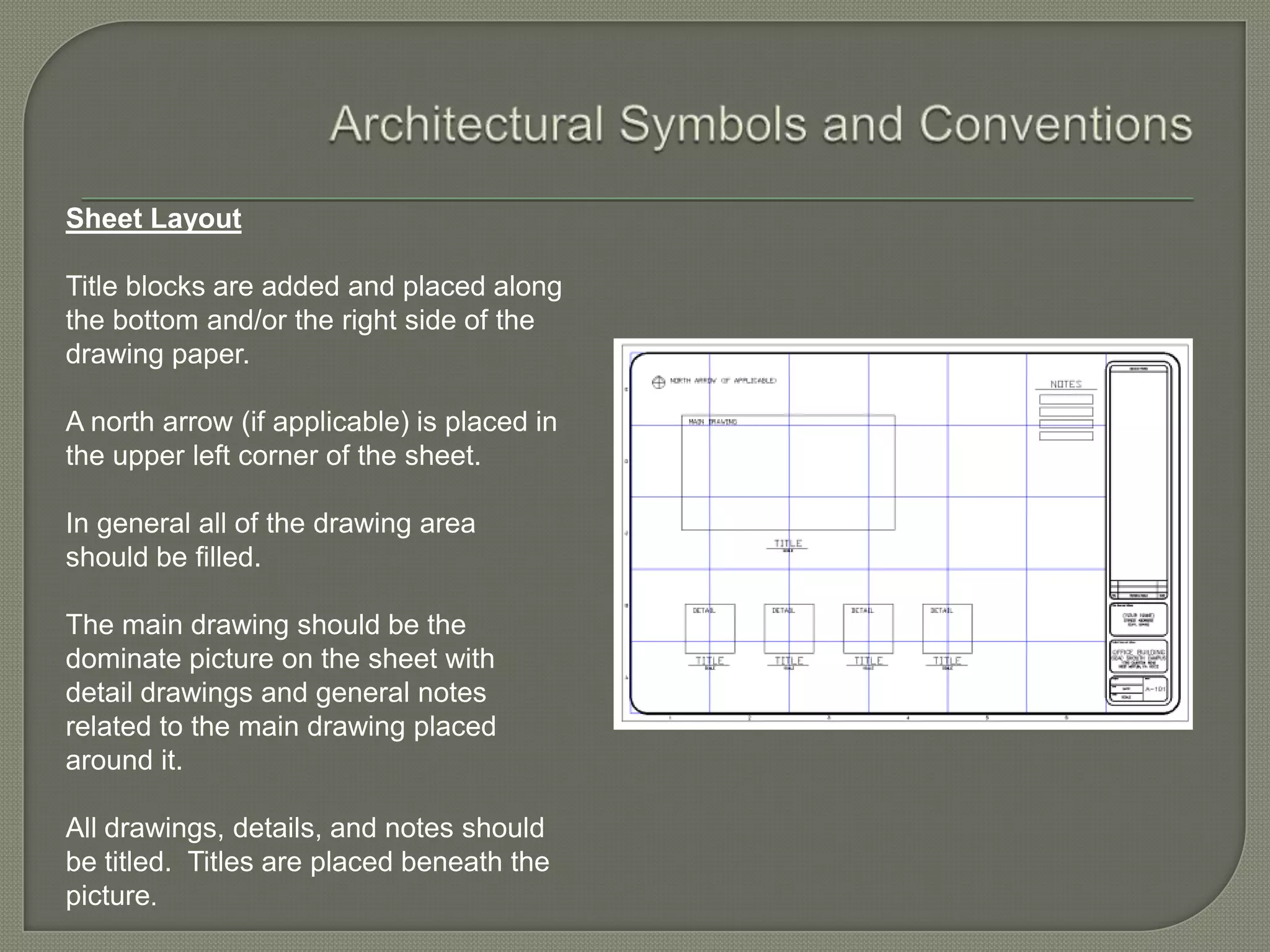
Floor Plan Dimensioning
 Thefloor plan is the heart of a set of
 construction drawings.
  • All trade workers refer to the floor plan.
  • The floor plan is the basis for many other
    plans.
  • Actually a section drawing.


                                4
 Information  that should be included on the floor
 plan includes:
  • Exterior and interior walls.
  • Size and location of windows and doors.
  • Built-in cabinets and appliances.
  • Permanent fixtures.
  • Stairs.
  • Fireplaces.

                                        (continued)
                               5
• Walks, patios, and decks.
• Room names.
• Material symbols.
• Location and size dimensions.
• Drawing scale.
• Related structures are frequently
 included.

                      6
 Many     common
     features found on
     a floor plan are
     identified in this
     drawing.


(Sater Design Collection, Inc.)
                                  7
Materialsymbols or material
 hatch patterns are used to
 denote each material.


                  8
9
10
11
Only   information about the basic
 size and location of stairs and
 fireplaces will usually be recorded
 on the floor plan.
Stairs will show direction of
 flight, number of risers, and width of
 stairs.
Fireplaces will show basic depth
 and width, opening design, and
                       12
A fireplace may be
 represented using
 a simplified or
 detailed symbol.
 The detailed
 symbol is usually
 preferred.

                      13
   Note Information about a set of stairs that is typically
    included on the floor plan. The note shown “UP 14 R”
    tells the reader that the set of stairs has 14 risers. The
    width of the stairs shown is given as 4’ from the
    center of the walls on each side of the stairs.
                                     14
 Centerlines  are used to locate the
  openings for windows and doors in
  frame walls.
 Dimensions are given to the side of the
  openings in a masonry wall.
 Openings for windows are sash width.
 Openings for doors are actual width.
 Sills are drawn for windows and exterior
  doors.
 Door swing is usually indicated.
                         15
   Windows and doors should be located in a
    frame wall using a centerline. Door swing is
    also shown. Notice that the dimension from the
    outside wall to the center of the door is 4’-6”
                               16
 Hidden (dashed) lines are used to
 show that an opening does not extend
 to the ceiling.
                      17
 Alphabet  of lines: commonly used
 architectural drawings

 Phantom    line – alternate
  positions, repeated details, and paths of
  motion
 Visible lines – outline of buildings and
  walls
 Hidden lines – edges of surface that are
  not visible
 Center lines – center of an arc or circle
 Dimension and extensions lines – extent
  and direction for measurements
  • Dimension – size and location
  • Extension – termination point of dimension
 Break lines – object continues on, but the
  complete view is not shown
 Section lines – feature that has been
  sectioned, crosshatch lines
 Symbols:   represent plumbing, electrical
 fixtures, doors, windows, and other objects
 in a house
Kitchen  cabinets, bath
 vanities, fixtures, and appliances
 are also shown on the floor plan.
We must learn to recognize
 standard symbols which are used
 for these features.

                    21
Several  outside features are usually
 included on the floor plan.
Walks, patios, and decks are
 examples.
The size and materials are typically
 noted on the plan.
Consider these elements as part of
 the total plan.
                       22
 Standards   are different in different career
  areas.
 Civil, Electrical, Construction and other
  areas follow similar practices, but
  sometimes with less need for precision in
  measurements.
 Dimensioned drawings are a part of a
  contractual document.
 Dimensions   on a floor plan show size
  and location of the features.
 In architectural drafting, dimension lines
  are continuous lines with the dimension
  figure placed above the line.


                          24
 Recommended   method of dimensioning
 frame wall construction.
                      25
 Various means   to terminating ends
  • arrow head
  • dot
  • tick

 Normally,dimensions are shown ABOVE
  dimension line

 Ifdimension is needed for construction, it
  should be on drawing
 Dimension   figures are always parallel to
  the dimension line.
 There is consistency with the type of
  termination symbol used for dimension
 lines. (arrow head, tic mark or dots)
 The following slide shows the different
  methods of ending the dimension lines


                          27
 Dimensions   are recorded in feet and
  inches.
 Feet and inch marks may be omitted.
 Dimensions less than 1' are usually
  indicated as 1/2", 2", 6", etc.
 Dimensions for interior frame walls are
  to the center of the wall.
 Dimensions for exterior frame walls are
  to the outside of the stud wall.

                         29
 Solid
      masonry walls (cast
 concrete, block, brick, or stone) are
 usually dimensioned as shown.
                         30
 Brick veneer walls are dimensioned to the
  outside of the stud wall.
 Solid masonry walls are dimensioned to
  the outside of the wall.
 Overall dimensions are needed to provide
  the total length and width of the structure
  or major parts of the structure.


                           31
 Notes  are often necessary to present
  information that cannot be represented by
  dimensions or symbols.
 Notes are usually placed so as to be read
  from the bottom of the sheet.
 There are two types of notes used:
     General Notes and Specific Notes


                         32
 Frame   Construction
 • dimensions usually start at the exterior surface
   of the stud wall
 • interior walls usually dimensioned to the center
   of partitions
 Frame   Construction
 • Located by their center lines
 Masonry   Construction
  • Openings are dimensioned to the edges of the
   masonry surface openings
(Donald F. Sowa, A.R.A.)
                           36
37
38
39
 Using  CADD speeds up the process of
  drawing and designing a floor plan.
 Automatic wall generation, repetitive use of
  symbols, dimensioning features, and
  elimination of hand lettering reduce
  drafting time.


                          40
 Residential    floor plans are usually drawn at
 1/4" = 1'-0".


                             41
(SoftPlan Systems, Inc.)
                           42
 Shows   an object like you would see in a
  photograph
 Give a three dimensional view of a room or
  structure
 Three common types
  • Isometric
  • Oblique
  • Perspective
North Arrows
The purpose of a north
arrow is to indicate the
north direction and
therefore the orientation
of the building in relation
to the sun.
Section Marks
Section marks are used to indicate where sections are being taken or cut.
Architectural practices are very similar to that used in engineering drawing.
Because of the complexity of architectural drawings cutting plane lines are
generally omitted and only the arrow indicating the direction of sight of the section
view is shown. The section call-out consists of a 1/2" diameter circle, an arrow
indication the direction of sight, and two numbers. The upper number/letter
indicates the name of the section on the sheet and the lower number refers to the
sheet where the section view is drawn.

The lettering in the section call-out circle is always horizontal regardless of the
direction of the arrow. The arrow is a 45 degree line, tangent to the circle.
                                        Name of the section view


                          B
                         A-5                                          B               B
                                                                      A-5             A-5
                                        Sheet reference
Section Marks
The arrow can be left open or colored in. The short line segments extending from
the circle represent the cutting plane line. They can be single lines, double lines, or
alternating thick and thin lines to conform to the overall drawing style.
               B         B          B         B             B
               A-5       A-5       A-5       A-5            A-5


                                                            B
                                                            A-5


  Generally a section call-out consists of two circles, one on each end of
  the cutting plane line. It is permissible to omit one of the circles and
  replace it with a simple arrow. These arrows are simple and can be left
  open or colored in.
Title Blocks
Title blocks are a very important part of the
overall drawing. They contain information
not given directly on the drawing with
dimensions or notes. The following
information is generally provided in the title
block:

   Title of the project/name of the drawing
   Name and address of the client.
   Name and address of the architectural
   company.
   Date of the completion of the drawing
   package.
   Scale of the drawing.
   Drawing Number.
   Architect's professional stamp.
Sheet Layout

Title blocks are added and placed along
the bottom and/or the right side of the
drawing paper.

A north arrow (if applicable) is placed in
the upper left corner of the sheet.

In general all of the drawing area
should be filled.

The main drawing should be the
dominate picture on the sheet with
detail drawings and general notes
related to the main drawing placed
around it.

All drawings, details, and notes should
be titled. Titles are placed beneath the
picture.
Architectural Drafting Line Work
Lines used in architectural drafting will conform to the recommended ANSI drafting
standards.

Visible Object lines are the most important lines on the drawing, therefore they are
made thick and dense black.

Border lines are made thicker than visible object lines to contrast strongly with all
other lines on the drawing.

Hidden lines are dashed lines with 1/8" dashes and 1/16" spaces. Hidden lines will
represent an item(s) not able to be seen in a particular view.

Center lines are thin, dense black lines. A center line is traditionally a long line-
dash-long line center line. This type of line is used wherever possible. Center lines
are used to indicate the center of an object or feature.

Lines used for dimensioning, crosshatching lines. match lines, and conventional
break lines are drawn as thin, dense black lines.
Architectural Drafting Line Work
Arrowheads can be either open, closed, solid, or the
traditional slash as shown.

Other types of symbols can be used in place of the
arrowhead or slash. These include
triangles, perpendicular lines, and dots.

In all cases, the style of arrowheads should not be
mixed on a drawing.              OPEN

                                 CLOSED

                                 SOLID

                                 SLASH
Dimensioning
The dimension line is a continuous, unbroken line with
the dimension figure placed above the line.

The Aligned system is used as opposed to the
unidirectional system of dimensioning.

                        16'-0"
Buildings in Plan
The plan view of a building should emphasize the horizontal dimensions of
the structure and therefore the edges should be drawn bold, sharp, and
accurately
Buildings in Plan
A building with a pitched roof should be
textured to increase the
three-dimensional quality. The
direction of the lines can emphasize
the actual building materials and the
direction in which they were laid or
emphasize the slop of pitched
surfaces. The sun side of the roof
should have a lighter texture than the
shaded side or simply left white.


The simplest way to highlight a
structure is to crosshatch the entire
building area or hatch around the
perimeter of the structure. The overall
representation of the structure should
conform to the overall style of the
drawing and the other symbols used.

Reading floor plans

  • 1.
  • 2.
     Thefloor planis the heart of a set of construction drawings. • All trade workers refer to the floor plan. • The floor plan is the basis for many other plans. • Actually a section drawing. 4
  • 3.
     Information that should be included on the floor plan includes: • Exterior and interior walls. • Size and location of windows and doors. • Built-in cabinets and appliances. • Permanent fixtures. • Stairs. • Fireplaces. (continued) 5
  • 4.
    • Walks, patios,and decks. • Room names. • Material symbols. • Location and size dimensions. • Drawing scale. • Related structures are frequently included. 6
  • 5.
     Many common features found on a floor plan are identified in this drawing. (Sater Design Collection, Inc.) 7
  • 6.
    Materialsymbols or material hatch patterns are used to denote each material. 8
  • 7.
  • 8.
  • 9.
  • 10.
    Only information about the basic size and location of stairs and fireplaces will usually be recorded on the floor plan. Stairs will show direction of flight, number of risers, and width of stairs. Fireplaces will show basic depth and width, opening design, and 12
  • 11.
    A fireplace maybe represented using a simplified or detailed symbol. The detailed symbol is usually preferred. 13
  • 12.
    Note Information about a set of stairs that is typically included on the floor plan. The note shown “UP 14 R” tells the reader that the set of stairs has 14 risers. The width of the stairs shown is given as 4’ from the center of the walls on each side of the stairs. 14
  • 13.
     Centerlines are used to locate the openings for windows and doors in frame walls.  Dimensions are given to the side of the openings in a masonry wall.  Openings for windows are sash width.  Openings for doors are actual width.  Sills are drawn for windows and exterior doors.  Door swing is usually indicated. 15
  • 14.
    Windows and doors should be located in a frame wall using a centerline. Door swing is also shown. Notice that the dimension from the outside wall to the center of the door is 4’-6” 16
  • 15.
     Hidden (dashed)lines are used to show that an opening does not extend to the ceiling. 17
  • 16.
     Alphabet of lines: commonly used architectural drawings  Phantom line – alternate positions, repeated details, and paths of motion  Visible lines – outline of buildings and walls  Hidden lines – edges of surface that are not visible
  • 17.
     Center lines– center of an arc or circle  Dimension and extensions lines – extent and direction for measurements • Dimension – size and location • Extension – termination point of dimension  Break lines – object continues on, but the complete view is not shown  Section lines – feature that has been sectioned, crosshatch lines
  • 18.
     Symbols: represent plumbing, electrical fixtures, doors, windows, and other objects in a house
  • 19.
    Kitchen cabinets,bath vanities, fixtures, and appliances are also shown on the floor plan. We must learn to recognize standard symbols which are used for these features. 21
  • 20.
    Several outsidefeatures are usually included on the floor plan. Walks, patios, and decks are examples. The size and materials are typically noted on the plan. Consider these elements as part of the total plan. 22
  • 21.
     Standards are different in different career areas.  Civil, Electrical, Construction and other areas follow similar practices, but sometimes with less need for precision in measurements.  Dimensioned drawings are a part of a contractual document.
  • 22.
     Dimensions on a floor plan show size and location of the features.  In architectural drafting, dimension lines are continuous lines with the dimension figure placed above the line. 24
  • 23.
     Recommended method of dimensioning frame wall construction. 25
  • 24.
     Various means to terminating ends • arrow head • dot • tick  Normally,dimensions are shown ABOVE dimension line  Ifdimension is needed for construction, it should be on drawing
  • 25.
     Dimension figures are always parallel to the dimension line.  There is consistency with the type of termination symbol used for dimension  lines. (arrow head, tic mark or dots)  The following slide shows the different methods of ending the dimension lines 27
  • 27.
     Dimensions are recorded in feet and inches.  Feet and inch marks may be omitted.  Dimensions less than 1' are usually indicated as 1/2", 2", 6", etc.  Dimensions for interior frame walls are to the center of the wall.  Dimensions for exterior frame walls are to the outside of the stud wall. 29
  • 28.
     Solid masonry walls (cast concrete, block, brick, or stone) are usually dimensioned as shown. 30
  • 29.
     Brick veneerwalls are dimensioned to the outside of the stud wall.  Solid masonry walls are dimensioned to the outside of the wall.  Overall dimensions are needed to provide the total length and width of the structure or major parts of the structure. 31
  • 30.
     Notes are often necessary to present information that cannot be represented by dimensions or symbols.  Notes are usually placed so as to be read from the bottom of the sheet.  There are two types of notes used:  General Notes and Specific Notes 32
  • 31.
     Frame Construction • dimensions usually start at the exterior surface of the stud wall • interior walls usually dimensioned to the center of partitions
  • 32.
     Frame Construction • Located by their center lines
  • 33.
     Masonry Construction • Openings are dimensioned to the edges of the masonry surface openings
  • 34.
    (Donald F. Sowa,A.R.A.) 36
  • 35.
  • 36.
  • 37.
  • 38.
     Using CADD speeds up the process of drawing and designing a floor plan.  Automatic wall generation, repetitive use of symbols, dimensioning features, and elimination of hand lettering reduce drafting time. 40
  • 39.
     Residential floor plans are usually drawn at 1/4" = 1'-0". 41
  • 40.
  • 41.
     Shows an object like you would see in a photograph  Give a three dimensional view of a room or structure  Three common types • Isometric • Oblique • Perspective
  • 43.
    North Arrows The purposeof a north arrow is to indicate the north direction and therefore the orientation of the building in relation to the sun.
  • 44.
    Section Marks Section marksare used to indicate where sections are being taken or cut. Architectural practices are very similar to that used in engineering drawing. Because of the complexity of architectural drawings cutting plane lines are generally omitted and only the arrow indicating the direction of sight of the section view is shown. The section call-out consists of a 1/2" diameter circle, an arrow indication the direction of sight, and two numbers. The upper number/letter indicates the name of the section on the sheet and the lower number refers to the sheet where the section view is drawn. The lettering in the section call-out circle is always horizontal regardless of the direction of the arrow. The arrow is a 45 degree line, tangent to the circle. Name of the section view B A-5 B B A-5 A-5 Sheet reference
  • 45.
    Section Marks The arrowcan be left open or colored in. The short line segments extending from the circle represent the cutting plane line. They can be single lines, double lines, or alternating thick and thin lines to conform to the overall drawing style. B B B B B A-5 A-5 A-5 A-5 A-5 B A-5 Generally a section call-out consists of two circles, one on each end of the cutting plane line. It is permissible to omit one of the circles and replace it with a simple arrow. These arrows are simple and can be left open or colored in.
  • 46.
    Title Blocks Title blocksare a very important part of the overall drawing. They contain information not given directly on the drawing with dimensions or notes. The following information is generally provided in the title block: Title of the project/name of the drawing Name and address of the client. Name and address of the architectural company. Date of the completion of the drawing package. Scale of the drawing. Drawing Number. Architect's professional stamp.
  • 47.
    Sheet Layout Title blocksare added and placed along the bottom and/or the right side of the drawing paper. A north arrow (if applicable) is placed in the upper left corner of the sheet. In general all of the drawing area should be filled. The main drawing should be the dominate picture on the sheet with detail drawings and general notes related to the main drawing placed around it. All drawings, details, and notes should be titled. Titles are placed beneath the picture.
  • 48.
    Architectural Drafting LineWork Lines used in architectural drafting will conform to the recommended ANSI drafting standards. Visible Object lines are the most important lines on the drawing, therefore they are made thick and dense black. Border lines are made thicker than visible object lines to contrast strongly with all other lines on the drawing. Hidden lines are dashed lines with 1/8" dashes and 1/16" spaces. Hidden lines will represent an item(s) not able to be seen in a particular view. Center lines are thin, dense black lines. A center line is traditionally a long line- dash-long line center line. This type of line is used wherever possible. Center lines are used to indicate the center of an object or feature. Lines used for dimensioning, crosshatching lines. match lines, and conventional break lines are drawn as thin, dense black lines.
  • 49.
    Architectural Drafting LineWork Arrowheads can be either open, closed, solid, or the traditional slash as shown. Other types of symbols can be used in place of the arrowhead or slash. These include triangles, perpendicular lines, and dots. In all cases, the style of arrowheads should not be mixed on a drawing. OPEN CLOSED SOLID SLASH
  • 50.
    Dimensioning The dimension lineis a continuous, unbroken line with the dimension figure placed above the line. The Aligned system is used as opposed to the unidirectional system of dimensioning. 16'-0"
  • 51.
    Buildings in Plan Theplan view of a building should emphasize the horizontal dimensions of the structure and therefore the edges should be drawn bold, sharp, and accurately
  • 52.
    Buildings in Plan Abuilding with a pitched roof should be textured to increase the three-dimensional quality. The direction of the lines can emphasize the actual building materials and the direction in which they were laid or emphasize the slop of pitched surfaces. The sun side of the roof should have a lighter texture than the shaded side or simply left white. The simplest way to highlight a structure is to crosshatch the entire building area or hatch around the perimeter of the structure. The overall representation of the structure should conform to the overall style of the drawing and the other symbols used.