The architectural workingdrawings and the specifications
are the most important parts of the documents constituting
the contract. Information on the designs, locations, and
dimensions of the elements of a building is found on the
architectural working drawings while information on the
quality of materials and workmanship is found in the
specifications. A good architectural working drawing gives
the contractor the exact information he needs. It should be
clear, simple, and orderly arranged, and accurately drawn so
that scaled measurements will match with dimensions.
ARCHITECTURAL WORKING DRAWINGS
3.
The finished drawingsmade by the architect, or draftsman
and used by the contractor are called architectural working
drawings. The architectural working drawings, together with
the specifications and the general conditions, form the legal
contract between the owner and the contractor. Since the
working drawings are a major portion of the contract
documents, they should be very carefully drawn.
ARCHITECTURAL WORKING DRAWINGS
4.
Elements of Architecturalworking drawing.
A complete architectural working drawing of a house generally includes the following:
1. Architectural sheets
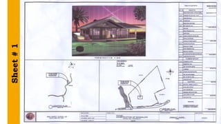
a. Sheet # 1 - Title page and index (Exterior perspective, site
development plan or plot plan, and vicinity map or location
plan is often included in the plan).
PERSPECTIVE is the view as seen by the eyes or it shows the
appearance of the finished building. This drawing represents the
actual form of the proposed building. (See perspective on the next
page).
5.
* SITE DEVELOPMENTPLAN is the outline and measurements of the
proposed building and its placement on the property. it shows the
position and the location of the building with property line, setbacks,
approaches, grade contours, landscape, and other pertinent data in
relation to the site. A site development plan is drawn using a scale not
smaller than 1:200 meters. (seesite development plan on the next page.)
* LOCATION PLAN is the top view of the site or lot where the proposed
house will be built. It shows the position of the house inside the lot, the
number of adjacent lots, streets, or lanes before or beside the lot, and the
North sign. The location plan is usually located near the title block. The
main line symbol of the North sign is generally parallel to the side border
line of the drawing paper and points upward.
Title Page andIndex generally include title block, table of contents, labels, and
the name of the duly licensed and registered Geodetic Engineer who approves the
lot survey plans.
Title Block in House Plan
The title block in house plans includes the following information:
1. Owner’s name
2. Location or address of the proposed house
3. Lot and block numbers
4. Signature of an architect or civil engineer who approves the plan
5. Draftsman’s name or initials
6. Date when the plan was drawn or completed
7. Scale as shown
8.
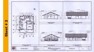
Sheet # 2
FLOORPLAN is the top view of the floor area of a house. The cutting plane line for this top
view passes between the upper and lower windowsills. It represents the arrangement of
rooms, doors, windows, and other features located in the floor plan.
ELEVATION is the front or side view of a building. It shows the design of the house, height
dimension, materials finish, and complete specification information.
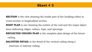
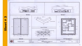
Sheet # 3
SECTIONis the view showing the inside part of the building either in
cross-section or longitudinal section.
ROOF PLAN is one showing the outline of the roof and the major object
lines indicating ridges, valleys, hips, and openings.
REFLECTED CEILING PLAN is the complete plan design of the house
ceiling.
BALUSTER DETAIL is the detail of the vertical railing along a
staircase or balcony railing.
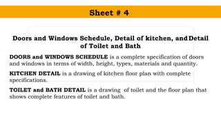
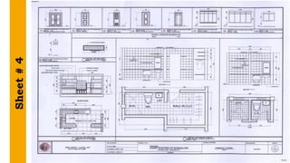
Sheet # 4
Doorsand Windows Schedule, Detail of kitchen, andDetail
of Toilet and Bath
DOORS and WINDOWS SCHEDULE is a complete specification of doors
and windows in terms of width, height, types, materials and quantity.
KITCHEN DETAIL is a drawing of kitchen floor plan with complete
specifications.
TOILET and BATH DETAIL is a drawing of toilet and the floor plan that
shows complete features of toilet and bath.
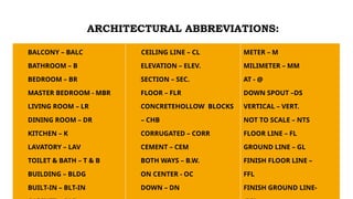
BALCONY – BALC
BATHROOM– B
BEDROOM – BR
MASTER BEDROOM - MBR
LIVING ROOM – LR
DINING ROOM – DR
KITCHEN – K
LAVATORY – LAV
TOILET & BATH – T & B
BUILDING – BLDG
BUILT-IN – BLT-IN
CEILING LINE – CL
ELEVATION – ELEV.
SECTION – SEC.
FLOOR – FLR
CONCRETEHOLLOW BLOCKS
– CHB
CORRUGATED – CORR
CEMENT – CEM
BOTH WAYS – B.W.
ON CENTER - OC
DOWN – DN
METER – M
MILIMETER – MM
AT - @
DOWN SPOUT –DS
VERTICAL – VERT.
NOT TO SCALE – NTS
FLOOR LINE – FL
GROUND LINE – GL
FINISH FLOOR LINE –
FFL
FINISH GROUND LINE-
ARCHITECTURAL ABBREVIATIONS:
15.
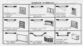
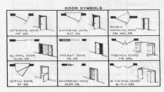
Architectural Symbols
Familiarizing allthe architectural symbols is a prerequisite
for all students in architecture and drafting technology
programs considering that their future works will be on the
architectural activity. It would be difficult for them to interpret
drawings or blueprints unless they have familiarized all the
architectural symbols.
16.
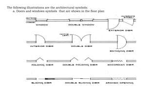
The following illustrationsare the architectural symbols:
a. Doors and windows symbols that are shown in the floor plan
20.
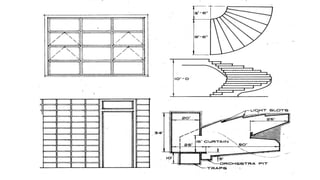
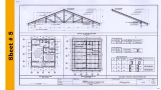
Sheet # 5
FOUNDATIONPLAN a structural excavation plan of footings and walls of
a building.
ROOF FRAMING PLAN a structural framing plan of the roof plan with
complete specification.
TRUSS DETAIL a complete structural detail of a common or typical truss
of a building.
COLUMN/FOOTING/BEAM SCHEDULE a complete specification of
column, footings, and beam in terms of sizes, materials and quantity.
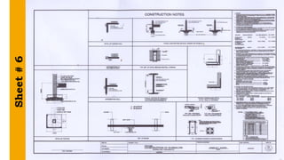
Sheet # 6
FOOTINGSis a part of the foundation directly supporting the column or
post of a house. A detailed drawing of building footings with specific
requirements.
CONSTRUCTION NOTES a sub-complete detail of wall footings, lintels,
beams, and other required structural features to present in the plan.
GENERAL NOTES a complete specification and legend of structural
features presented in the plan.
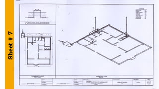
Sheet # 7
PlumbingPlan is the complete drawing detail of water and
sewage distribution.
Water System Plan is the drawing of flow of water in the house
from main water source.
Sewage System Plan is the drawing flow of sewage from the
house to the main canal and septic tank.
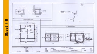
Sheet # 8
StormDrainage System shows the flow of water waste from
the lavatory, floor drain, and downspout from roof to storm
drainage.
Septic Tank it is the depository of human excreta and a
drainage reservoir for all washing done in the kitchen and
bathroom. The main section of septic tank is the digestive
chamber and the leaching well.
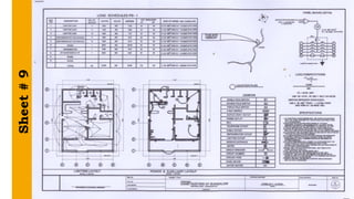
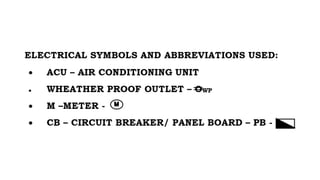
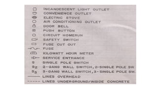
Sheet # 9
ElectricalPlan A plan consists of a lighting plan, power layout
and specification details of the house.
Lighting layout an electrical plan that shows the flow of house
lighting.
Power & auxiliary layout an electrical plan that shows the
flow of convenience outlets and other auxiliary outlets in the
floor plan.