Downloaded 157 times
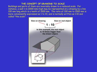

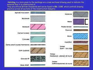
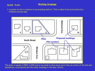
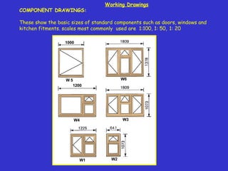
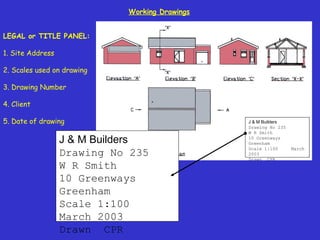
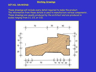
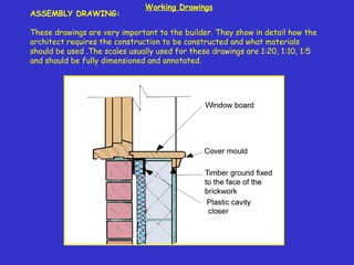

This document discusses drawing to scale and the use of scales in construction drawings. It explains that drawings represent buildings at a reduced scale, such as representing a 1m wall with a 100mm line at a 1:10 scale. Common scales for plans and elevations are listed as 1:200, 1:100, and 1:50. Hatching is used to indicate building materials. The document outlines the information that should be included in working drawings, such as dimensions, openings, and construction details in plans, elevations, sections, and other drawings. Component, assembly, and detail drawings at various scales are described.


