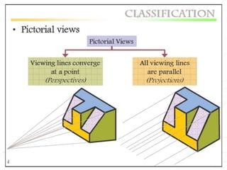
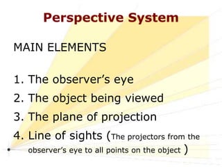
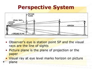
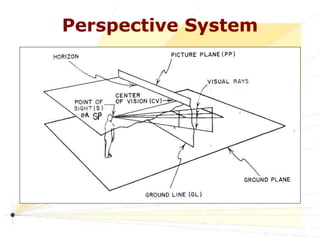
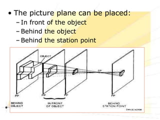
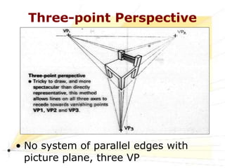
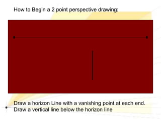
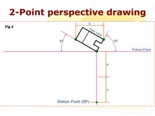
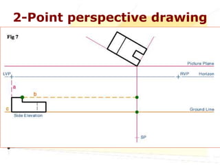
CIVIL ENGINEERING
DRAWING
Lecture : Perspective
Pictorial drawings
Perspective drawings differ from other types of
pictorial drawings. In Isometric, Dimetric, and
Trimetric drawings, remain parallel and never
converge at a single point. They are useful for
conveying technical information but lack the
quality of realism when compared to the
perspective view.
Perspective/Central projection
• Perspective is a geometric method of representing on
paper the way that objects appear in real life i.e. they
get smaller and closer together the further away they
are from the eye of an observer.
• It is the most realistic of all pictorial drawings
• It is is the way real three-dimensional objects are
pictured in a photograph that has a two-dimensional
plane
• Perspective or central projection is used in creative art
or technical sketching but seldom in technical drawing
Perspective
During the Renaissance artists
became interested in making
two-dimensional artwork look
three-dimensional.
Renaissance- (1450-1600): The
Renaissance began in Italy and
spread through Northern Europe.
Art, Science, and Literature grew
during this time.
Perspective System
MAIN ELEMENTS
1. The observer’s eye
2. The object being viewed
3. The plane of projection
4. Line of sights (The projectors from the
observer’s eye to all points on the object )
Observer’s Eye
• Observer’s eye is station point SP
• Visual ray at eye level marks horizon on picture
plane
• The central line of sight should direct towards the
centre of interest.
• For small or medium-sized objects, place SP
slightly above the object, For large objects, place
the station point at eye level
• The station point is the most influential element
of perspective drawing because it affects location,
viewpoint, and perspective.
The Object
• The position of the object changes the perspective
Plane of Projection & Projector
• The picture plane (PP) is the imaginary vertical
plane placed between the eye of the observer and
the object being drawn.
• The location of the plane of projection determines
the size of the object on the PP. Moving the PP
alters perspective or scale but not proportion.
• A picture plane, plane of projection, and drawing
surface may be the same
• Projectors are imaginary lines from the observer’s
eye to the object being drawn. The range of view
of visual rays/projectors is called the cone of vision
Vanishing Point Etc.
• The lines parallel to each other but not parallel to the
PP (horizontal lines) converge towards a single point
on the horizon - Vanishing points (VP)
• VP is also known as the centre of vision (CV).
• The horizon line (HL) is the position of horizon. HL is
also known as the eye level. The place where the land
and the sky meet.
• The ground line (GL) represents the edge of ground
plane on which object rests. GL defines the lower limit
of drawing.
Perspective
 Can you locate
the Horizon Line?
 How did you
determine this?
 Can you find the
vanishing point
in this picture?
Perspective
The red line is the Horizon Line.
Perspective
Can you locate the vanishing point?
Projectors or line of sights are not parallel to
each other
Types of Perspective
• Linear Perspective
• Aerial Perspective (Atmospheric
Perspective)
• Curvilinear Perspective (3D on 2D
• Herringborne Perspective (Lines
converge not at a VP
Perspective
Linear Perspective:
Based on the way the human eye
sees the world.
Objects that are closer appear
larger, more distant objects appear
smaller.
To create the illusion of space the
artists creates a vanishing point on
the horizon line.
Objects are drawn using orthogonal
lines, which lead to the vanishing
points.
Perspective System
• Observer’s eye is station point SP and the visual
rays are the line of sights
• Picture plane is the plane of projection or the
paper
• Visual ray at eye level marks horizon on picture
plane
Perspective System
Vanishing Point
• The lines parallel to each other but not
parallel to the picture plane converge
towards a single point on the horizon -
VANISHING POINT
Notes
• Observer’s eye is station point SP
• Visual ray at eye level marks horizon on picture plane.
The horizon line (HL) is the position of horizon.
• The central line of sight should direct towards the
centre of interest.
• The location of the picture plane (PP) determines the
size of the object on the PP. Moving the PP alters
perspective or scale but not proportion.
• The lines parallel to each other but not parallel to the
PP (horizontal lines) converge towards a single point
on the horizon - Vanishing points (VP)
• The ground line (GL) represents the edge of ground
plane on which object rests. GL defines the lower limit
of drawing.
• The picture plane can be placed:
– In front of the object
– Behind the object
– Behind the station point
Perspectives
Types of Perspective
• 1-point perspective/Parallel
perspective
• 2-point perspective/Angular
perspective
• 3-point perspective
One-point Perspective
• One face of object is parallel to
picture plane, one VP
Two-point Perspective
• Object at angle with picture plane,
but vertical edges are parallel to
picture plane, two VP
Three-point Perspective
• No system of parallel edges with
picture plane, three VP
• Rules for perspective:
– All parallel lines that are not parallel
to the picture plane vanish at a point
– If these lines are parallel to the
ground, the vanishing point will be on
the horizon
– Lines that are parallel to the picture
plane remain parallel to one another
and do not converge to a vanishing
point
Perspective of a wooden floor
Perspective of a rug
Perspective of a door
Perspective of a window
Another Way to Look at Things:
2 Point Perspective
During the Renaissance, artists became very
interested in making two-dimensional artworks look
three-dimensional. They used mathematics and close
observation to invent "linear perspective"—a technique
that allows artists to trick the eye into seeing great
distances or 3-D forms in a 2-D artwork.
Many earlier artists were interested in showing
depth, but the results were not always accurate.
Two-point perspective is useful to show an angle rather
than face-on.
Example of Difference between 1
and 2 Point Perspective: Boxes
1 point: Front of box is
not at an angle.
2 point: Front of box
is at an angle
How to Begin a 2 point perspective drawing:
Draw a horizon Line with a vanishing point at each end.
Draw a vertical line below the horizon line
Draw Orthogonals from the top and bottom of the vertical
line to both vanishing points:
(Draw Lightly so you can erase!)
Draw 2 vertical lines between the orthogonals
where the back edge of the form will be
In 2 point perspective, most of your lines will be
orthogonals or vertical… there are almost no
horizontal lines
Draw 2 more Orthogonals, from the top edge of each back
vertical line to the opposite vanishing point.
Go over the lines outlining the box, and erase all the
orthogonals which are not part of the box.
This is what you should have: a box situated below
the horizon line.
This also works very well for something which crosses the
horizon line…. Such as a building.
Draw the horizon line with 2 vanishing points and put the
vertical line intersecting the horizon line.
Draw Orthogonals from top and bottom of the vertical line
through each vanishing point
Add the back two vertical lines
Erase the horizon line behind the box you’ve made. And
erase the orthogonals where they extend past your box
to the vanishing point.
What if this were a building? How would you make a
door and windows?
All lines, other than the vertical lines, will go through
the Vanishing points!
What if you were looking at a building on a hill? The
whole thing might be higher than the horizon line (your
eye level).
Horizon line
Horizon line
After drawing the first vertical line and the orthogonals
that go to the vanishing points, draw the 2 back vertical
lines.
Finish in the same way you did before.
What if you have 2 buildings sitting side by side, but of 2
different sizes?
You do it the same way! Start with the one closest to you.
Extend the vertical line which is a shared edge of the 2
buildings to a higher level. Draw orthogonals as you did
before, then draw verticals.
Erase extra orthogonals and the horizon line where it
goes behind the buildings. Add Windows and doors.
You can add a
street with more
orthogonals.
What about a peaked roof for a house top?
Start the same way!
Then find the center of the side that will have the peak.
Make an “X” as shown below. Draw a vertical line that
extends through the middle of the “x” up beyond the top
orthogonal.
Draw the peak from the top of the center vertical line,
touching and passing the corners of the building as shown
in red.
Draw Orthogonals from the place where your roof line stops
through the vanishing point making the lower edge of the
roof, and from the peak to the vanishing point making the
top edge. (shown in Orange)
Draw another line for the back of the roof. This line is
parallel to the angle of the front of the roof.
Erase the extra Orthogonals and the horizon line behind
the building.
Complete the lines for roof tops and bottom
edges of roof.
This will not look complete until the doors,
windows, and shading is added.
1-point perspective drawing (1)
A simple one-point perspective of
a cube is to be constructed from
a plan view
Step 1 Establish an arbitrary horizon line
(HL) depending on the eye level
you wish to portray
Step 2 Locate the picture plane (PP) so
that it does not interfere with the drawing.
(The PP may be same as HL)
1-point perspective drawing(2)
Step 3 Draw the plan view above or below
the PP (easier to draw it resting on top of
PP)
1-point perspective drawing(3)
Step 4 Draw the ground line (GL) in an
arbitrary location below and parallel to the PP
1-point perspective drawing(4)
Step 5 Locate the
station point (SP) not
less than twice the width
of the object and directly
in front of or to one side
of the plan view.
(SP may also be placed 2 or 3
times the object’s greatest length
from the nearest point of the plan
view but if placed any closer,
distortion of the perspective will
result.)
1-point perspective drawing(5)
Step 6 Project the width of the plan view to
the GL.
Step 7 Draw the elevation of the object on
GL. If the plan view of the object is touching
the PP, the elevation is true in size. If the
plan view is behind or in front of PP, the
elevation is smaller or larger, respectively
Step 8 Project a vertical line from the SP to
the HL to locate the VP
1-point perspective drawing(6)
Step 9 From the corners of the front view
(D, E, G and F), draw visual rays to VP
1-point perspective drawing(7)
Step 10 The line from point A of the plan
view to SP intersects the PP at point H. Draw a
perpendicular line from H to intersect the
visual rays (points J and K).
2-Point perspective drawing
we are going to create a 2 Point
Perspective view drawing of our subject
working from plan and elevation view
STEP 1
2-Point perspective drawing
STEP 2
The first line to draw will be the Picture
Plane
2-Point perspective drawing
STEP 3
Place the lower right corner of Plan View
on the PP and rotate it clockwise. The
choice of 30° is arbitrary, but should
provide a good view
2-Point perspective drawing
STEP 4
In Fig. 4 we will locate the Station
Point. Measure the horizontal width
of our Plan View (X) and double it.
Extend a vertical line from the corner
that touches the Picture Plane
downward. At two times X we will
locate the Station Point.
2-Point perspective drawing
STEP 5
Draw lines for the Horizon and
Ground Line Fig. 5. The location of
these lines are infinitely variable.
2-Point perspective drawing
STEP 6
Draw 2 lines from the SP that are
parallel to the bottom edges of the
Plan View Fig 6. The lines should
intersect with the PP (points a & b).
Next draw vertical lines from points a
& b to the HL. The point where these
vertical lines intersect the HL is
where the left and right vanishing
points (VPL & VPR) will be located.
2-Point perspective drawing
STEP 7
The last part of preliminary layout
will be to place the Side Elevation
view from Fig. 1 onto the GL. Project
a line (orange dashed line b) from
the top of the Elevation View to the
vertical Line Of Sight (LS) Fig. 7.
2-Point perspective drawing
STEP 8
We are now ready to start projecting
lines to the vanishing points.
Referring to Fig. 8, draw lines from
both vanishing points (VPL & VPR) to
the top and bottom reference points
of our subject (points a & b).
2-Point perspective drawing
STEP 9
To locate the vertical lines on our
subject, draw lines from the SP to
corners a & b on the Plan View Fig.
9. At the point where these lines
intersect the PP, draw vertical lines
(orange dashed lines) downward to
intersect the vanishing point
projection lines.
2-Point perspective drawing
STEP 10
Using the same procedure as shown
in Fig. 9, find the smaller features on
the subject in both the Plan View and
the Elevation View (a & c) in Fig. 10.
2-Point perspective drawing
STEP 11
Project the smaller features on the
subject in both the Plan View towards
the vanishing point projection lines
Fig. 11.
2-Point perspective drawing
STEP 12
The last step is to darken the object's
construction lines, and heavy in the
visible final edge lines, to increase
readability Fig. 12.

Perspective Drawings.ppt

  • 1.
  • 2.
    Pictorial drawings Perspective drawingsdiffer from other types of pictorial drawings. In Isometric, Dimetric, and Trimetric drawings, remain parallel and never converge at a single point. They are useful for conveying technical information but lack the quality of realism when compared to the perspective view.
  • 4.
    Perspective/Central projection • Perspectiveis a geometric method of representing on paper the way that objects appear in real life i.e. they get smaller and closer together the further away they are from the eye of an observer. • It is the most realistic of all pictorial drawings • It is is the way real three-dimensional objects are pictured in a photograph that has a two-dimensional plane • Perspective or central projection is used in creative art or technical sketching but seldom in technical drawing
  • 5.
    Perspective During the Renaissanceartists became interested in making two-dimensional artwork look three-dimensional. Renaissance- (1450-1600): The Renaissance began in Italy and spread through Northern Europe. Art, Science, and Literature grew during this time.
  • 6.
    Perspective System MAIN ELEMENTS 1.The observer’s eye 2. The object being viewed 3. The plane of projection 4. Line of sights (The projectors from the observer’s eye to all points on the object )
  • 7.
    Observer’s Eye • Observer’seye is station point SP • Visual ray at eye level marks horizon on picture plane • The central line of sight should direct towards the centre of interest. • For small or medium-sized objects, place SP slightly above the object, For large objects, place the station point at eye level • The station point is the most influential element of perspective drawing because it affects location, viewpoint, and perspective.
  • 8.
    The Object • Theposition of the object changes the perspective
  • 9.
    Plane of Projection& Projector • The picture plane (PP) is the imaginary vertical plane placed between the eye of the observer and the object being drawn. • The location of the plane of projection determines the size of the object on the PP. Moving the PP alters perspective or scale but not proportion. • A picture plane, plane of projection, and drawing surface may be the same • Projectors are imaginary lines from the observer’s eye to the object being drawn. The range of view of visual rays/projectors is called the cone of vision
  • 10.
    Vanishing Point Etc. •The lines parallel to each other but not parallel to the PP (horizontal lines) converge towards a single point on the horizon - Vanishing points (VP) • VP is also known as the centre of vision (CV). • The horizon line (HL) is the position of horizon. HL is also known as the eye level. The place where the land and the sky meet. • The ground line (GL) represents the edge of ground plane on which object rests. GL defines the lower limit of drawing.
  • 12.
    Perspective  Can youlocate the Horizon Line?  How did you determine this?  Can you find the vanishing point in this picture?
  • 13.
    Perspective The red lineis the Horizon Line.
  • 14.
    Perspective Can you locatethe vanishing point?
  • 15.
    Projectors or lineof sights are not parallel to each other
  • 16.
    Types of Perspective •Linear Perspective • Aerial Perspective (Atmospheric Perspective) • Curvilinear Perspective (3D on 2D • Herringborne Perspective (Lines converge not at a VP
  • 17.
    Perspective Linear Perspective: Based onthe way the human eye sees the world. Objects that are closer appear larger, more distant objects appear smaller. To create the illusion of space the artists creates a vanishing point on the horizon line. Objects are drawn using orthogonal lines, which lead to the vanishing points.
  • 20.
    Perspective System • Observer’seye is station point SP and the visual rays are the line of sights • Picture plane is the plane of projection or the paper • Visual ray at eye level marks horizon on picture plane
  • 21.
  • 22.
    Vanishing Point • Thelines parallel to each other but not parallel to the picture plane converge towards a single point on the horizon - VANISHING POINT
  • 23.
    Notes • Observer’s eyeis station point SP • Visual ray at eye level marks horizon on picture plane. The horizon line (HL) is the position of horizon. • The central line of sight should direct towards the centre of interest. • The location of the picture plane (PP) determines the size of the object on the PP. Moving the PP alters perspective or scale but not proportion. • The lines parallel to each other but not parallel to the PP (horizontal lines) converge towards a single point on the horizon - Vanishing points (VP) • The ground line (GL) represents the edge of ground plane on which object rests. GL defines the lower limit of drawing.
  • 24.
    • The pictureplane can be placed: – In front of the object – Behind the object – Behind the station point
  • 25.
  • 26.
    Types of Perspective •1-point perspective/Parallel perspective • 2-point perspective/Angular perspective • 3-point perspective
  • 27.
  • 28.
    One-point Perspective • Oneface of object is parallel to picture plane, one VP
  • 29.
  • 30.
    Two-point Perspective • Objectat angle with picture plane, but vertical edges are parallel to picture plane, two VP
  • 31.
  • 32.
    Three-point Perspective • Nosystem of parallel edges with picture plane, three VP
  • 33.
    • Rules forperspective: – All parallel lines that are not parallel to the picture plane vanish at a point – If these lines are parallel to the ground, the vanishing point will be on the horizon – Lines that are parallel to the picture plane remain parallel to one another and do not converge to a vanishing point
  • 34.
    Perspective of awooden floor
  • 35.
  • 36.
  • 37.
  • 38.
    Another Way toLook at Things: 2 Point Perspective During the Renaissance, artists became very interested in making two-dimensional artworks look three-dimensional. They used mathematics and close observation to invent "linear perspective"—a technique that allows artists to trick the eye into seeing great distances or 3-D forms in a 2-D artwork. Many earlier artists were interested in showing depth, but the results were not always accurate. Two-point perspective is useful to show an angle rather than face-on.
  • 39.
    Example of Differencebetween 1 and 2 Point Perspective: Boxes 1 point: Front of box is not at an angle. 2 point: Front of box is at an angle
  • 40.
    How to Begina 2 point perspective drawing: Draw a horizon Line with a vanishing point at each end. Draw a vertical line below the horizon line
  • 41.
    Draw Orthogonals fromthe top and bottom of the vertical line to both vanishing points: (Draw Lightly so you can erase!)
  • 42.
    Draw 2 verticallines between the orthogonals where the back edge of the form will be In 2 point perspective, most of your lines will be orthogonals or vertical… there are almost no horizontal lines
  • 43.
    Draw 2 moreOrthogonals, from the top edge of each back vertical line to the opposite vanishing point.
  • 44.
    Go over thelines outlining the box, and erase all the orthogonals which are not part of the box.
  • 45.
    This is whatyou should have: a box situated below the horizon line.
  • 46.
    This also worksvery well for something which crosses the horizon line…. Such as a building. Draw the horizon line with 2 vanishing points and put the vertical line intersecting the horizon line.
  • 47.
    Draw Orthogonals fromtop and bottom of the vertical line through each vanishing point
  • 48.
    Add the backtwo vertical lines
  • 49.
    Erase the horizonline behind the box you’ve made. And erase the orthogonals where they extend past your box to the vanishing point.
  • 50.
    What if thiswere a building? How would you make a door and windows? All lines, other than the vertical lines, will go through the Vanishing points!
  • 51.
    What if youwere looking at a building on a hill? The whole thing might be higher than the horizon line (your eye level). Horizon line
  • 52.
    Horizon line After drawingthe first vertical line and the orthogonals that go to the vanishing points, draw the 2 back vertical lines. Finish in the same way you did before.
  • 53.
    What if youhave 2 buildings sitting side by side, but of 2 different sizes? You do it the same way! Start with the one closest to you.
  • 54.
    Extend the verticalline which is a shared edge of the 2 buildings to a higher level. Draw orthogonals as you did before, then draw verticals.
  • 55.
    Erase extra orthogonalsand the horizon line where it goes behind the buildings. Add Windows and doors. You can add a street with more orthogonals.
  • 56.
    What about apeaked roof for a house top? Start the same way! Then find the center of the side that will have the peak. Make an “X” as shown below. Draw a vertical line that extends through the middle of the “x” up beyond the top orthogonal.
  • 57.
    Draw the peakfrom the top of the center vertical line, touching and passing the corners of the building as shown in red. Draw Orthogonals from the place where your roof line stops through the vanishing point making the lower edge of the roof, and from the peak to the vanishing point making the top edge. (shown in Orange)
  • 58.
    Draw another linefor the back of the roof. This line is parallel to the angle of the front of the roof. Erase the extra Orthogonals and the horizon line behind the building.
  • 59.
    Complete the linesfor roof tops and bottom edges of roof. This will not look complete until the doors, windows, and shading is added.
  • 60.
    1-point perspective drawing(1) A simple one-point perspective of a cube is to be constructed from a plan view Step 1 Establish an arbitrary horizon line (HL) depending on the eye level you wish to portray Step 2 Locate the picture plane (PP) so that it does not interfere with the drawing. (The PP may be same as HL)
  • 61.
    1-point perspective drawing(2) Step3 Draw the plan view above or below the PP (easier to draw it resting on top of PP)
  • 62.
    1-point perspective drawing(3) Step4 Draw the ground line (GL) in an arbitrary location below and parallel to the PP
  • 63.
    1-point perspective drawing(4) Step5 Locate the station point (SP) not less than twice the width of the object and directly in front of or to one side of the plan view. (SP may also be placed 2 or 3 times the object’s greatest length from the nearest point of the plan view but if placed any closer, distortion of the perspective will result.)
  • 64.
    1-point perspective drawing(5) Step6 Project the width of the plan view to the GL. Step 7 Draw the elevation of the object on GL. If the plan view of the object is touching the PP, the elevation is true in size. If the plan view is behind or in front of PP, the elevation is smaller or larger, respectively Step 8 Project a vertical line from the SP to the HL to locate the VP
  • 65.
    1-point perspective drawing(6) Step9 From the corners of the front view (D, E, G and F), draw visual rays to VP
  • 66.
    1-point perspective drawing(7) Step10 The line from point A of the plan view to SP intersects the PP at point H. Draw a perpendicular line from H to intersect the visual rays (points J and K).
  • 67.
    2-Point perspective drawing weare going to create a 2 Point Perspective view drawing of our subject working from plan and elevation view STEP 1
  • 68.
    2-Point perspective drawing STEP2 The first line to draw will be the Picture Plane
  • 69.
    2-Point perspective drawing STEP3 Place the lower right corner of Plan View on the PP and rotate it clockwise. The choice of 30° is arbitrary, but should provide a good view
  • 70.
    2-Point perspective drawing STEP4 In Fig. 4 we will locate the Station Point. Measure the horizontal width of our Plan View (X) and double it. Extend a vertical line from the corner that touches the Picture Plane downward. At two times X we will locate the Station Point.
  • 71.
    2-Point perspective drawing STEP5 Draw lines for the Horizon and Ground Line Fig. 5. The location of these lines are infinitely variable.
  • 72.
    2-Point perspective drawing STEP6 Draw 2 lines from the SP that are parallel to the bottom edges of the Plan View Fig 6. The lines should intersect with the PP (points a & b). Next draw vertical lines from points a & b to the HL. The point where these vertical lines intersect the HL is where the left and right vanishing points (VPL & VPR) will be located.
  • 73.
    2-Point perspective drawing STEP7 The last part of preliminary layout will be to place the Side Elevation view from Fig. 1 onto the GL. Project a line (orange dashed line b) from the top of the Elevation View to the vertical Line Of Sight (LS) Fig. 7.
  • 74.
    2-Point perspective drawing STEP8 We are now ready to start projecting lines to the vanishing points. Referring to Fig. 8, draw lines from both vanishing points (VPL & VPR) to the top and bottom reference points of our subject (points a & b).
  • 75.
    2-Point perspective drawing STEP9 To locate the vertical lines on our subject, draw lines from the SP to corners a & b on the Plan View Fig. 9. At the point where these lines intersect the PP, draw vertical lines (orange dashed lines) downward to intersect the vanishing point projection lines.
  • 76.
    2-Point perspective drawing STEP10 Using the same procedure as shown in Fig. 9, find the smaller features on the subject in both the Plan View and the Elevation View (a & c) in Fig. 10.
  • 77.
    2-Point perspective drawing STEP11 Project the smaller features on the subject in both the Plan View towards the vanishing point projection lines Fig. 11.
  • 78.
    2-Point perspective drawing STEP12 The last step is to darken the object's construction lines, and heavy in the visible final edge lines, to increase readability Fig. 12.