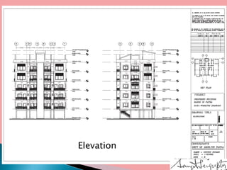
Architectural working drawings are technical drawings that provide all necessary information to construct a building project using graphical representations. They include plans, sections, elevations, schedules and specifications. The drawings are prepared according to conventions using appropriate scales, symbols and dimensions. They serve to communicate design details to construction teams, guide contractors, and obtain necessary approvals from authorities. Key components of working drawings include title blocks, site plans, floor plans, sections, elevations, structural details and specifications of finishes.
Introduction to working drawings course for architects and interior designers.
it contains 3 main parts:
1-general introduction to the course and its objectives and importance,
2-guide lines for plan drawings for beginners,
3-introduction to NCS.
This is a slide presentation of what an architect does, what are his roles in different stages of the construction industry and the types of drawings they produced.
Architectural Design Process for Beginners/StudentsGary Gilson
This presentation is intended for Semester 2/3 Architecture students who are just stepping into Architectural design from Basic Design/Other generic preparatory subjects.
This is a step-by-step visual presentation on the Architectural Design Process followed in Architecture Schools (in India). The approach to design may vary and is subject to the respective School’s philosophy and methodology.
All drawings/models/renders/sketches are used only for educational purposes and the rights and ownership of these belong to the respective Architects/Designers.
Geodesic Dome - History and ConstructionAzra Maliha
a descriptive research on history, types and construction method of a Geodesic Dome. Being sustainable, geodesic dome is being used very frequently from the past few decades. Currently, these domes are also used as residential constructions
The following presentation includes the case studies of different residential buildings. It was done by students of Pulchowk campus, Nepal in 2nd year.
it includes the form and functional aspects of residential buildings and how can we develop concepts. also it includes topics like site forces and how they have effects in design process.
Architects Professional Liability
Whether a small architecture enterprise or a multinational million dollar conglomerate, the work of architects and engineers is constantly under the spotlight. No matter how careful and exact an architect or engineer is, their work is constantly scrutinized by clients, leaving the chance of facing a lawsuit alleging negligence or failure to render professional services. Working in an industry that continues to feel the negative effects of the economy, architects and engineers cannot afford to take this risk - and that is where we can help.
GROUP HOUSING : A DOMESTIC ARCHITECTURE ACCOMODATES THE GROUP RATHER THAN THE UNIT AND ITS THEREFORE PUBLIC AS WELL AS PRIVATE. IT IS FIMILIAR THROUGH THE WIDWSPREAD DEVELOPMENT OF MASS HOUSING IN THE WORLD IN WHICH INDIVIDUALS OR FAMILIES FIND LIVING SPACE EITHER IN M ULTIPLE DWELLINGS OR SINGLE LINITS PRODUCED IN QUALITY . GROUP HOUSING IS PRODUSED BY MANY KINDS OF CULTURES BY COMMUNAL STATES TO EQALIZE LIVING STANDDARDS BY TYRANTS TO ASSURE A DOCILE LABOUR FORCE, AND BY FEDUAL OR CASTE SYSTEM TO BRINGS TOGETHER MEMBERS OF A CLASS.
2. CLUSTER HOUSING
A SUBDIVISION TECHNIQUES WHERE KNOWN
AS ZERO –LOT –LINE HOUSING OR HIGH DENSITY
HOUSING DWELLING ARE GROUPED TOGHTHER
WITH COMMON AREA LEFT FOR RECREATION .
RAW HOUSING
ONE OF A SERIES OF HOUSES , OFTEN AS SIMILAR
OR IDENTICAL DESIGN, SITUATED SIDE BY SIDE
AND JOINED COMMON WALLS
3. PRADHAN MANTRI AWAS YOJANA
2 MILLION NON-SLUM URBAN POOR HOUSEHOLD
ARE PROPOSED TO BE COVERDED UNDER THE MISSION.
RAJIV AWAS YOJANA
IT UNCOURAGE “SLUM FREE INDIA” IN CITIES
IN WHICH EVERY CITIZEN HAS ACEES TO BASIC AMENITIES.
PRADHAN MANTRI GRAMIN AWAS YOZANA
PROVIDING FINANCIAL ASSISTANCE TO RURAL
POOR FOR CONSTRUCTING THEIR HOUSES THEMSELVES.
HOUSING FOR ALL BY 2022
MISSSION APPROVED A SUBSTANCIAL INCREAS IN INTEREST
RELIFE ON LOAN FOR THE URBAN POOR
TO PROMOTE AFFORDEBLE HOMES.
INTEREST SUBSIDY SCHEMES FOR HOUSING URBAN
THE SCHEMES ENVISAGES THE PROVISION OF
INTEREST TO EWS AND LIG SEGMENTS TO
ENABLES THEM TO BUY OR CONSTRUCT HOUSES.
4.Lower Income Group
Economic Weaker Section (EWS) means households with monthly household income upto Rs. 5000/- per month or as revised by the Ministry of Housing and Urban Poverty Alleviation, Government of India from time to time. Lower Income Group (LIG) means households with monthly household income between Rs. 5001/- to Rs.
5.Development of Group Housing will be under provision
of master plan, Enclave development plan and layout plan.
Minimum area of plot will be 2000sq.m
Land proposed for group housing will be located at 12m
wide exiting road, But the distance of the plot from 18m
(or above) wide road will not be more than 100m.
Slilt floor will be permitted for the purpose of parking in
group housing buildings, height of which of which be
2.1m up to the beam.
if slilt floor is used for purpose other than parking then
it will be counted in F.A.R.
Park and open area will be provided at the rate of
1.0sq.m. per person or 15% of the whole area,
whichever is more, in the plot of area 3000sq.m (or above).
Construction Documents Guide: Types and Significance in 2024Chandresh Chudasama
Explore the various types of construction documents and their significance in 2024 in this insightful article.
This blog post will provide a detailed checklist of all the essential construction documents required for projects in 2024. It will cover everything from architectural drawings and specifications to permits and contracts. By following this guide, contractors and project managers can ensure that they have all the necessary documentation in place, saving time and avoiding potential legal issues.
1. What two major components make up the contract documents 2. .docxjeremylockett77
1. What two major components make up the contract documents?
2. When did architects first begin to use drawings to communicate their
design intent?
3. What does CAD stand for?
4. There is a particular way in which the drawings are organized in a set of drawings. Identify the order of drawings in a typical set of plans.
5. What is the difference between a plan view and a section view in a set of drawings?
6. Name the four primary sections of a project manual.
7. The 2004 CSI MasterFormat is broken down into how many divisions?
8. Under which CSI division would you find building insulation?
9. Name the four basic types of construction contracts.
10. Under a guaranteed maximum price contract, what happens if the actual cost is less than the guaranteed maximum contract price?
Construction Management Jump Start
Chapter 4
The Construction Contract
*
*
Chapter 4
The Construction ContractThis chapter introduces you to the various documents included in the contract, how the contract impacts the construction, the standard protocols used when preparing the contract documents, and the various types of contracts used for construction.
*
*
What is a Construction Contract?An agreement between the owner and contractor and is enforceable by law.Contractor is to perform a service for some consideration or payment.The contract is comprised of many documents.The plans and specs are often referred to as the contract documents and the contractor must deliver the project in accordance with them.
*
Contract DocumentsIn a traditional project delivery method, the contractor is typically not involved in the design or production of the contract documents.
Contract documents consist of two major components:Drawings (Plans) discuss the quantity of the workProject Manual (Specs) discuss the quality of the work
*
The DrawingsThe drawings are a graphical set of directives prepared by the expressing the wishes and desires of the owner.The most important communication tool used to convey the work.A shift in the design and construction process occurred during the Renaissance.Prior to the Renaissance master builders communicated design with modelsDuring the Renaissance, master builders began expressing their design through drawings and written instructions.Today models have been reintroduced to supplement drawings using 3D and 4D (4D includes time/schedule) computer modeling.
*
Drawing ProductionHistorically, drawings have been called blueprints.Blueprints were created through a process which reproduced hand-drafted drawings by printing white lines on blue paper.Todays hand-drafting process prints blue lines on white paper; these drawings are actually referred to as bluelines.However, most drawing today are produced electronically on computer aided design (CAD).
*
Drawing SizeSets of drawings vary in size from a 3-4 sheets for a small house to well over 100 sheets for large, magnificent structures.Note: A single drawing sheet is typic ...
Architectural drawing is simply the technical drawing of a house, a building, or any kind of structure. ... It's a schematic representation of a building. Architects, for instance, use architectural drawings to convey and develop a design idea into a coherent proposal. Also, they use it to communicate ideas and concepts.
The Roman Empire A Historical Colossus.pdfkaushalkr1407
The Roman Empire, a vast and enduring power, stands as one of history's most remarkable civilizations, leaving an indelible imprint on the world. It emerged from the Roman Republic, transitioning into an imperial powerhouse under the leadership of Augustus Caesar in 27 BCE. This transformation marked the beginning of an era defined by unprecedented territorial expansion, architectural marvels, and profound cultural influence.
The empire's roots lie in the city of Rome, founded, according to legend, by Romulus in 753 BCE. Over centuries, Rome evolved from a small settlement to a formidable republic, characterized by a complex political system with elected officials and checks on power. However, internal strife, class conflicts, and military ambitions paved the way for the end of the Republic. Julius Caesar’s dictatorship and subsequent assassination in 44 BCE created a power vacuum, leading to a civil war. Octavian, later Augustus, emerged victorious, heralding the Roman Empire’s birth.
Under Augustus, the empire experienced the Pax Romana, a 200-year period of relative peace and stability. Augustus reformed the military, established efficient administrative systems, and initiated grand construction projects. The empire's borders expanded, encompassing territories from Britain to Egypt and from Spain to the Euphrates. Roman legions, renowned for their discipline and engineering prowess, secured and maintained these vast territories, building roads, fortifications, and cities that facilitated control and integration.
The Roman Empire’s society was hierarchical, with a rigid class system. At the top were the patricians, wealthy elites who held significant political power. Below them were the plebeians, free citizens with limited political influence, and the vast numbers of slaves who formed the backbone of the economy. The family unit was central, governed by the paterfamilias, the male head who held absolute authority.
Culturally, the Romans were eclectic, absorbing and adapting elements from the civilizations they encountered, particularly the Greeks. Roman art, literature, and philosophy reflected this synthesis, creating a rich cultural tapestry. Latin, the Roman language, became the lingua franca of the Western world, influencing numerous modern languages.
Roman architecture and engineering achievements were monumental. They perfected the arch, vault, and dome, constructing enduring structures like the Colosseum, Pantheon, and aqueducts. These engineering marvels not only showcased Roman ingenuity but also served practical purposes, from public entertainment to water supply.
This is a presentation by Dada Robert in a Your Skill Boost masterclass organised by the Excellence Foundation for South Sudan (EFSS) on Saturday, the 25th and Sunday, the 26th of May 2024.
He discussed the concept of quality improvement, emphasizing its applicability to various aspects of life, including personal, project, and program improvements. He defined quality as doing the right thing at the right time in the right way to achieve the best possible results and discussed the concept of the "gap" between what we know and what we do, and how this gap represents the areas we need to improve. He explained the scientific approach to quality improvement, which involves systematic performance analysis, testing and learning, and implementing change ideas. He also highlighted the importance of client focus and a team approach to quality improvement.
We all have good and bad thoughts from time to time and situation to situation. We are bombarded daily with spiraling thoughts(both negative and positive) creating all-consuming feel , making us difficult to manage with associated suffering. Good thoughts are like our Mob Signal (Positive thought) amidst noise(negative thought) in the atmosphere. Negative thoughts like noise outweigh positive thoughts. These thoughts often create unwanted confusion, trouble, stress and frustration in our mind as well as chaos in our physical world. Negative thoughts are also known as “distorted thinking”.
Palestine last event orientationfvgnh .pptxRaedMohamed3
An EFL lesson about the current events in Palestine. It is intended to be for intermediate students who wish to increase their listening skills through a short lesson in power point.
How to Split Bills in the Odoo 17 POS ModuleCeline George
Bills have a main role in point of sale procedure. It will help to track sales, handling payments and giving receipts to customers. Bill splitting also has an important role in POS. For example, If some friends come together for dinner and if they want to divide the bill then it is possible by POS bill splitting. This slide will show how to split bills in odoo 17 POS.
The Indian economy is classified into different sectors to simplify the analysis and understanding of economic activities. For Class 10, it's essential to grasp the sectors of the Indian economy, understand their characteristics, and recognize their importance. This guide will provide detailed notes on the Sectors of the Indian Economy Class 10, using specific long-tail keywords to enhance comprehension.
For more information, visit-www.vavaclasses.com
Students, digital devices and success - Andreas Schleicher - 27 May 2024..pptxEduSkills OECD
Andreas Schleicher presents at the OECD webinar ‘Digital devices in schools: detrimental distraction or secret to success?’ on 27 May 2024. The presentation was based on findings from PISA 2022 results and the webinar helped launch the PISA in Focus ‘Managing screen time: How to protect and equip students against distraction’ https://www.oecd-ilibrary.org/education/managing-screen-time_7c225af4-en and the OECD Education Policy Perspective ‘Students, digital devices and success’ can be found here - https://oe.cd/il/5yV
Welcome to TechSoup New Member Orientation and Q&A (May 2024).pdfTechSoup
In this webinar you will learn how your organization can access TechSoup's wide variety of product discount and donation programs. From hardware to software, we'll give you a tour of the tools available to help your nonprofit with productivity, collaboration, financial management, donor tracking, security, and more.
Model Attribute Check Company Auto PropertyCeline George
In Odoo, the multi-company feature allows you to manage multiple companies within a single Odoo database instance. Each company can have its own configurations while still sharing common resources such as products, customers, and suppliers.
2. What is Architectural Working Drawing.
Is a organized technical drawing of a building (or
building project) having all required information and
instruction in graphical form to enable us to erect the
building/ building project on site/ground. It is called
construction documents(CD). Traditionally, working
drawings consist of 2 dimensional orthogonal projections
of the building or component they are describing, such as
plans, sections, elevations, details, schedules and
specification etc. It is a tool of communication. It is legal
foundation for the project.
3. Purpose of Architectural Working Drawing.
1. To develop a design idea into a coherent proposal.
2. To communicate technical information among design and construction
teams.
3. To provide information for preparation of structural design and
drawings for foundation, columns, beams, floor slabs , staircase and
any other structural component of a building.
4. To provide information for preparation of Acoustic Design, Electrical,
HVAC, mechanical, Fire Fighting, Plumbing, Sanitary, external &
internal finish and interior furnishing etc. drawings.
5. To provide information for preparation of specifications and detailed
estimates for civil, acoustic design, electrical, plumbing, horticulture,
landscape, site development etc. works.
6. To provide information for preparation of Bill of Quantities of various
items and materials to be used in construction of the building.
7. To guide the contractor & construction team.
8. To obtain approval of Local Self Government, Fire Department, Urban
Art Commission and other Statutory Authorities.
4. Purpose of Architectural Working Drawing.
(Cont----)
9. To provide information for preparation of tender document.
10. To show how the design is to be materialized.
11. To serve as reference for supervision of construction works at site.
12. To start and complete the execution of the construction of building
on the basis of the information given in the drawing.
13. To convey the design intent to the contractor for bidding and
construction
14. To prepare the shop drawing, to fabricate components of the works
or to assemble or install components
15. To make a record of existing building/structure and completed
works.
16. Act as a basis for ordering materials and components .
17. Assist in the measurement of construction progress
18. Records of completed works and building that
already exists.
5. How Architectural Working Drawing is prepared
Is made according to a set of conventions, which include particular views (floor
plan, section , elevations, specifications and details etc.), sheet sizes, units of
measurement and scales, annotation and cross referencing, for maintaining the
uniformity of drawing in terms of scale , line weight/thickness, line type , size of
sheet and symbols etc.
Working Drawing may be very simple or very complex depending upon the
project. The complexity of the drawing is a factor in determining the size of sheet.
Is made to show how the design is to be implemented , therefore should give the
contractor exactly the information he needs and relevant data.
Traditionally, consist of 2 dimensional orthogonal projections of the building or
component they are describing, such as plans, sections , elevations and details etc.
Includes title block, dimensions, notation, notes & symbols consistent with
industry standards so that their precise meaning is clear & can be understood.
Specification information can be included on working drawings or in a separate
specification sheet, but information should not be duplicated as this can become
contradictory and may cause confusion.
6. Criteria of good Architectural Working Drawing.
1. Accurately Drawn with appropriate symbols, notations, conventions,
graphical representation and all relevant information.
2. Information should not be duplicated as this can become contradictory
and may cause confusion.
3. Structured and dimensioned well carefully so that they convey
necessary information to carry out particular parts of the works.
4. The Layout of the drawing and text on the drawing shall be such as to
facilitate the reading of drawing and make it possible for essential
references to be located easily.
5. Drawn in appropriate scale logically and neatly arranged and properly
titled.
6. Standard abbreviations, Schedule formats, Material designations.
7. Required information for preparation of tender document.
8. Serve as reference for supervision of construction works at site.
9. The scale at which drawings are prepared should reflect the level of
detail of the information they are required to convey. Different line
thicknesses should be used to provide greater clarity for certain
elements.
7. Layout of Drawings.
1. The layout of drawings shall be such as to facilitate
the reading of drawings and make it possible for
essential references to be located easily.
2. The Standard arrangements shall include all
relevant information and sufficient margins shall
be left from the edges of finished drawings to
facilitate filing and binding where necessary.
3. Margins, the provision of blank border will enable
prints to be trimmed, if necessary, without incurring
the use of uneconomical sizes of sensitized material
to allow for trimming.
4. There should be marked with zones.
8. Basic contents of
Architectural Working
Drawings
1. Title Block
2. Site Layout Plan
3. Column Layout Plan in case of frame
structure building.
4. Foundation layout Plan in case of load
bearing structure.
5. Foundation details
6. Excavation Plans
7. Floor Plans including basement floor if
any
8. Roof Plan
9. Elevations
10. Sections
11. Services Layout plan
12. Door window Details
13. Electrical Layout & HVAC Plan
14. Plumbing layout plan
15. Structural details plan of Footings,
Columns, Beams, Slabs, Staircase etc.
16. Toilet Details
nosing, risers & tread
18. Kitchen details.
19. Iron mongaries
20. Reflected Ceiling plan
21. Typical Details of various components
& elements, like cupboard, flooring
pattern etc.
22. Specification of various finishes and
building materials
23. Shop drawings wherever required.
24. Beam- column layout
25. Brickwork layout
26. PHE drawing
27. Fire Fighting drawing.
28. Drainage system
29. Landscape, Horticulture, Circulation &
Site Development.
30. Furniture Layout
31. Acoustic Design
32. Area Calculation
33. Internal & External Colour Scheme
34. Schedules.
9. Size of Drawing Sheet.
Sl. No. Designation Trimmed Size
In mm
Untrimmed
Size in mm
1. A0 841 x 1189 880 x 1230
2. A1 594 x 841 625 x 880
3. A2 420 x 594 450 x 625
4. A3 297 x 420 330 x 450
5. A4 210 x 297 240 x 330
6. A5 148 x 210 165 x 240
The trimmed sizes are on the following basic principles
1. Two successive sizes of the series are obtained by halving or doubling. Consequently,
the surface areas of two successive sizes are in the ratio of 1:2 appx.
2. The formats or forms are geometrically similar to one another , the sides of each size
being in the ratio of 1:√2.
3. The surface area of the basic size A0 is one square metre
10. Title Block
1.The title block is an important
feature in a drawing , since it
facilitates obtaining uniformity and
presents in definite manner the
details like title of drawing, Job
Title, Name of Organization or
Firm, Name of Architect, Name of
Structural Engineer, Drawing
Number, Scale, Date of Drawing,
North Direction , Dated initials of
Technical Staff preparing checking
the drawing, Revision Panels, Key
Plan, Notes, List of Reference
Drawings, Schedules etc.
2. The width of title block shall be
150 mm.
11. Title Block ( contd.---)
Standard Notes in Title Block:
1. This Drawing has been prepared on the basis of preliminary architectural drawings
bearing number_____________.
2. All dimensions are in “mm” unless otherwise specified.
3. Drawing not to be measured only written dimensions to be followed.
4. This drawing should be read in conjunction with relevant Architectural/structural
drawing .
5. The sizes of Columns and Beams in this drawing are in accordance with Structural
Drawing number __________.
6. Any discrepancies between this drawing and correspondence/ related structural
drawing should immediately be brought to the notice of the Architect before execution
and work should not be carried out at site till the discrepancies are not removed.
7. All external walls are _____mm thick and all internal walls are _____mm thick Brick/
RCC walls unless otherwise specified.
8. The building shall be constructed in full compliance with all applicable codes,
ordinances and regulations as well as the drawings and specifications. Any code
deficiencies in the drawings recognized by the contractor should be brought to the
attention of the architect for clarification.
9. Any other notes as deemed fit by the Architect and relevant to the drawing.
12. Title Block ( contd.---)
CONSTRUCTION DOCUMENT SHEET NUMBERS AND SHEET ORDER
United States National CAD Standard:
Components of the Sheet Number:-
• There are three components that make up sheet numbers in a set of construction
documents. The first two letters, the discipline designators, identify the construction
discipline that the sheet covers - architectural sheets, plumbing sheets, structural sheets,
etc. The third digit, the sheet type, is a number that represents the type of drawings that
are on the sheet - plans, sections, details, schedules, etc. The final two digits, the
sequence numbers, are numbers that simply place the sheets in order.
• The Discipline Designator can be a single letter or a double-letter. Very large or complex
projects will want to make use of the double-letter designations to help sub-divide each
discipline further.
• The Sheet Types Designator takes the drawings of a single discipline and organizes
them. Drawings are always organized from most general to most specific or specialized.
Since plans are most helpful to see the overall design of the project, they come first.
Elevations and sections are a bit more specific and come next followed by details and
schedules, which are the most specific type of drawings.
• Sequence Number, which is two-digit between 01 and 99. The sequence numbers do not
have to be sequential so that space may be left within the set for future additions.
13. Title Block ( contd.---)
CONSTRUCTION DOCUMENT SHEET NUMBERS AND SHEET ORDER
The following table indicates the primary (single) letter designations that may be used and the order that the
disciplines should take. In this case, a hyphen shall be inserted in place of the secondary discipline designator so that
the format remains.
Designator Name Additional Description
Cover Sheet
G General Sheet list, symbols, code summary, etc.
H Hazardous Materials Abatement, handling, etc.
V Survey / Mapping
B Geotechnical
C Civil
L Landscape
S Structural
A Architectural
I Interiors
Q Equipment
F Fire Protection
P Plumbing
D Process
14. Title Block ( contd.---)
CONSTRUCTION DOCUMENT SHEET NUMBERS AND SHEET ORDER
Designator Name Additional Description
M Mechanical
E Electrical
T Telecommunications
R Resource Existing Condition/ Building
X Other Disciplines
Z Contractor / Shop Drawings
O Operations
The Sheet Types designator takes the drawings of a single discipline and organizes
them. Drawings are always organized from most general to most specific or specialized.
Since plans are most helpful to see the overall design of the project, they come first.
Elevations and sections are a bit more specific and come next followed by details and
schedules, which are the most specific type of drawings.
15. Site Layout plans
Site plans usually show the extent of the site but no surrounding detail.
Recommended scales are:
1 : 500, 1 : 200
The function of the site plan is to show:
1. The location of the proposed building or buildings with reference to a bench
mark and in relation to surroundings of the plot.
2. The topography of the site, with both existing and finished levels.
3. Existing Buildings to be demolished or removed or retained.
4. The extent of earthworks, included, cutting and filling, and the provision of
bank and retaining walls.
5. Roads, footpaths, hard standings and paved areas.
6. Planting.
7. The layout of external service runs, including drainage, water, gas,
electricity, telephone, etc.
8. The layout of external lighting.
9. Fencing, walls and gates.
10. The location of miscellaneous external components – bollards, litter bins,
etc.
16. Column Layout Plan in Case of Framed
Structured Building
Thumb rules to be followed for column layout plan are:-
1. Always Plan a Column layout on a planning grid.
2. Column Spacing, i.e. Distances between columns in X
& Y Directions.
3. Show Column numbers.
4. Show Sizes of Columns
5. Show Alignment of Columns
17. Foundation Layout Plan in Case of
Framed Load Bearing Building
Site plans usually show the extent of the site but no surrounding detail.
Recommended scales are:
1 : 500
1 : 200
The function of the site plan is to show:
1. The location of the building or buildings in relation to their surroundings.
2. The topography of the site, with both existing and finished levels.
3. Buildings to be demolished or removed.
4. The extent of earthworks, included, cutting and filling, and the provision of
bank and retaining walls.
5. Roads, footpaths, hard standings and paved areas.
6. Planting.
7. The layout of external service runs, including drainage, water, gas,
electricity, telephone, etc.
8. The layout of external lighting.
9. Fencing, walls and gates.
10. The location of miscellaneous external components – bollards, litter bins,
etc.