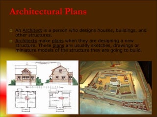
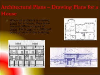
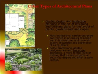
The document discusses various types of drawings used in architectural planning and building construction projects, including:
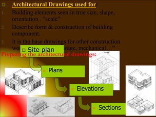
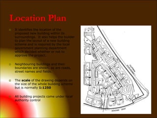
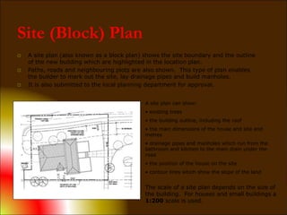
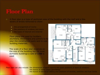
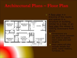
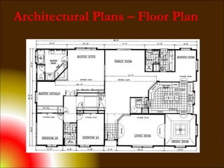
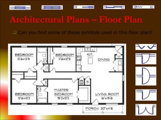
- Location plans, site plans, and floor plans which show the layout and dimensions of the building and property.
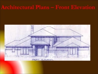
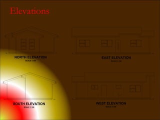
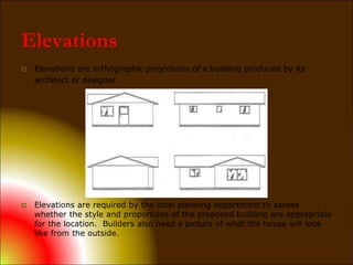
- Elevations which show the exterior surfaces of the building.
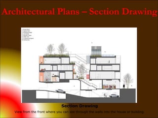
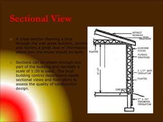
- Section drawings which show internal and external construction by cutting through walls and floors.
- Engineering, architectural, technical, shop, and "as-built" drawings which provide specifications for construction elements, fabrication, and recording changes made during construction.
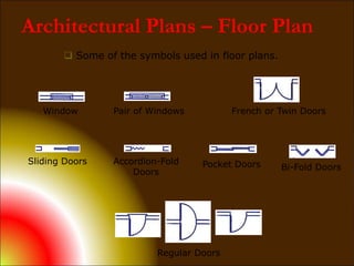
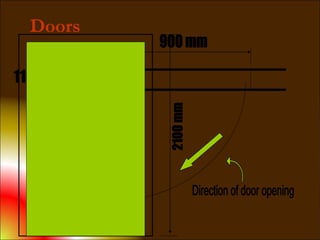
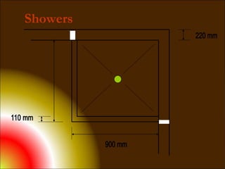
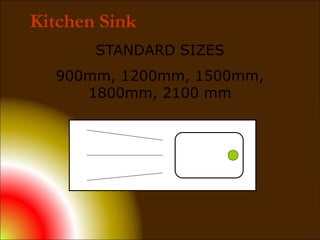
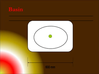
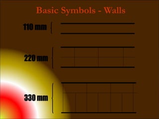
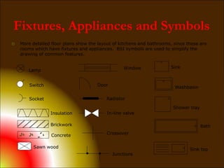
Standard symbols and conventions are used in floor plans, elevations, and sections to clearly convey construction elements and fixtures. Architectural drawings are essential for planning approval and effective coordination between builders and trades.