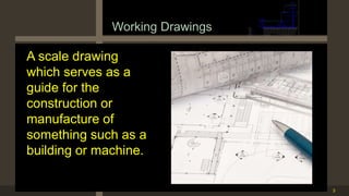
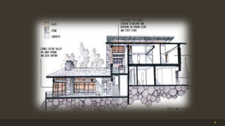
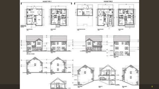
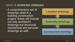
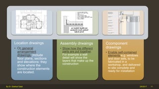
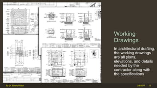
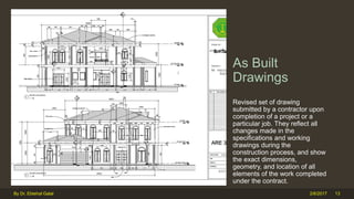
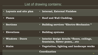
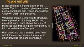
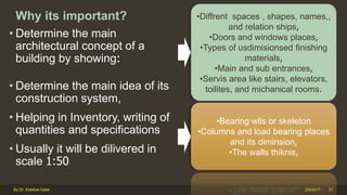
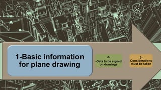
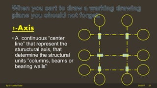
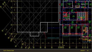
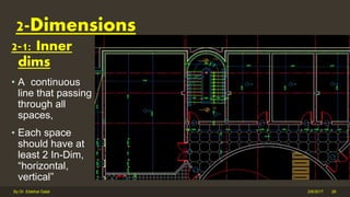
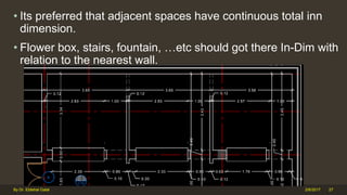
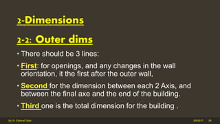
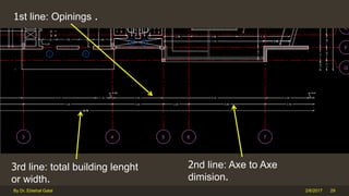
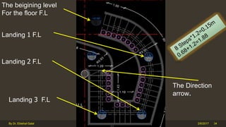
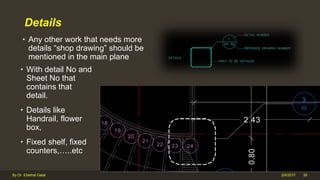
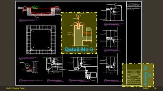
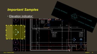
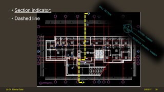
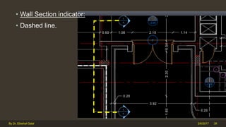
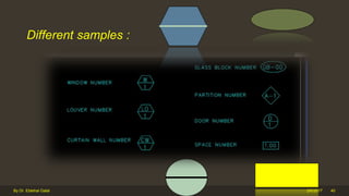
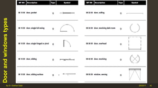
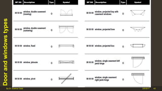
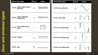
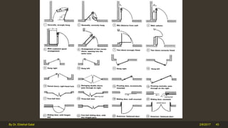
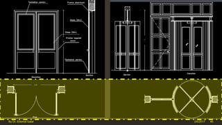
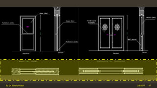
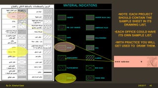
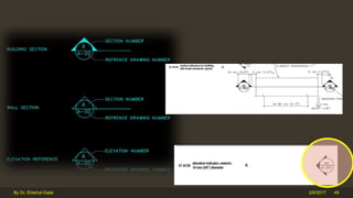
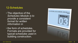
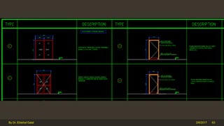
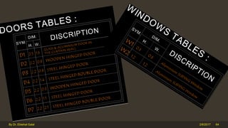
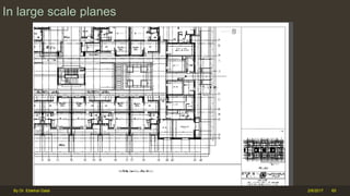
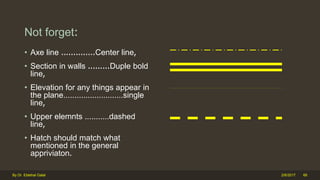
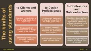
Introduction to working drawings course for architects and interior designers.
it contains 3 main parts:
1-general introduction to the course and its objectives and importance,
2-guide lines for plan drawings for beginners,
3-introduction to NCS.
This is a slide presentation of what an architect does, what are his roles in different stages of the construction industry and the types of drawings they produced.
A set of Working Drawings is a ‘construction manual’ describing accurate information of the designers intentions for construction, in a manner that is clearly expressed and easily understood to ensure on that wastes emanating from on site decision making are eliminated.
Architectural Design Process for Beginners/StudentsGary Gilson
This presentation is intended for Semester 2/3 Architecture students who are just stepping into Architectural design from Basic Design/Other generic preparatory subjects.
This is a step-by-step visual presentation on the Architectural Design Process followed in Architecture Schools (in India). The approach to design may vary and is subject to the respective School’s philosophy and methodology.
All drawings/models/renders/sketches are used only for educational purposes and the rights and ownership of these belong to the respective Architects/Designers.
it is about designing building by few articulation techniques, for example by altering its corners, or emphasizing its vertical, horizontal, base, roof, ceiling plane to add creativity.
the corners van be altered by cutting it, adding an element to it, curving it, opening it or even giving it a contrasting tone than the other surfaces.
this report talks about architect's as project managers, the services they tend to render, also the advantages of appointing an architect as a project manager..
Automobile Management System Project Report.pdfKamal Acharya
The proposed project is developed to manage the automobile in the automobile dealer company. The main module in this project is login, automobile management, customer management, sales, complaints and reports. The first module is the login. The automobile showroom owner should login to the project for usage. The username and password are verified and if it is correct, next form opens. If the username and password are not correct, it shows the error message.
When a customer search for a automobile, if the automobile is available, they will be taken to a page that shows the details of the automobile including automobile name, automobile ID, quantity, price etc. “Automobile Management System” is useful for maintaining automobiles, customers effectively and hence helps for establishing good relation between customer and automobile organization. It contains various customized modules for effectively maintaining automobiles and stock information accurately and safely.
When the automobile is sold to the customer, stock will be reduced automatically. When a new purchase is made, stock will be increased automatically. While selecting automobiles for sale, the proposed software will automatically check for total number of available stock of that particular item, if the total stock of that particular item is less than 5, software will notify the user to purchase the particular item.
Also when the user tries to sale items which are not in stock, the system will prompt the user that the stock is not enough. Customers of this system can search for a automobile; can purchase a automobile easily by selecting fast. On the other hand the stock of automobiles can be maintained perfectly by the automobile shop manager overcoming the drawbacks of existing system.
About
Indigenized remote control interface card suitable for MAFI system CCR equipment. Compatible for IDM8000 CCR. Backplane mounted serial and TCP/Ethernet communication module for CCR remote access. IDM 8000 CCR remote control on serial and TCP protocol.
• Remote control: Parallel or serial interface.
• Compatible with MAFI CCR system.
• Compatible with IDM8000 CCR.
• Compatible with Backplane mount serial communication.
• Compatible with commercial and Defence aviation CCR system.
• Remote control system for accessing CCR and allied system over serial or TCP.
• Indigenized local Support/presence in India.
• Easy in configuration using DIP switches.
Technical Specifications
Indigenized remote control interface card suitable for MAFI system CCR equipment. Compatible for IDM8000 CCR. Backplane mounted serial and TCP/Ethernet communication module for CCR remote access. IDM 8000 CCR remote control on serial and TCP protocol.
Key Features
Indigenized remote control interface card suitable for MAFI system CCR equipment. Compatible for IDM8000 CCR. Backplane mounted serial and TCP/Ethernet communication module for CCR remote access. IDM 8000 CCR remote control on serial and TCP protocol.
• Remote control: Parallel or serial interface
• Compatible with MAFI CCR system
• Copatiable with IDM8000 CCR
• Compatible with Backplane mount serial communication.
• Compatible with commercial and Defence aviation CCR system.
• Remote control system for accessing CCR and allied system over serial or TCP.
• Indigenized local Support/presence in India.
Application
• Remote control: Parallel or serial interface.
• Compatible with MAFI CCR system.
• Compatible with IDM8000 CCR.
• Compatible with Backplane mount serial communication.
• Compatible with commercial and Defence aviation CCR system.
• Remote control system for accessing CCR and allied system over serial or TCP.
• Indigenized local Support/presence in India.
• Easy in configuration using DIP switches.
Cosmetic shop management system project report.pdfKamal Acharya
Buying new cosmetic products is difficult. It can even be scary for those who have sensitive skin and are prone to skin trouble. The information needed to alleviate this problem is on the back of each product, but it's thought to interpret those ingredient lists unless you have a background in chemistry.
Instead of buying and hoping for the best, we can use data science to help us predict which products may be good fits for us. It includes various function programs to do the above mentioned tasks.
Data file handling has been effectively used in the program.
The automated cosmetic shop management system should deal with the automation of general workflow and administration process of the shop. The main processes of the system focus on customer's request where the system is able to search the most appropriate products and deliver it to the customers. It should help the employees to quickly identify the list of cosmetic product that have reached the minimum quantity and also keep a track of expired date for each cosmetic product. It should help the employees to find the rack number in which the product is placed.It is also Faster and more efficient way.
Sachpazis:Terzaghi Bearing Capacity Estimation in simple terms with Calculati...Dr.Costas Sachpazis
Terzaghi's soil bearing capacity theory, developed by Karl Terzaghi, is a fundamental principle in geotechnical engineering used to determine the bearing capacity of shallow foundations. This theory provides a method to calculate the ultimate bearing capacity of soil, which is the maximum load per unit area that the soil can support without undergoing shear failure. The Calculation HTML Code included.
Overview of the fundamental roles in Hydropower generation and the components involved in wider Electrical Engineering.
This paper presents the design and construction of hydroelectric dams from the hydrologist’s survey of the valley before construction, all aspects and involved disciplines, fluid dynamics, structural engineering, generation and mains frequency regulation to the very transmission of power through the network in the United Kingdom.
Author: Robbie Edward Sayers
Collaborators and co editors: Charlie Sims and Connor Healey.
(C) 2024 Robbie E. Sayers
Courier management system project report.pdfKamal Acharya
It is now-a-days very important for the people to send or receive articles like imported furniture, electronic items, gifts, business goods and the like. People depend vastly on different transport systems which mostly use the manual way of receiving and delivering the articles. There is no way to track the articles till they are received and there is no way to let the customer know what happened in transit, once he booked some articles. In such a situation, we need a system which completely computerizes the cargo activities including time to time tracking of the articles sent. This need is fulfilled by Courier Management System software which is online software for the cargo management people that enables them to receive the goods from a source and send them to a required destination and track their status from time to time.
COLLEGE BUS MANAGEMENT SYSTEM PROJECT REPORT.pdfKamal Acharya
The College Bus Management system is completely developed by Visual Basic .NET Version. The application is connect with most secured database language MS SQL Server. The application is develop by using best combination of front-end and back-end languages. The application is totally design like flat user interface. This flat user interface is more attractive user interface in 2017. The application is gives more important to the system functionality. The application is to manage the student’s details, driver’s details, bus details, bus route details, bus fees details and more. The application has only one unit for admin. The admin can manage the entire application. The admin can login into the application by using username and password of the admin. The application is develop for big and small colleges. It is more user friendly for non-computer person. Even they can easily learn how to manage the application within hours. The application is more secure by the admin. The system will give an effective output for the VB.Net and SQL Server given as input to the system. The compiled java program given as input to the system, after scanning the program will generate different reports. The application generates the report for users. The admin can view and download the report of the data. The application deliver the excel format reports. Because, excel formatted reports is very easy to understand the income and expense of the college bus. This application is mainly develop for windows operating system users. In 2017, 73% of people enterprises are using windows operating system. So the application will easily install for all the windows operating system users. The application-developed size is very low. The application consumes very low space in disk. Therefore, the user can allocate very minimum local disk space for this application.
Final project report on grocery store management system..pdfKamal Acharya
In today’s fast-changing business environment, it’s extremely important to be able to respond to client needs in the most effective and timely manner. If your customers wish to see your business online and have instant access to your products or services.
Online Grocery Store is an e-commerce website, which retails various grocery products. This project allows viewing various products available enables registered users to purchase desired products instantly using Paytm, UPI payment processor (Instant Pay) and also can place order by using Cash on Delivery (Pay Later) option. This project provides an easy access to Administrators and Managers to view orders placed using Pay Later and Instant Pay options.
In order to develop an e-commerce website, a number of Technologies must be studied and understood. These include multi-tiered architecture, server and client-side scripting techniques, implementation technologies, programming language (such as PHP, HTML, CSS, JavaScript) and MySQL relational databases. This is a project with the objective to develop a basic website where a consumer is provided with a shopping cart website and also to know about the technologies used to develop such a website.
This document will discuss each of the underlying technologies to create and implement an e- commerce website.
Vaccine management system project report documentation..pdfKamal Acharya
The Division of Vaccine and Immunization is facing increasing difficulty monitoring vaccines and other commodities distribution once they have been distributed from the national stores. With the introduction of new vaccines, more challenges have been anticipated with this additions posing serious threat to the already over strained vaccine supply chain system in Kenya.
CFD Simulation of By-pass Flow in a HRSG module by R&R Consult.pptxR&R Consult
CFD analysis is incredibly effective at solving mysteries and improving the performance of complex systems!
Here's a great example: At a large natural gas-fired power plant, where they use waste heat to generate steam and energy, they were puzzled that their boiler wasn't producing as much steam as expected.
R&R and Tetra Engineering Group Inc. were asked to solve the issue with reduced steam production.
An inspection had shown that a significant amount of hot flue gas was bypassing the boiler tubes, where the heat was supposed to be transferred.
R&R Consult conducted a CFD analysis, which revealed that 6.3% of the flue gas was bypassing the boiler tubes without transferring heat. The analysis also showed that the flue gas was instead being directed along the sides of the boiler and between the modules that were supposed to capture the heat. This was the cause of the reduced performance.
Based on our results, Tetra Engineering installed covering plates to reduce the bypass flow. This improved the boiler's performance and increased electricity production.
It is always satisfying when we can help solve complex challenges like this. Do your systems also need a check-up or optimization? Give us a call!
Work done in cooperation with James Malloy and David Moelling from Tetra Engineering.
More examples of our work https://www.r-r-consult.dk/en/cases-en/
10. WHAT IS WORKING DRWAING
• A comprehensive set of
drawings used in a
building construction
project: these will include
not only architect's
drawings but structural,
mechanical and services
drawings as well. Ccomponent drawings
Assembly drwaings
Location drwaings
2/6/2017 10By Dr. Ebtehal Galal
11. Location drwaings
• Or general
arrangement
drawings, include
floor plans, sections
and elevations: they
show where the
construction elements
are located.
Assembly drwaings
• Show how the different
parts are put together.
For example a wall
detail will show the
layers that make up the
construction
Ccomponent
drawings
• Enable self-contained
elements e.g. windows
and door sets, to be
fabricated in a
workshop, and delivered
to site complete and
ready for installation
2/6/2017 11By Dr. Ebtehal Galal
12. Working
Drawings
In architectural drafting,
the working drawings
are all plans,
elevations, and details
needed by the
contractor along with
the specifications
2/6/2017By Dr. Ebtehal Galal 12
13. As Built
Drawings
Revised set of drawing
submitted by a contractor upon
completion of a project or a
particular job. They reflect all
changes made in the
specifications and working
drawings during the
construction process, and show
the exact dimensions,
geometry, and location of all
elements of the work completed
under the contract.
2/6/2017By Dr. Ebtehal Galal 13
14. Course objectives
14
JUMA HUSSAIN
Eng , M BAAL BAKI
T YPICAL FL OOR PL AN
JUMA HUSSAIN
Eng , M BAAL BAKI
GROUN DFL OOR PL AN
JUMA HUSSAIN
Eng , M BAAL BAKI
BASE MEN T FL OOR PL AN
JUMA HUSSAIN
Eng , M BAAL BAKI
MEZ Z ANE EN FL OOR PL AN
JUMA HUSSAIN
Eng , M BAAL BAKI
T YPICAL FL OOR PL AN
JUMA HUSSAIN
Eng , M BAAL BAKI
T YPICAL FL OOR PL AN
• How to start your project
• Different types of architectural drawings
• The importance of each stage
• Common mistakes
• Reading others spec drawings
15. List of drawing contains:
15
• Layouts and site plan • Internal, External Finishes
• Planes • Roof and Wall Cladding,
• Sections • Building services “Electro-Mechanics ”
• Elevations • Building systems
• Windows - Doors • Interior design details “floors, ceilings,
fountains, flower poxes,…etc
• Stairs • Vegetation, lighting and landscape works
Coordination
20. • Is presented as if looking down on the
space. The most common plan view is the
architectural floor plan, which shows doors,
windows, walls, and partitions.
• Variations of plan views include structural,
fire suppression, plumbing, HVAC, and
electrical plans. Each shows the work of
the respective trades in plan view as they fit
into the architectural floor plan.
• Plan views are also a starting point from
which the architect directs the reader to
other drawings for more information.
2/6/2017By Dr. Ebtehal Galal 20
21. Why its important?
• Determine the main
architectural concept of a
building by showing:
• Determine the main idea of its
construction system,
• Helping in Inventory, writing of
quantities and specifications
• Usually it will be dilivered in
scale 1:50
2/6/2017By Dr. Ebtehal Galal 21
•Diffrent spaces , shapes, names,,
and relation ships,
•Doors and windows places,
•Types of usdimisionsed finishing
materials,
•Main and sub entrances,
•Servis area like stairs, elevators,
toilites, and michanical rooms.
•Bearing wlls or skeleton
•Columns and load bearing places
and its diminsion,
•The walls thiknis,
22. 2/6/2017By Dr. Ebtehal Galal 22
1-Basic information
for plane drawing
2-
-Data to be signed
on drawings
3-
Considerations
must be taken
23. 1-Axis
• A continuous “center
line” that represent the
stuructural axis, that
determine the structural
units ”columns, beams or
bearing walls“
2/6/2017By Dr. Ebtehal Galal 23
24. • Each axe got it name “No
or Alpha”
• When each?
• If you needed to ad sub
axe then use / , like A/
and some times it A*,
• For tilted axis use a
combination between
both No and Alpha
2/6/2017By Dr. Ebtehal Galal 24
26. 2-1: Inner
dims
• A continuous
line that passing
through all
spaces,
• Each space
should have at
least 2 In-Dim,
“horizontal,
vertical”
2/6/2017By Dr. Ebtehal Galal 26
2-Dimensions
27. • Its preferred that adjacent spaces have continuous total inn
dimension.
• Flower box, stairs, fountain, …etc should got there In-Dim with
relation to the nearest wall.
2/6/2017By Dr. Ebtehal Galal 27
28. 2-2: Outer dims
• There should be 3 lines:
• First: for openings, and any changes in the wall
orientation, it the first after the outer wall,
• Second for the dimension between each 2 Axis, and
between the final axe and the end of the building.
• Third one is the total dimension for the building .
2/6/2017By Dr. Ebtehal Galal 28
2-Dimensions
29. 2/6/2017By Dr. Ebtehal Galal 29
1st line: Opinings .
3rd line: total building lenght
or width.
2nd line: Axe to Axe
dimision.
30. • 6mm (scale 1:50) circle that indicate the finishing floor
level in typical floor, and the slab surface for the roof….
Why???.
2/6/2017By Dr. Ebtehal Galal 30
3-levels
31. • Any changing in levels “ stairs, steps, ramps” should
have 2 level sample before and after the changes.
• Its important also not to forget the direction arrow.
2/6/2017By Dr. Ebtehal Galal 31
32. 2/6/2017By Dr. Ebtehal Galal 32
1-Basic information for
plane drawing
2--Data to be signed
on drawings
3-Considerations
must be taken
33. Stairs Steps No and dashed line
• Start with 1…..
2/6/2017By Dr. Ebtehal Galal 33
34. 2/6/2017By Dr. Ebtehal Galal 34
The Direction
arrow.
The beigining level
For the floor F.L
Landing 1 F.L
Landing 2 F.L
Landing 3 F.L
35. Details
• Any other work that needs more
details “shop drawing” should be
mentioned in the main plane
2/6/2017By Dr. Ebtehal Galal 35
• With detail No and
Sheet No that
contains that
detail.
• Details like
Handrail, flower
box,
• Fixed shelf, fixed
counters,…..etc
50. 2/6/2017By Dr. Ebtehal Galal 50
1-Basic information for
plane drawing
2-Data to be signed on
drawings
3-
consideratio
ns must be
taken
51. • That determine building
orientation ,
• It could be in different
shape.
• And it placed with each
plane in the border.
2/6/2017By Dr. Ebtehal Galal 51
4- North direction
53. 2/6/2017By Dr. Ebtehal Galal 53
Curves
The Virtical dimision
from the center to the
nearest Axe.
The Curve center
The Horizontaldimision
from the center to the
nearest Axe.
The Curve Radius .
55. 2/6/2017By Dr. Ebtehal Galal 55
Angles
The Virtical dimision
from the center to the
nearest Axe.
The Curve center
The Horizontaldimision
from the center to the
nearest Axe.
The Curve Radius .
3.5m
56. -Finishing materials indicators
and Space name
• Each space shoul get
its own name,
• With description of its
finishing materials for
walls, floor, skirting,
and cieling .
2/6/2017By Dr. Ebtehal Galal 56
58. 12-Schedules
• The objective of the
Schedules Module is to
provide a consistent
format for written
information in
• the form of schedules.
Formats are provided for
typical schedules used in
building construction.
2/6/2017By Dr. Ebtehal Galal 58
59. 12-1: Finishing Materials Schedule
• It could take different
shapes.
• It is the easiest way to
identify all finishing.
2/6/2017By Dr. Ebtehal Galal 59
66. Not forget:
• Axe line ..............Center line,
• Section in walls .........Duple bold
line,
• Elevation for any things appear in
the plane...........................single
line,
• Upper elemnts ...........dashed
line,
• Hatch should match what
mentioned in the general
appriviaton.
2/6/2017By Dr. Ebtehal Galal 66
71. • Everything you will need to assemble a concise set of documents
/drawings for the built environment.
• It is a guide to what is required by todays Computer Aided Design
software tools to create the necessary documentation for construction.
• It includes: Layering standards, symbols, line styles, document
formatting, abbreviations, and everything needed to present your
design in an easy to understand standard for construction.
• This will result in reducing the costs of developing and maintaining
individual office standards, and transferring building data from design
applications to facility management applications.
•
2/6/2017 71By Dr. Ebtehal Galal
72. 2/6/2017By Dr. Ebtehal Galal 72
https://www.youtube.com/watch?v=5-DrHhWROxU
https://www.nationalcadstandard.org/ncs6/ordering.php
73. to Clients and
Owners
Consistent organization of
data for all projects, from
all sources.
Greater clarity of
communication of design
intent to the client.
Streamlined construction
document checking
process.
to Design
Professionals
Consistent data classification
for all projects, regardless of
the project type or client.
Seamless transfer of
information among architects,
engineers, and other design
team members.
Reduced staff training time to
teach "office standards."
to Contractors
and
Subcontractors
Consistent drawing sheet
order and sheet
organization; information
appears in the same place
in all drawing sets.
Consistent detail reference
system.
Consistent organization of
data for all projects, from
all sources.
2/6/2017 73By Dr. Ebtehal Galal
Editor's Notes
http://en.wikipedia.org/wiki/Architectural_drawing#Working_drawings
Location drawings, also called
Assembly drawings, how they are fixed to structural elements, how to finish the edges of openings, and how prefabricated components are to be fitted.
Component drawings. Larger components may include roof trusses, cladding panels, cupboards and kitchens. Complete rooms, especially hotel bedrooms and bathrooms, may be made as prefabricated pods complete with internal decorations and fittings.
Traditionally, working drawings would typically combine plans, sections, elevations and some details to provide a complete explanation of a building on one sheet. That was possible because little detail was included, the building techniques involved being common knowledge amongst building professionals. Modern working drawings are much more detailed and it is standard practice to isolate each view on a separate sheet. Notes included on drawings are brief, referring to standardised specification documents for more information. Understanding the layout and construction of a modern building involves studying an often-sizeable set of drawings and documents.
neufert3th
Auol-working-lectures-doors
building owners and building design and construction professionals faced the difficulty of comprehending and organizing electronic building design data produced in a multitude of formats.