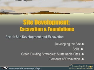
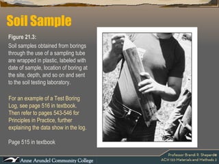
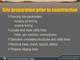
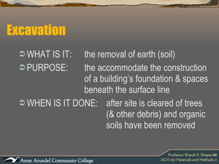
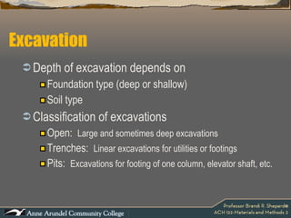
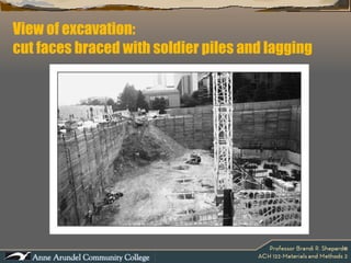
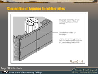
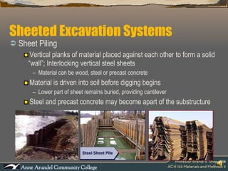
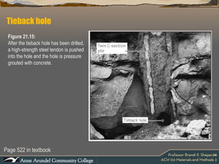
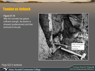
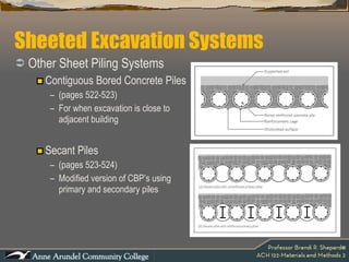
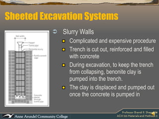
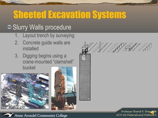
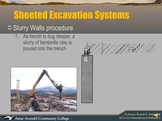
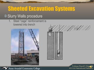
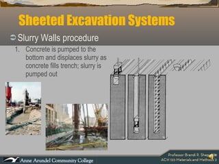
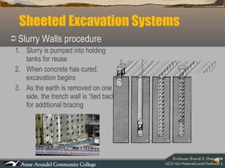
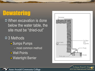
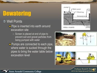
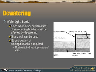
Site Development:  Excavation & Foundations
Site Development:  Excavation & Foundations Part 1: Site Development and Excavation Developing the Site  Soils     Green Building Strategies: Sustainable Sites   Elements of Excavation  
Developing the Site Buildings do not exist in isolation. They are conceived to house and support a range of human activities in response to sociocultural, economic, and political needs, and erected in natural and built environments that constrain as well as offer opportunities for development.  We should therefore carefully consider the environmental forces that a building site presents in planning the design and construction of buildings.  Frank Ching,  Building Construction Illustrated, 3 rd  ed.
Developing the Site Soil Topography Grade & Slope Protection Plants & Trees Solar Radiation and Orientation Site Drainage Wind Zoning Ordinances Site Access & Circulation Pedestrian Circulation Vehicular Circulation & Parking Utilities  (electrical, water, gas, communication) Hardscaping and Impervious Surfaces Sustainable Strategies Elements to consider:
Developing the Site Site Analysis  must be performed to evaluate the data presented by these elements.  Site Analysis is the process of studying the contextual forces that influence how we might situate a building, lay out and orient its spaces, shape and articulate its enclosure, and establish its relationship to the landscape.  Any site survey begins with the gathering of physical site data.  Frank Ching,  Building Construction Illustrated, 3 rd  ed .
Soil All buildings rely on  soil   for their ultimate support. The underlying foundation is effected by the soil’s  strength under loading.
Soil The measure of a soil’s strength is its bearing capacity in pounds per square foot (psi).  Factors that determine the bearing capacity of a soil are:    stratification (classification)   composition    density of soil bed   water    freezing/thawing   permeability    variations of particle size
Soil Types Affects the type and size of a building’s foundation system Affects the drainage of ground and surface water Affects the types of plant material able to grow on a site
Soil Types ROCK Continuous  mass of earth mineral  are firmly  bonded together Removal by blasting or drilling Located beneath layer(s) of soil Strongest and most stable of “soil” that a  structure can be supported
Soil Types SOIL Unconsolidated mineral  particles  or conglomerates located at the top layer of the earth’s crust Removal by lifting or digging Boulder: two hands or heavy equipment to lift Cobble: one hand to lift Gravel: pinch between fingers Sand: flows through fingers
Soil Types SILT Granules are equal in size and diameter Range in size .002 to .00008 inch Found mostly on river beds and close to waterways Highly susceptible to frost action Poor permeability and drainage Bearing capacity of 2000 psf Frictional/Cohesionless: “loose”
Soil Types CLAY Particles are plate-shaped Range in size less than .00008 inch Very close in characteristics to SILT Cohesive: “sticks together” Does not easily “cave-in”
Soil Types ORGANIC SOILS  Peat, topsoil High content of organic matter (plants) Spongy & compress easily Slightly susceptible to frost action Poor permeability and drainage Great for the perennials, unsuitable for foundations Organic soils consist of fully or partially decayed plant matter, compressive and unsuitable for foundations
Soil Types STRADA Superimposed layers of different soils Mixtures of several different soils Silty-gravels Gravelly sands Clayey sands Silty clays
Soil Stratification (classification) Particle size Coarse grained (gravel & sand) Fine grained (silt & clay) Particle shape Spherical or ellipsoidal, shaped by mechanical weathering Gravel, sand & silt Flat, plate-like, large surface area to volume ratio Behavior influenced by electrostatic forces and presence of water Cohesion Cohesive soils are  fine grained and particles are attracted to each other in the presence of water. Non-cohesive soils are course grained and are not attracted to each other
Soil characteristics by particle size coarse-grained cobbles 60mm coarse gravel 19mm fine gravel 5.5mm coarse sand 2.0mm medium sand 0.6mm fine sand 0.08mm fine-grained silt  > .08mm clay  > .08mm A sieve is an open top container with a wire mesh bottom used for screening particles.  The are used to analyze particle size distribution of soils & concrete aggregates.
Soil Types
Additional factors of Soil Stability How a soil will retain water Rock, gravel, sands are more stable soils Clay is considerably unstable Swells when water is absorbed Dries when water is squeezed and evaporated
Additional factors of Soil Drainage How water withdraws from the soil Water passes easily through gravels & sands Water passes slowly through silts & fine sands Water is absorbed by clay
How do we know what type of soil is best? Perform a Soil Test Penometer Test Weight is dropped on rod and distance into soil is measured Test Pits Small excavations to observe soil, adjacent conditions and take samples Soil Borings Core sample, drilled into the earth, sample removed and analyzed. Each layer is analyzed and calculations for bearing capacity are made
Soil sampling and testing Soil sampling Test pit method Test boring method Also allows for standard penetration test on site Laboratory testing Sieve analysis Determines particle size distribution Soil classification Moisture content Dry density Liquid limit, plastic limit Compressive strength Shear strength
Test Boring Equipment Page 514 in textbook Figure 21.2 Picture A:  truck-mounted drilling machine boring a hole in the ground with a cutting tip at the end of a hollow pipe stem.  During the drilling operation, compressed air is pushed through the hollow stem to suck the drilled soil out to keep the boring clean.  Picture B:  A hollow pipe stem with a typical cutting bit.
Page 515 in textbook Soil Sample Figure 21.3:  Soil samples obtained from borings through the use of a sampling tube are wrapped in plastic, labeled with date of sample, location of boring at the site, depth, and so on and sent to the soil testing laboratory.  For an example of a Test Boring Log, see page 516 in textbook. Then refer to pages 543-546 for Principles in Practice, further explaining the data show in the log.
Site preparation prior to construction Fencing site parameters including silt fencing property fencing  Locate and mark utility lines Water, gas, electrical, communication Demolish unneeded structures and utility lines Remove trees, brush, topsoil, debris Prepare staging area
LEED: Leadership in Energy and Environmental Design GREEN BUILDING STRATEGIES Prerequisite 1:  REQUIRED Construction Activity Pollution Prevention Intent To reduce pollution from construction activities by controlling soil erosion, waterway sedimentation and airborne dust generation. Requirements Create and implement an erosion and sedimentation control plan for all construction activities associated with  the project. Potential Technologies & Strategies Create an erosion and sedimentation control plan during the design phase of the project. Consider employing strategies such as temporary and permanent seeding, mulching, earthen dikes, silt fencing, sediment traps and sediment basins. Category:  Sustainable Sites
LEED: Leadership in Energy and Environmental Design GREEN BUILDING STRATEGIES Credit 1:  1 point Site Selection Intent To avoid the development of inappropriate sites and reduce the environmental impact from the location of a building on a site. Category:  Sustainable Sites
LEED: Leadership in Energy and Environmental Design GREEN BUILDING STRATEGIES Credit 1:  1 point Site Selection Requirements Do not develop buildings, hardscape, roads or parking areas on portions of sites that meet any of the following criteria: Prime farmland as defined by the U.S.D.A. Previously undeveloped land whose elevation is lower than 5 feet above the elevation of the 100-year flood as defined by FEMA Land specifically identified as habitat for any species on federal or state threatened or endangered lists Category:  Sustainable Sites
LEED: Leadership in Energy and Environmental Design GREEN BUILDING STRATEGIES Credit 1:  1 point Site Selection Requirements Do not develop buildings, hardscape, roads or parking areas on portions of sites that meet any of the following criteria: Land within 100 feet of any wetlands Previously undeveloped land that is within 50 feet of a water body, defined as seas, lakes, rivers, streams and tributaries that support or could support fish, recreation or industrial use, consistent with the terminology of the Clean Water Act Land that prior to acquisition for the project was public parkland, unless land of equal or greater value as parkland is accepted in trade by the public landowner Category:  Sustainable Sites
LEED: Leadership in Energy and Environmental Design GREEN BUILDING STRATEGIES Credit 1:  1 point Site Selection Potential Technologies & Strategies During the site selection process, give preference to sites that do not include sensitive elements or restrictive land types.  Select a suitable building location and design the building with a minimal footprint to minimize disruption of the environmentally sensitive areas identified above. Category:  Sustainable Sites
LEED: Leadership in Energy and Environmental Design GREEN BUILDING STRATEGIES Credit 2:  5 points Development Density and Community Connectivity Intent To channel development to urban areas with existing infrastructure, protect greenfields, and preserve habitat and natural resources. Requirements Option #1: Development Density Option #2: Community Connectivity  Potential Technologies & Strategies During the site selection process, give preference to urban sites with pedestrian access to a variety of services Category:  Sustainable Sites
LEED: Leadership in Energy and Environmental Design GREEN BUILDING STRATEGIES Credit 3:  1 point Brownfield Development Intent To rehabilitate damaged sites where development is complicated by environmental contamination and to reduce pressure on undeveloped land. Requirements Option #1: Develop a contaminated site Option #2: Develop on a site defined as brownfield by AHJ Potential Technologies & Strategies During the site selection process, give preference to brownfield sites. Identify tax incentives and property cost savings. Coordinate site development plans with remediation activity, as appropriate. Category:  Sustainable Sites
LEED: Leadership in Energy and Environmental Design GREEN BUILDING STRATEGIES Credit 4.1:  6 points Alternative Transportation – Public Transportation Access Credit 4.2:  1 point Alternative Transportation – Bicycle Storage & Changing Rooms Credit 4.3:  3 points Alternative Transportation – Low-Emitting and Fuel Efficient Veh. Credit 4.4:  2 points Alternative Transportation – Parking Capacity Category:  Sustainable Sites
LEED: Leadership in Energy and Environmental Design GREEN BUILDING STRATEGIES Credit 5.1:  1 point Site Development – Protect or Restore Habitat Intent To conserve existing natural area and restore damaged areas to provide habitat and promote biodiversity.  Requirements Case #1: Greenfield Sites Case #2: Previously Developed Areas or Graded Sites Potential Technologies & Strategies Greenfield site survey to identify minimal disruption to existing ecosystems and minimize building footprint.  Category:  Sustainable Sites
LEED: Leadership in Energy and Environmental Design GREEN BUILDING STRATEGIES Credit 5.2:  1 point Site Development – Maximize Open Space Credit 6.1:  1 point Stormwater Design – Quality Control (Impervious Surface) Credit 6.2:  1 point Stormwater Design – Quality Control (Stormwater runoff) Credit 7.1:  1 point Heat Island Effect – Nonroof (Site Hardscaping) Credit 7.2:  1 point Heat Island Effect – Roof  Credit 8:  1 point Light Pollution Reduction Category:  Sustainable Sites
Excavation WHAT IS IT:  the removal of earth (soil) PURPOSE: the accommodate the construction  of a building’s foundation & spaces  beneath the surface line WHEN IS IT DONE: after site is cleared of trees  (& other debris) and organic  soils have been removed
Depth of excavation depends on  Foundation type (deep or shallow) Soil type Classification of excavations Open:  Large and sometimes deep excavations Trenches:  Linear excavations for utilities or footings Pits:  Excavations for footing of one column, elevator shaft, etc. Excavation
Types of  Open  Excavation BENCHED Excavation Tiered or sloped back Soil will not slide back into hole Steep for cohesive soils Shallow for frictional soils Type is done on large, spacious sites
Uniform slope & stepped excavations.  Used when adequate space is available on site. Page 518 in textbook Figure 21.8 Two alternatives used for open excavations
Types of Open Excavation SHEETED Excavation Temporary vertical wall supports that hold back earth Several methods can be used Sheeting is supported from earth and water pressure Driving into soil enough to act as a cantilever Bracing the sheeting  Type is used in urban sites
Soldier Beams & Lagging Wide-flanged steel “columns” driven into earth before digging As earth is removed, horizontal wooden planks are placed in between steel “columns” (Lagging) Sheeted Excavation Systems
View of excavation:  cut faces braced with soldier piles and lagging
Connection of lagging to soldier piles Page 522 in textbook Figure 21.16
 
Sheeted Excavation Systems Sheet Piling Vertical planks of material placed against each other to form a solid “wall”; Interlocking vertical steel sheets Material can be wood, steel or precast concrete Material is driven into soil before digging begins Lower part of sheet remains buried, providing cantilever Steel and precast concrete may become apart of the substructure
Profile of steel sheet piles Page 519 in textbook Figure 21.9:  Steel sheet piles with a Z-shaped profile. Adjacent sections interlock with each other. Several other sectional profiles are available.  Figure 21.10:  Steel sheet piles being driven into the soil using a diesel pile drive.
Sheeted Excavation Systems
Bracing Systems Crosslot Bracing Uses vertical and horizontal wide-flanged steel Vertical steel is driven into unexcavated earth As earth is removed, horizontal struts are laid against beams at sheeting face (whalers)
Bracing Systems Rakers Diagonal bracing against sheeting wall Rakers are set against whalers and bear against heel blocks Earth removal is challenging because a clamshell bucket has to be used
Bracing Systems Tiebacks Like “nailing” into the soil Drill bores hole thru sheeting and into soil Steel cables (tendons) are inserted into holes & filled with grout-substance for anchorage Tendons are stretched tight with hydraulic jacks Tendons are fastened to whalers
Section through excavation with soldier piles and lagging Page 521 in textbook Figure 21.13:  A section through an excavation supported by soldier piles and lagging. Tiebacks are installed as the excavation proceeds.  This is followed by bolting the lagging to solider piles. The number of tiebacks required is a function of the depth of excavation and the type of soil.
Drilling for tiebacks Page 521 in textbook Figure 21.14:  Drilling of a tieback hole in progress.
Close-up:  drilling for tiebacks Page 521 in textbook Figure 21.14:  Close-up of the same operation. Note that the hole is drilled in the space between the twin C-sections of the piles. The concrete around the sections is lean (weak) to allow easier drilling.
Tieback hole Page 522 in textbook Figure 21.15:  After the tieback hole has been drilled, a high-strength steel tendon is pushed into the hole and the hole is pressure grouted with concrete.
Tendon as tieback Page 522 in textbook Figure 21.15:  After the concrete has gained sufficient strength, the tendon is stressed (posttensioned) and then anchored to the pile.
Sheeted Excavation Systems Other Sheet Piling Systems Contiguous Bored Concrete Piles  (pages 522-523) For when excavation is close to adjacent building Secant Piles  (pages 523-524) Modified version of CBP’s using primary and secondary piles
Sheeted Excavation Systems Slurry Walls Complicated and expensive procedure Trench is cut out, reinforced and filled with concrete During excavation, to keep the trench from collapsing, benonite clay is pumped into the trench. The clay is displaced and pumped out once the concrete is pumped in
Sheeted Excavation Systems Slurry Walls procedure Layout trench by surveying Concrete guide walls are installed Digging begins using a crane-mounted “clamshell” bucket
Sheeted Excavation Systems Slurry Walls procedure As trench is dug deeper, a slurry of bentonite clay is poured into the trench
Sheeted Excavation Systems Slurry Walls procedure Steel “cage” reinforcement is lowered into trench
Sheeted Excavation Systems Slurry Walls procedure Concrete is pumped to the bottom and displaces slurry as concrete fills trench; slurry is pumped out
Sheeted Excavation Systems Slurry Walls procedure Slurry is pumped into holding tanks for reuse When concrete has cured, excavation begins As the earth is removed on one side, the trench wall is “tied back” for additional bracing
 
Dewatering When excavation is done below the water table, the site must be “dried-out” 3 Methods Sumps Pumps most common method Well Points Watertight Barrier
Well Points Pipe is inserted into earth around excavation site Screen is placed at end of pipe to prevent soil and gravel particles from being pumped with water Pumps are connected to each pipe, where water is sucked through the pipes to bring the water table below excavation level Dewatering
Watertight Barrier  Used when other substructure of surrounding buildings will be affected by dewatering Slurry wall can be used Strong system of bracing/tiebacks is required Must resist hydrostatic pressure of water Dewatering
Next Lecture, Part 2- Foundations

ACH 122 Lecture 04a (Excavation & Foundations P1)

  • 1.
    Site Development: Excavation & Foundations
  • 2.
    Site Development: Excavation & Foundations Part 1: Site Development and Excavation Developing the Site  Soils  Green Building Strategies: Sustainable Sites  Elements of Excavation 
  • 3.
    Developing the SiteBuildings do not exist in isolation. They are conceived to house and support a range of human activities in response to sociocultural, economic, and political needs, and erected in natural and built environments that constrain as well as offer opportunities for development. We should therefore carefully consider the environmental forces that a building site presents in planning the design and construction of buildings. Frank Ching, Building Construction Illustrated, 3 rd ed.
  • 4.
    Developing the SiteSoil Topography Grade & Slope Protection Plants & Trees Solar Radiation and Orientation Site Drainage Wind Zoning Ordinances Site Access & Circulation Pedestrian Circulation Vehicular Circulation & Parking Utilities (electrical, water, gas, communication) Hardscaping and Impervious Surfaces Sustainable Strategies Elements to consider:
  • 5.
    Developing the SiteSite Analysis must be performed to evaluate the data presented by these elements. Site Analysis is the process of studying the contextual forces that influence how we might situate a building, lay out and orient its spaces, shape and articulate its enclosure, and establish its relationship to the landscape. Any site survey begins with the gathering of physical site data. Frank Ching, Building Construction Illustrated, 3 rd ed .
  • 6.
    Soil All buildingsrely on soil for their ultimate support. The underlying foundation is effected by the soil’s strength under loading.
  • 7.
    Soil The measureof a soil’s strength is its bearing capacity in pounds per square foot (psi). Factors that determine the bearing capacity of a soil are:  stratification (classification)  composition  density of soil bed  water  freezing/thawing  permeability  variations of particle size
  • 8.
    Soil Types Affectsthe type and size of a building’s foundation system Affects the drainage of ground and surface water Affects the types of plant material able to grow on a site
  • 9.
    Soil Types ROCKContinuous mass of earth mineral are firmly bonded together Removal by blasting or drilling Located beneath layer(s) of soil Strongest and most stable of “soil” that a structure can be supported
  • 10.
    Soil Types SOILUnconsolidated mineral particles or conglomerates located at the top layer of the earth’s crust Removal by lifting or digging Boulder: two hands or heavy equipment to lift Cobble: one hand to lift Gravel: pinch between fingers Sand: flows through fingers
  • 11.
    Soil Types SILTGranules are equal in size and diameter Range in size .002 to .00008 inch Found mostly on river beds and close to waterways Highly susceptible to frost action Poor permeability and drainage Bearing capacity of 2000 psf Frictional/Cohesionless: “loose”
  • 12.
    Soil Types CLAYParticles are plate-shaped Range in size less than .00008 inch Very close in characteristics to SILT Cohesive: “sticks together” Does not easily “cave-in”
  • 13.
    Soil Types ORGANICSOILS Peat, topsoil High content of organic matter (plants) Spongy & compress easily Slightly susceptible to frost action Poor permeability and drainage Great for the perennials, unsuitable for foundations Organic soils consist of fully or partially decayed plant matter, compressive and unsuitable for foundations
  • 14.
    Soil Types STRADASuperimposed layers of different soils Mixtures of several different soils Silty-gravels Gravelly sands Clayey sands Silty clays
  • 15.
    Soil Stratification (classification)Particle size Coarse grained (gravel & sand) Fine grained (silt & clay) Particle shape Spherical or ellipsoidal, shaped by mechanical weathering Gravel, sand & silt Flat, plate-like, large surface area to volume ratio Behavior influenced by electrostatic forces and presence of water Cohesion Cohesive soils are fine grained and particles are attracted to each other in the presence of water. Non-cohesive soils are course grained and are not attracted to each other
  • 16.
    Soil characteristics byparticle size coarse-grained cobbles 60mm coarse gravel 19mm fine gravel 5.5mm coarse sand 2.0mm medium sand 0.6mm fine sand 0.08mm fine-grained silt > .08mm clay > .08mm A sieve is an open top container with a wire mesh bottom used for screening particles. The are used to analyze particle size distribution of soils & concrete aggregates.
  • 17.
  • 18.
    Additional factors ofSoil Stability How a soil will retain water Rock, gravel, sands are more stable soils Clay is considerably unstable Swells when water is absorbed Dries when water is squeezed and evaporated
  • 19.
    Additional factors ofSoil Drainage How water withdraws from the soil Water passes easily through gravels & sands Water passes slowly through silts & fine sands Water is absorbed by clay
  • 20.
    How do weknow what type of soil is best? Perform a Soil Test Penometer Test Weight is dropped on rod and distance into soil is measured Test Pits Small excavations to observe soil, adjacent conditions and take samples Soil Borings Core sample, drilled into the earth, sample removed and analyzed. Each layer is analyzed and calculations for bearing capacity are made
  • 21.
    Soil sampling andtesting Soil sampling Test pit method Test boring method Also allows for standard penetration test on site Laboratory testing Sieve analysis Determines particle size distribution Soil classification Moisture content Dry density Liquid limit, plastic limit Compressive strength Shear strength
  • 22.
    Test Boring EquipmentPage 514 in textbook Figure 21.2 Picture A: truck-mounted drilling machine boring a hole in the ground with a cutting tip at the end of a hollow pipe stem. During the drilling operation, compressed air is pushed through the hollow stem to suck the drilled soil out to keep the boring clean. Picture B: A hollow pipe stem with a typical cutting bit.
  • 23.
    Page 515 intextbook Soil Sample Figure 21.3: Soil samples obtained from borings through the use of a sampling tube are wrapped in plastic, labeled with date of sample, location of boring at the site, depth, and so on and sent to the soil testing laboratory. For an example of a Test Boring Log, see page 516 in textbook. Then refer to pages 543-546 for Principles in Practice, further explaining the data show in the log.
  • 24.
    Site preparation priorto construction Fencing site parameters including silt fencing property fencing Locate and mark utility lines Water, gas, electrical, communication Demolish unneeded structures and utility lines Remove trees, brush, topsoil, debris Prepare staging area
  • 25.
    LEED: Leadership inEnergy and Environmental Design GREEN BUILDING STRATEGIES Prerequisite 1: REQUIRED Construction Activity Pollution Prevention Intent To reduce pollution from construction activities by controlling soil erosion, waterway sedimentation and airborne dust generation. Requirements Create and implement an erosion and sedimentation control plan for all construction activities associated with the project. Potential Technologies & Strategies Create an erosion and sedimentation control plan during the design phase of the project. Consider employing strategies such as temporary and permanent seeding, mulching, earthen dikes, silt fencing, sediment traps and sediment basins. Category: Sustainable Sites
  • 26.
    LEED: Leadership inEnergy and Environmental Design GREEN BUILDING STRATEGIES Credit 1: 1 point Site Selection Intent To avoid the development of inappropriate sites and reduce the environmental impact from the location of a building on a site. Category: Sustainable Sites
  • 27.
    LEED: Leadership inEnergy and Environmental Design GREEN BUILDING STRATEGIES Credit 1: 1 point Site Selection Requirements Do not develop buildings, hardscape, roads or parking areas on portions of sites that meet any of the following criteria: Prime farmland as defined by the U.S.D.A. Previously undeveloped land whose elevation is lower than 5 feet above the elevation of the 100-year flood as defined by FEMA Land specifically identified as habitat for any species on federal or state threatened or endangered lists Category: Sustainable Sites
  • 28.
    LEED: Leadership inEnergy and Environmental Design GREEN BUILDING STRATEGIES Credit 1: 1 point Site Selection Requirements Do not develop buildings, hardscape, roads or parking areas on portions of sites that meet any of the following criteria: Land within 100 feet of any wetlands Previously undeveloped land that is within 50 feet of a water body, defined as seas, lakes, rivers, streams and tributaries that support or could support fish, recreation or industrial use, consistent with the terminology of the Clean Water Act Land that prior to acquisition for the project was public parkland, unless land of equal or greater value as parkland is accepted in trade by the public landowner Category: Sustainable Sites
  • 29.
    LEED: Leadership inEnergy and Environmental Design GREEN BUILDING STRATEGIES Credit 1: 1 point Site Selection Potential Technologies & Strategies During the site selection process, give preference to sites that do not include sensitive elements or restrictive land types. Select a suitable building location and design the building with a minimal footprint to minimize disruption of the environmentally sensitive areas identified above. Category: Sustainable Sites
  • 30.
    LEED: Leadership inEnergy and Environmental Design GREEN BUILDING STRATEGIES Credit 2: 5 points Development Density and Community Connectivity Intent To channel development to urban areas with existing infrastructure, protect greenfields, and preserve habitat and natural resources. Requirements Option #1: Development Density Option #2: Community Connectivity Potential Technologies & Strategies During the site selection process, give preference to urban sites with pedestrian access to a variety of services Category: Sustainable Sites
  • 31.
    LEED: Leadership inEnergy and Environmental Design GREEN BUILDING STRATEGIES Credit 3: 1 point Brownfield Development Intent To rehabilitate damaged sites where development is complicated by environmental contamination and to reduce pressure on undeveloped land. Requirements Option #1: Develop a contaminated site Option #2: Develop on a site defined as brownfield by AHJ Potential Technologies & Strategies During the site selection process, give preference to brownfield sites. Identify tax incentives and property cost savings. Coordinate site development plans with remediation activity, as appropriate. Category: Sustainable Sites
  • 32.
    LEED: Leadership inEnergy and Environmental Design GREEN BUILDING STRATEGIES Credit 4.1: 6 points Alternative Transportation – Public Transportation Access Credit 4.2: 1 point Alternative Transportation – Bicycle Storage & Changing Rooms Credit 4.3: 3 points Alternative Transportation – Low-Emitting and Fuel Efficient Veh. Credit 4.4: 2 points Alternative Transportation – Parking Capacity Category: Sustainable Sites
  • 33.
    LEED: Leadership inEnergy and Environmental Design GREEN BUILDING STRATEGIES Credit 5.1: 1 point Site Development – Protect or Restore Habitat Intent To conserve existing natural area and restore damaged areas to provide habitat and promote biodiversity. Requirements Case #1: Greenfield Sites Case #2: Previously Developed Areas or Graded Sites Potential Technologies & Strategies Greenfield site survey to identify minimal disruption to existing ecosystems and minimize building footprint. Category: Sustainable Sites
  • 34.
    LEED: Leadership inEnergy and Environmental Design GREEN BUILDING STRATEGIES Credit 5.2: 1 point Site Development – Maximize Open Space Credit 6.1: 1 point Stormwater Design – Quality Control (Impervious Surface) Credit 6.2: 1 point Stormwater Design – Quality Control (Stormwater runoff) Credit 7.1: 1 point Heat Island Effect – Nonroof (Site Hardscaping) Credit 7.2: 1 point Heat Island Effect – Roof Credit 8: 1 point Light Pollution Reduction Category: Sustainable Sites
  • 35.
    Excavation WHAT ISIT: the removal of earth (soil) PURPOSE: the accommodate the construction of a building’s foundation & spaces beneath the surface line WHEN IS IT DONE: after site is cleared of trees (& other debris) and organic soils have been removed
  • 36.
    Depth of excavationdepends on Foundation type (deep or shallow) Soil type Classification of excavations Open: Large and sometimes deep excavations Trenches: Linear excavations for utilities or footings Pits: Excavations for footing of one column, elevator shaft, etc. Excavation
  • 37.
    Types of Open Excavation BENCHED Excavation Tiered or sloped back Soil will not slide back into hole Steep for cohesive soils Shallow for frictional soils Type is done on large, spacious sites
  • 38.
    Uniform slope &stepped excavations. Used when adequate space is available on site. Page 518 in textbook Figure 21.8 Two alternatives used for open excavations
  • 39.
    Types of OpenExcavation SHEETED Excavation Temporary vertical wall supports that hold back earth Several methods can be used Sheeting is supported from earth and water pressure Driving into soil enough to act as a cantilever Bracing the sheeting Type is used in urban sites
  • 40.
    Soldier Beams &Lagging Wide-flanged steel “columns” driven into earth before digging As earth is removed, horizontal wooden planks are placed in between steel “columns” (Lagging) Sheeted Excavation Systems
  • 41.
    View of excavation: cut faces braced with soldier piles and lagging
  • 42.
    Connection of laggingto soldier piles Page 522 in textbook Figure 21.16
  • 43.
  • 44.
    Sheeted Excavation SystemsSheet Piling Vertical planks of material placed against each other to form a solid “wall”; Interlocking vertical steel sheets Material can be wood, steel or precast concrete Material is driven into soil before digging begins Lower part of sheet remains buried, providing cantilever Steel and precast concrete may become apart of the substructure
  • 45.
    Profile of steelsheet piles Page 519 in textbook Figure 21.9: Steel sheet piles with a Z-shaped profile. Adjacent sections interlock with each other. Several other sectional profiles are available. Figure 21.10: Steel sheet piles being driven into the soil using a diesel pile drive.
  • 46.
  • 47.
    Bracing Systems CrosslotBracing Uses vertical and horizontal wide-flanged steel Vertical steel is driven into unexcavated earth As earth is removed, horizontal struts are laid against beams at sheeting face (whalers)
  • 48.
    Bracing Systems RakersDiagonal bracing against sheeting wall Rakers are set against whalers and bear against heel blocks Earth removal is challenging because a clamshell bucket has to be used
  • 49.
    Bracing Systems TiebacksLike “nailing” into the soil Drill bores hole thru sheeting and into soil Steel cables (tendons) are inserted into holes & filled with grout-substance for anchorage Tendons are stretched tight with hydraulic jacks Tendons are fastened to whalers
  • 50.
    Section through excavationwith soldier piles and lagging Page 521 in textbook Figure 21.13: A section through an excavation supported by soldier piles and lagging. Tiebacks are installed as the excavation proceeds. This is followed by bolting the lagging to solider piles. The number of tiebacks required is a function of the depth of excavation and the type of soil.
  • 51.
    Drilling for tiebacksPage 521 in textbook Figure 21.14: Drilling of a tieback hole in progress.
  • 52.
    Close-up: drillingfor tiebacks Page 521 in textbook Figure 21.14: Close-up of the same operation. Note that the hole is drilled in the space between the twin C-sections of the piles. The concrete around the sections is lean (weak) to allow easier drilling.
  • 53.
    Tieback hole Page522 in textbook Figure 21.15: After the tieback hole has been drilled, a high-strength steel tendon is pushed into the hole and the hole is pressure grouted with concrete.
  • 54.
    Tendon as tiebackPage 522 in textbook Figure 21.15: After the concrete has gained sufficient strength, the tendon is stressed (posttensioned) and then anchored to the pile.
  • 55.
    Sheeted Excavation SystemsOther Sheet Piling Systems Contiguous Bored Concrete Piles (pages 522-523) For when excavation is close to adjacent building Secant Piles (pages 523-524) Modified version of CBP’s using primary and secondary piles
  • 56.
    Sheeted Excavation SystemsSlurry Walls Complicated and expensive procedure Trench is cut out, reinforced and filled with concrete During excavation, to keep the trench from collapsing, benonite clay is pumped into the trench. The clay is displaced and pumped out once the concrete is pumped in
  • 57.
    Sheeted Excavation SystemsSlurry Walls procedure Layout trench by surveying Concrete guide walls are installed Digging begins using a crane-mounted “clamshell” bucket
  • 58.
    Sheeted Excavation SystemsSlurry Walls procedure As trench is dug deeper, a slurry of bentonite clay is poured into the trench
  • 59.
    Sheeted Excavation SystemsSlurry Walls procedure Steel “cage” reinforcement is lowered into trench
  • 60.
    Sheeted Excavation SystemsSlurry Walls procedure Concrete is pumped to the bottom and displaces slurry as concrete fills trench; slurry is pumped out
  • 61.
    Sheeted Excavation SystemsSlurry Walls procedure Slurry is pumped into holding tanks for reuse When concrete has cured, excavation begins As the earth is removed on one side, the trench wall is “tied back” for additional bracing
  • 62.
  • 63.
    Dewatering When excavationis done below the water table, the site must be “dried-out” 3 Methods Sumps Pumps most common method Well Points Watertight Barrier
  • 64.
    Well Points Pipeis inserted into earth around excavation site Screen is placed at end of pipe to prevent soil and gravel particles from being pumped with water Pumps are connected to each pipe, where water is sucked through the pipes to bring the water table below excavation level Dewatering
  • 65.
    Watertight Barrier Used when other substructure of surrounding buildings will be affected by dewatering Slurry wall can be used Strong system of bracing/tiebacks is required Must resist hydrostatic pressure of water Dewatering
  • 66.
    Next Lecture, Part2- Foundations

Editor's Notes

  • #31 Requirements OPTION 1. Development Density Construct or renovate a building on a previously developed site AND in a community with a minimum density of 60,000 square feet per acre net. The density calculation is based on a typical two-story downtown development and must include the area of the project being built. OR OPTION 2. Community Connectivity Construct or renovate a building on a site that meets the following criteria: Is located on a previously developed site Is within 1/2 mile of a residential area or neighborhood with an average density of 10 units per acre net Is within 1/2 mile of at least 10 basic services Has pedestrian access between the building and the services For mixed-use projects, no more than 1 service within the project boundary may be counted as 1 of the 10 basic services, provided it is open to the public. No more than 2 of the 10 services required may be anticipated (i.e., at least 8 must be existing and operational). In addition, the anticipated services must demonstrate that they will be operational in the locations indicated within 1 year of occupation of the applicant project. Examples of basic services include the following: Bank Place of Worship Convenience Grocery Day Care Center Cleaners Fire Station Beauty Salon Hardware Laundry Library Medical or Dental Office Senior Care Facility Park Pharmacy Post Office Restaurant School Supermarket Theater Community Center Fitness Center Museum
  • #34 Requirements CASE 1. Greenfield Sites1 Limit all site disturbance to the following parameters: n 40 feet beyond the building perimeter; n 10 feet beyond surface walkways, patios, surface parking and utilities less than 12 inches in diameter; n 15 feet beyond primary roadway curbs and main utility branch trenches; n 25 feet beyond constructed areas with permeable surfaces (such as pervious paving areas, stormwater detention facilities and playing fields) that require additional staging areas to limit compaction in the constructed area. CASE 2. Previously Developed2 Areas or Graded Sites Restore or protect a minimum of 50% of the site (excluding the building footprint) or 20% of the total site area (including building footprint), whichever is greater, with native or adapted vegetation3. Projects earning SS Credit 2: Development Density and Community Connectivity may include vegetated roof surface in this calculation if the plants are native or adapted, provide habitat, and promote biodiversity.