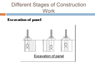
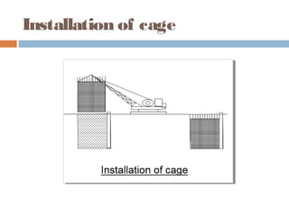
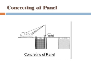
A diaphragm wall is a reinforced concrete wall that is
made in situ constructed in the ground using Under
slurry technique which was developed in Italy in 1948.
 The slurry forms a thick deposit (the cake) on the
walls of the trench which balances the inward
hydraulic forces and prevents water flow into the
trench.
Walls of thickness between 500 and 1500 mm can be
formed in this way.
Commonly used in congested areas.
Can be Installed in close proximity to existing
structure.
Practically suited for deep basements.
Used in conjunction with “Top Down” construction
technique.
Very unstable soil profiles below the water table.
Limited construction time
Where deeper than normal cantilever support may be
required.
Can be Installed to considerable depth.
Formation of walls with substantial thickness.
Easily incorporated into Permanent works.
Designable to carry vertical loads.
Construction time of Basement can be lowered
considerably.
Minimizes settlement of adjacent buildings
Provides strong and watertight wall
No vibration during installation.
High cost
Requires special Equipment
Utility impacts
Step-1: Fixing of Alignment
Step-2: Guide wall Construction
Step-3: Trenching
Step-4: Trench Cleaning
Step-5: Stop ends fixing
Step-6: Reinforcement Cage lowering
Step-7: Placing of Concrete
Step-8: Withdrawal of Stop ends
Guide wall is
Constructed to fix the
alignment of
Diaphragm Wall in the
field
r/f shuttering
curing
r/f
Excavation of panel
Trenching usually carried out under Poly mud slurry.
Poly mud Slurry - Key component.
This Slurry acts as shoring to prevent collapse by
hydraulic pressure and thyrotrophic property.
It is a supporting fluid
Poly Mud's molecular structure allows the polymer to
be completely soluble in water.
Readily available for the primary function of active
chemical bonding and stabilization of soil particles.
Forms jelly under positive pressure into the sides in
case of granular soils.
The Poly Mud suspension gets deposited on the sides
of the hole resulting in the formation of a filter cake in
contact with soil against which the fluid pressure acts.
In case of impervious clay, the Poly Mud does not
penetrate into the soil, but deposits only a thin film on
the surface of the hole.
Parameter Fresh Mix Reused slurry Before Concrete
Pour
Viscosity (seconds) 65-140 65-140 50-140
Density (kg/m3) 1.00-1.04 < 1.08 < 1.04
Sand Content (%) - < 2% < 2%
pH 11-12 11-12 9-12
Joints of adjacent panels to be cleaned to obtain
watertight bond.
Loose materials to be lifted by suitable air lifting
method.
Stop ends to be fixed at the proper position keeping it
truly vertical.
Distance between two Stop ends to be fixed as per
prefixed Panel Layout.
Stop End
Excavation of panel is followed by placing of steel
reinforcement cage in center of the panel.
Face Bar
R/f similar
to column
 Placing of concrete having slump 200/250 mm by
tremmie method.
 Placed by metal hopper with plug at bottom.
 Concrete displaces the slurry.
 The concrete level will be measured at regular
intervals.
Tremie pipe is made up of segments of 1 m in length. The tremie pipe is lifted up
by crane and goes ups and downs to compact the concrete. And this segments
are removed one by one after doing concreting to a certain depth.
Discharging of slurry through pump
Discharging Pipe Pump
After Concreting
 Withdrawal of Stop ends just after the Initial setting of
concrete.
 If retarders are not added, Stop End Pipes shall be
moved up & down not later than 45 minutes from the
time of placing of concrete.
THANK YOU

Diaphragm wall

  • 2.
    A diaphragm wallis a reinforced concrete wall that is made in situ constructed in the ground using Under slurry technique which was developed in Italy in 1948.  The slurry forms a thick deposit (the cake) on the walls of the trench which balances the inward hydraulic forces and prevents water flow into the trench. Walls of thickness between 500 and 1500 mm can be formed in this way.
  • 3.
    Commonly used incongested areas. Can be Installed in close proximity to existing structure. Practically suited for deep basements. Used in conjunction with “Top Down” construction technique.
  • 4.
    Very unstable soilprofiles below the water table. Limited construction time Where deeper than normal cantilever support may be required.
  • 5.
    Can be Installedto considerable depth. Formation of walls with substantial thickness. Easily incorporated into Permanent works. Designable to carry vertical loads. Construction time of Basement can be lowered considerably. Minimizes settlement of adjacent buildings Provides strong and watertight wall No vibration during installation.
  • 6.
    High cost Requires specialEquipment Utility impacts
  • 7.
    Step-1: Fixing ofAlignment Step-2: Guide wall Construction Step-3: Trenching Step-4: Trench Cleaning Step-5: Stop ends fixing Step-6: Reinforcement Cage lowering Step-7: Placing of Concrete Step-8: Withdrawal of Stop ends
  • 8.
    Guide wall is Constructedto fix the alignment of Diaphragm Wall in the field
  • 9.
  • 11.
  • 13.
    Trenching usually carriedout under Poly mud slurry. Poly mud Slurry - Key component. This Slurry acts as shoring to prevent collapse by hydraulic pressure and thyrotrophic property.
  • 14.
    It is asupporting fluid Poly Mud's molecular structure allows the polymer to be completely soluble in water. Readily available for the primary function of active chemical bonding and stabilization of soil particles.
  • 15.
    Forms jelly underpositive pressure into the sides in case of granular soils. The Poly Mud suspension gets deposited on the sides of the hole resulting in the formation of a filter cake in contact with soil against which the fluid pressure acts. In case of impervious clay, the Poly Mud does not penetrate into the soil, but deposits only a thin film on the surface of the hole.
  • 16.
    Parameter Fresh MixReused slurry Before Concrete Pour Viscosity (seconds) 65-140 65-140 50-140 Density (kg/m3) 1.00-1.04 < 1.08 < 1.04 Sand Content (%) - < 2% < 2% pH 11-12 11-12 9-12
  • 17.
    Joints of adjacentpanels to be cleaned to obtain watertight bond. Loose materials to be lifted by suitable air lifting method.
  • 18.
    Stop ends tobe fixed at the proper position keeping it truly vertical. Distance between two Stop ends to be fixed as per prefixed Panel Layout.
  • 19.
  • 20.
    Excavation of panelis followed by placing of steel reinforcement cage in center of the panel.
  • 21.
  • 23.
     Placing ofconcrete having slump 200/250 mm by tremmie method.  Placed by metal hopper with plug at bottom.  Concrete displaces the slurry.  The concrete level will be measured at regular intervals.
  • 25.
    Tremie pipe ismade up of segments of 1 m in length. The tremie pipe is lifted up by crane and goes ups and downs to compact the concrete. And this segments are removed one by one after doing concreting to a certain depth.
  • 26.
    Discharging of slurrythrough pump Discharging Pipe Pump
  • 27.
  • 28.
     Withdrawal ofStop ends just after the Initial setting of concrete.  If retarders are not added, Stop End Pipes shall be moved up & down not later than 45 minutes from the time of placing of concrete.
  • 29.