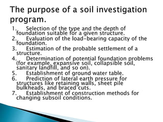
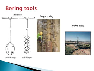
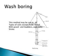
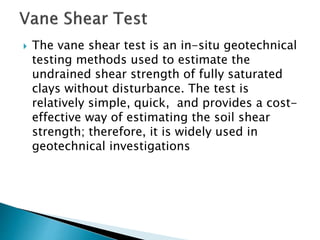
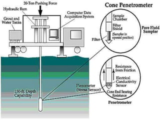
The document discusses site investigation methods for determining soil properties below a construction site. It defines site investigation, explains its purposes such as evaluating load capacity and settlement, and describes exploration program steps from initial information gathering to detailed borings. Common boring types like auger and core borings are outlined. In-situ tests for soil strength measurement are also summarized, including standard penetration, vane shear, plate load, cone penetration, and pressure-meter tests.


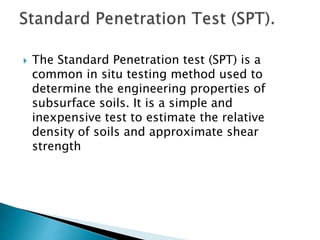


![Geotechnical Engineering-I [Lec #28: Soil Exploration]](https://cdn.slidesharecdn.com/ss_thumbnails/28-180924141716-thumbnail.jpg?width=640&height=640&fit=bounds)


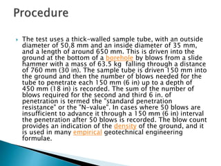
![ANIMAL_CELL_,_TISSUE_AND_ORGAN_CULTURE[1].pptx](https://cdn.slidesharecdn.com/ss_thumbnails/animalcelltissueandorganculture1-260204172026-4462b440-thumbnail.jpg?width=640&height=640&fit=bounds)

