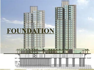
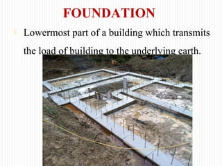
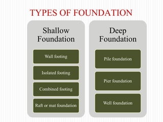
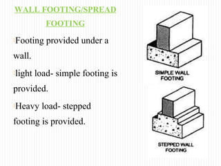
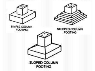
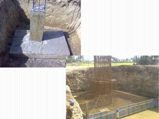
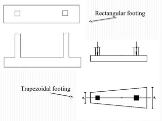
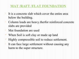
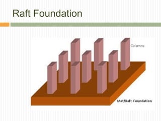
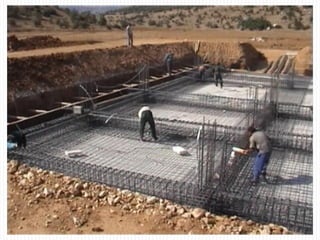
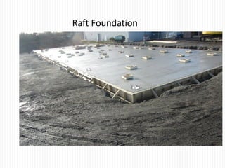
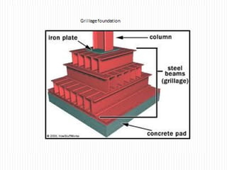
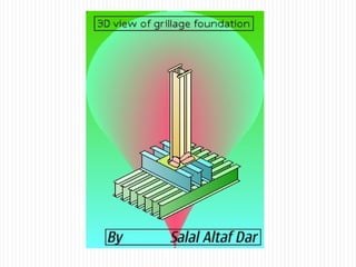
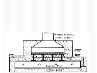
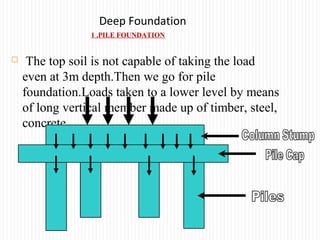
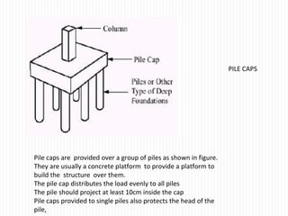
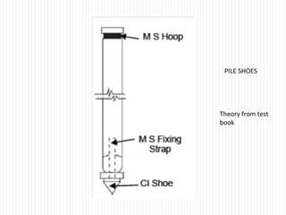
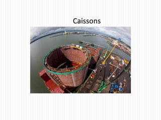
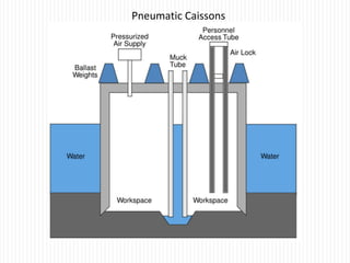
FOUNDATION
FOUNDATION
 Lowermost part of a building which transmits
the load of building to the underlying earth.
Major functions of the foundation
 It distribute non-uniform load of the superstructure
evenly on the subsoil hence it minimize chances of
differential settlement.
 It provides stability against scouring flood water.
 It provides stability against sliding.
 It provides a level surface for the construction of
the superstructure
TYPES OF FOUNDATION
WALL FOOTING/SPREAD
FOOTING
Footing provided under a
wall.
light load- simple footing is
provided.
Heavy load- stepped
footing is provided.
ISOLATED FOOTING/COLUMN FOOTING
It is used to support isolated columns
Size of footing is very large- stepped or sloped
foundation
Reinforced cement concrete footing is provided for
heavy loads.
Load transmitted through the foundation to soil should
be less than bearing capacity of soil.
COMBINED FOOTING
 It is constructed for two or more column
 Isolated footings of individual column overlaps or
when external column is situated near the boundary.
 Footing: Rectangular or trapezoidal.
 Rectangular footing
 provided when load
acting on two
columns are almost
equal.
 Trapezoidal footing
 Provided when load
acting on the column is
very high
 When one of the
column is very close to
the boundary.
Rectangular footing
Trapezoidal footing
MAT /RAFT /FLAT FOUNDATION
 It is a concrete slab which cover the entire area
below the building.
 Column loads are heavy.therfor reinforced concrete
slabs are provided
 Mat foundation are used
 When Soil is soft clay or made up land
 Highly compressible soil to reduce settlement.
 It can face large settlement without causing any
harm to the super structure.
Raft Foundation
Raft Foundation
Foundation for Steel columns- Grillage foundation
High rise Buildings are built with steel columns encased
in concrete. Such columns carry heavy load and hence,
they need special foundation to spread the load over a
large area of soil. Grillage foundation is one such
foundation. It consists of one or more tiers of I section
steel beams as shown in figure. The top tier consists of
fewer but large sized steel beams while the lower tier
consists of large number but smaller sized steel beams.
The column load is transmitted to the top tier through a
base plate. The steel beams are not painted but they are
encased in concrete with a minimum cover of 100mm
beyond the edges
1 .PILE FOUNDATION
 The top soil is not capable of taking the load
even at 3m depth.Then we go for pile
foundation.Loads taken to a lower level by means
of long vertical member made up of timber, steel,
concrete.
Deep Foundation
PILE FOUNDATION
A pile is a slender column made of
wood,concrete or steel. A plie is either
driven into the soil or formed in situ by
cutting a core in the dround and then
filling with concrete.A group of piles are
provided up to the required depth and are
capped with RCC slab.The structure is built
over the pile cap.Piles transfer the load to
the soil by friction or by direct bearing.In
case of direct bearing,the piles are taken
up to the hard strata
Classification of Piles according to method of load
transfer
 Bearing pile
 Friction piles
Bearing piles rest on hard strata and transfer the load by direct bearing.
Such piles are preferred, if hard layer is available at reasonable depth.
Friction Piles transfer the load by friction between the soil and pile. This
type of pile is preferred if hard strata is not available even at considerable
depth. The frictional resistance is assessed before deciding the length of
the pile. The surface of such piles is made rough to increase the skin friction
so as to reduce the required length,
Based on material
 Wooden or Timber pile
 Concrete pile
 Steel piles
 Composite piles
 Sand piles
Concrete piles
 Precast concrete piles
 Cast-in-situ piles
Pre-cast concrete piles
 Are reinforced with steel and
manufactured in factories
 Square section , Circular, and
Octagonal sections with chamfered
corners
 crossectional dimension of piles –
25cm to 60cm
 Length of piles – 3 to 30m
 At lower end, shoes are provided.
 Shoes of 20cm depth and 15cm
width
Advantages
 Piles can driven under water also.
High resistance to biological action of the soil.
Disadvantage
They need more time to manfacture
 They are heavy to handle.
Cast in situ piles
 Cast at the place where they have to function by
driving a casing into an excavated hole
 Filling up the casing with concrete.
 If the hole is filled with plain concrete only, it is
known as Pressure pile.
Cast in situ piles
The load carrying capacity of concrete piles may be
increased by inserting reinforcement caging in the bored
hole and by providing one or two under reams. This is
followed by concreting. Such piles are known as under-
reamed piles. These piles are provided at regular intervals
of 2-3m and then capping beam is provided over them.
Pressure pile & Under – reamed pile
Under –reamed pile
Timber Piles
• Seasoned wooden piles
• Square or circular piles
• Cross-sectional dimension 20 to 40cm
• length 20 times the cross sectional dimension
• Bottom is sharpened and provided with Iron Shoe
• To avoid decay, the top of wooden piles should be below water
table since wooden piles should not be subjected to alternate
wet and dry conditions .Hence, they are preferred for positions
below water table .The portions above water table are built with
concrete.
• Cheap and can be driven Easily
• Load carrying capacity low
• Likely to be damaged while being driven into the soil.
TIMBER PILES
Composite Piles
Composite piles may be timber and concrete or steel and
concrete.
Steel Piles
Tube
I section or H section
Steel Piles
Steel Piles
Box - section
Cross section of steel piles
STEEL PILES :
A steel pile may be rolled steel I-section , or a box
type fabricated section or a tube.
These piles are used as bearing piles .
If tube or box section is used , the soil inside the section is
driven out by compressed air and concrete is filled .
They are commonly used for columns very close to the existing
structures , as they disturb the soil least.
Sand Piles :
These piles are formed by boring a hole of the required
diameter and then filling it with sand .
The sand is rammed until it doesn’t escape or settle.
The top of the sand pile is fitted with concrete to prevent the
movement of sand at the top.
Diameter of sand pile is 30 cm and the length is 12 times the
diameter.
It can take loads up to 1000 kN/m2 or 10000 t/m2
They are economical .
They should not be used in earthquake prone regions.
Pile caps are provided over a group of piles as shown in figure.
They are usually a concrete platform to provide a platform to
build the structure over them.
The pile cap distributes the load evenly to all piles
The pile should project at least 10cm inside the cap
Pile caps provided to single piles also protects the head of the
pile,
PILE CAPS
PILE SHOES
Theory from test
book
Pile Driving and Load test on
piles
Well foundation
Well Foundation
Well foundations are required in areas surrounded by
water, Such foundations are usually required for
foundations of bridge pier,
A cofferdam is a temporary structure built around a
construction site to remove water and make the
construction area reasonably dry.
Caisson is a watertight chamber in which underwater
construction work can be done. After the work is
completed, the caisson becomes a permanent part of
the construction work.
Caissons
Open Caissons
STEINING
Box caisson
Box Caisson
Box Caissons
They are open at top and closed at the bottom.
They are made up of timber, RCC or steel.
They are built on land and then floated to the site and
sunk
Before sinking the box caisson, the bearing surface is
levelled by sand filling
The caisson is sunk by filling with sand or gravel.
The top of the caisson is then plugged.
Pneumatic Caissons

2.foundation

  • 1.
  • 2.
    FOUNDATION  Lowermost partof a building which transmits the load of building to the underlying earth.
  • 3.
    Major functions ofthe foundation  It distribute non-uniform load of the superstructure evenly on the subsoil hence it minimize chances of differential settlement.  It provides stability against scouring flood water.  It provides stability against sliding.  It provides a level surface for the construction of the superstructure
  • 4.
  • 5.
    WALL FOOTING/SPREAD FOOTING Footing providedunder a wall. light load- simple footing is provided. Heavy load- stepped footing is provided.
  • 6.
    ISOLATED FOOTING/COLUMN FOOTING Itis used to support isolated columns Size of footing is very large- stepped or sloped foundation Reinforced cement concrete footing is provided for heavy loads. Load transmitted through the foundation to soil should be less than bearing capacity of soil.
  • 9.
    COMBINED FOOTING  Itis constructed for two or more column  Isolated footings of individual column overlaps or when external column is situated near the boundary.  Footing: Rectangular or trapezoidal.
  • 10.
     Rectangular footing provided when load acting on two columns are almost equal.  Trapezoidal footing  Provided when load acting on the column is very high  When one of the column is very close to the boundary.
  • 11.
  • 12.
    MAT /RAFT /FLATFOUNDATION  It is a concrete slab which cover the entire area below the building.  Column loads are heavy.therfor reinforced concrete slabs are provided  Mat foundation are used  When Soil is soft clay or made up land  Highly compressible soil to reduce settlement.  It can face large settlement without causing any harm to the super structure.
  • 13.
  • 15.
  • 19.
    Foundation for Steelcolumns- Grillage foundation High rise Buildings are built with steel columns encased in concrete. Such columns carry heavy load and hence, they need special foundation to spread the load over a large area of soil. Grillage foundation is one such foundation. It consists of one or more tiers of I section steel beams as shown in figure. The top tier consists of fewer but large sized steel beams while the lower tier consists of large number but smaller sized steel beams. The column load is transmitted to the top tier through a base plate. The steel beams are not painted but they are encased in concrete with a minimum cover of 100mm beyond the edges
  • 20.
    1 .PILE FOUNDATION The top soil is not capable of taking the load even at 3m depth.Then we go for pile foundation.Loads taken to a lower level by means of long vertical member made up of timber, steel, concrete. Deep Foundation
  • 21.
    PILE FOUNDATION A pileis a slender column made of wood,concrete or steel. A plie is either driven into the soil or formed in situ by cutting a core in the dround and then filling with concrete.A group of piles are provided up to the required depth and are capped with RCC slab.The structure is built over the pile cap.Piles transfer the load to the soil by friction or by direct bearing.In case of direct bearing,the piles are taken up to the hard strata
  • 23.
    Classification of Pilesaccording to method of load transfer  Bearing pile  Friction piles Bearing piles rest on hard strata and transfer the load by direct bearing. Such piles are preferred, if hard layer is available at reasonable depth. Friction Piles transfer the load by friction between the soil and pile. This type of pile is preferred if hard strata is not available even at considerable depth. The frictional resistance is assessed before deciding the length of the pile. The surface of such piles is made rough to increase the skin friction so as to reduce the required length,
  • 24.
    Based on material Wooden or Timber pile  Concrete pile  Steel piles  Composite piles  Sand piles
  • 25.
    Concrete piles  Precastconcrete piles  Cast-in-situ piles
  • 26.
    Pre-cast concrete piles Are reinforced with steel and manufactured in factories  Square section , Circular, and Octagonal sections with chamfered corners  crossectional dimension of piles – 25cm to 60cm  Length of piles – 3 to 30m  At lower end, shoes are provided.  Shoes of 20cm depth and 15cm width
  • 27.
    Advantages  Piles candriven under water also. High resistance to biological action of the soil. Disadvantage They need more time to manfacture  They are heavy to handle.
  • 28.
    Cast in situpiles  Cast at the place where they have to function by driving a casing into an excavated hole  Filling up the casing with concrete.  If the hole is filled with plain concrete only, it is known as Pressure pile.
  • 29.
    Cast in situpiles The load carrying capacity of concrete piles may be increased by inserting reinforcement caging in the bored hole and by providing one or two under reams. This is followed by concreting. Such piles are known as under- reamed piles. These piles are provided at regular intervals of 2-3m and then capping beam is provided over them.
  • 30.
    Pressure pile &Under – reamed pile Under –reamed pile
  • 31.
    Timber Piles • Seasonedwooden piles • Square or circular piles • Cross-sectional dimension 20 to 40cm • length 20 times the cross sectional dimension • Bottom is sharpened and provided with Iron Shoe • To avoid decay, the top of wooden piles should be below water table since wooden piles should not be subjected to alternate wet and dry conditions .Hence, they are preferred for positions below water table .The portions above water table are built with concrete. • Cheap and can be driven Easily • Load carrying capacity low • Likely to be damaged while being driven into the soil.
  • 32.
  • 33.
    Composite Piles Composite pilesmay be timber and concrete or steel and concrete.
  • 35.
  • 36.
    I section orH section Steel Piles
  • 37.
  • 38.
    Cross section ofsteel piles
  • 39.
    STEEL PILES : Asteel pile may be rolled steel I-section , or a box type fabricated section or a tube. These piles are used as bearing piles . If tube or box section is used , the soil inside the section is driven out by compressed air and concrete is filled . They are commonly used for columns very close to the existing structures , as they disturb the soil least.
  • 40.
    Sand Piles : Thesepiles are formed by boring a hole of the required diameter and then filling it with sand . The sand is rammed until it doesn’t escape or settle. The top of the sand pile is fitted with concrete to prevent the movement of sand at the top. Diameter of sand pile is 30 cm and the length is 12 times the diameter. It can take loads up to 1000 kN/m2 or 10000 t/m2 They are economical . They should not be used in earthquake prone regions.
  • 41.
    Pile caps areprovided over a group of piles as shown in figure. They are usually a concrete platform to provide a platform to build the structure over them. The pile cap distributes the load evenly to all piles The pile should project at least 10cm inside the cap Pile caps provided to single piles also protects the head of the pile, PILE CAPS
  • 42.
  • 43.
    Pile Driving andLoad test on piles
  • 44.
  • 45.
    Well Foundation Well foundationsare required in areas surrounded by water, Such foundations are usually required for foundations of bridge pier, A cofferdam is a temporary structure built around a construction site to remove water and make the construction area reasonably dry. Caisson is a watertight chamber in which underwater construction work can be done. After the work is completed, the caisson becomes a permanent part of the construction work.
  • 46.
  • 47.
  • 48.
  • 49.
  • 50.
  • 51.
    Box Caissons They areopen at top and closed at the bottom. They are made up of timber, RCC or steel. They are built on land and then floated to the site and sunk Before sinking the box caisson, the bearing surface is levelled by sand filling The caisson is sunk by filling with sand or gravel. The top of the caisson is then plugged.
  • 52.